Chapter 6 — Vessels, heaters, exchangers and storage
The external arrangement must serve what happens inside
Internal collection, phase separation, heat-transfer and removal functions constrain external nozzles, elevations, supports and working space. Reconcile process vessel sketches, selected internals and vendor outlines before fixing the connections. A wrong level can defeat a takeoff, encourage flashing before measurement or obstruct withdrawal. Plant arrangement develops the surrounding space.
The same equipment changes state. A vessel may be empty during installation and filled in service. A reactor may be operating, regenerating or open for catalyst work. A heater may be carrying product or connected to temporary decoking services. An exchanger may be partly disconnected for bundle withdrawal. Preserve those configurations in the fluid, mechanical and access account rather than assume the running arrangement explains every task.
Drums collect, separate and supply
Process drums can provide reflux collection, surge capacity, suction supply or general liquid collection. Horizontal and vertical arrangements place the inventory, vapor space and nozzles differently. Internals such as demisters, baffles, vortex breakers and distribution piping serve particular functions. They are not interchangeable fittings that can be moved to improve external routing without consequence.
A suction drum, for example, may separate liquid from gas before a compressor. The gas outlet and separation internals must deliver the required gas condition, while collected liquid needs observation, drainage and the selected control or protective response. A reflux drum connects condensation, liquid inventory and return to a tower. Its location and elevation affect both the connecting lines and the pump suction arrangement. Rotating equipment develops the inlet conditions of the connected machine, and measurement and control develops the level and flow functions.
Nozzle orientation should reflect the internal job and connected equipment. Locate liquid takeoff and pump-side piping to avoid unnecessary loss and a route that cannot meet suction conditions. Vapor outlets, drains, vents, level connections and manways need their corresponding level, phase and access. Where nozzles connect to internal distributors or baffles, the permitted external orientation is constrained by that internal arrangement. A proposed change should be coordinated with the equipment design rather than made solely from a piping plan.
Vendor-supplied steam drums and boiler-feedwater deaerators bring another package configuration. Steam generation and feedwater deaeration are functions different from ordinary reflux collection. Their selected steam/water, control and access arrangements must be coordinated with the supplied nozzles, internals and supports. A general drum sketch does not establish that package. Preserve the vendor scope and the connected utility requirements rather than independently relocate its functional connections.
Elevation brings several requirements together: liquid head, connected nozzle levels, clearance, maintenance access and common platforms. Horizontal drums often use saddles. Vertical drums may use skirts, legs or lugs according to their selected size and installation. Each arrangement transfers loads differently and leaves different spaces for piping and access. A nozzle inside a skirt or between piers needs room for its flange, insulation and removal task, not only a centerline position.
Drum piping must also accommodate equipment movement and the support of adjoining lines. A convenient shell or platform attachment is not automatically an adequate support point. Establish the actual attachment and reaction basis through analysis and support and restraint decisions. Keep access to internals and manways available while arranging these supports. Opening the equipment or removing connected components creates another load and work state that the running configuration alone does not establish.
Carry the internal drum arrangement into the nozzle and work plan
A horizontal drum example makes these interfaces concrete. The liquid outlet can be fitted with a vortex breaker, while a weir or baffle separates regions inside the vessel. The vortex breaker addresses the outlet flow. It does not make the surrounding liquid a quiet, representative sensing region. Level connections should communicate with the selected quiet region, away from outlet turbulence, and span the operating levels the function must observe. Moving them to shorten an external bridle can change what that assembly represents.
Coordinate the internal feature, actual low/high levels and communicating connections before fixing the outside instrument position.
A pressure connection in the vapor region and a temperature connection immersed in liquid can serve the selected vapor-pressure and liquid-temperature observations. Their phase and location define the information. Another measurement purpose can require another position. A hillside nozzle is a connection placed off the principal vessel axis to obtain a required elevation or access relationship. It can help arrange a level connection or manway, but its projection and opening still need the equipment design and an inspectable outside connection.
Translate the nozzle list into a connected arrangement. Trace the incoming stream, vapor outlet, liquid takeoff, vent, drain, steam-out and instrument paths independently. A steam-out connection and vent at opposite ends can serve a selected cleaning path. Their presence does not establish an isolation or vessel-entry procedure.
Confirm that the selected drain reaches the collecting region. Confirm that a platform or pier does not conceal the flange or valve that must be opened. Then compare the pump suction route with the available-head and flexibility requirements. A shorter connection can reduce loss while transferring more relative movement to the pump.
Support selection changes the realization. A platform carried by vessel trunnions follows a different attachment and movement path from one supported at concrete piers or from grade. Adjoining piping supported from the shell, platform steel or piers likewise sends reactions to different structures. Keep those reactions and relative movements in the equipment/support basis. Leg-supported vessel sketches intended for another service should not be transferred by size alone into a reciprocating-compressor circuit. Cyclic behavior is another selection condition.
Two additions can expose work that a simple drum outline omits. A boot attached below a horizontal vessel has its own lower connections and may require another platform for instrument access. The main drum platform can be perfectly usable while those lower tasks remain unreachable. A mixer requires an upward withdrawal path for its selected shaft and assembly. A removable floor section above it can preserve that path in a structure, provided its handling and reinstatement are defined. Neither the boot's small size nor the mixer's compact motor describes the complete work envelope.
For a sloping drum, declare its work point and slope, retain a horizontal platform, and specify whether nozzles and saddles remain vertical or follow another selected orientation.
Rotating a vessel outline does not automatically rotate every nozzle or support detail. If a nozzle is inclined to the required pipe run, calculate the resulting offset and connection geometry from the selected outline. This is a dimensional interface, separate from choosing the drum elevation for suction head or access.
Tower internals govern nozzle and access choices
Tray/downcomer and packed-bed/distributor arrangements determine where feeds, reflux and draw-offs act and where personnel and parts can enter.
A downcomer is not merely a vertical obstruction. It routes liquid and contributes to the tray's liquid level and vapor-seal arrangement. Single-pass and multiple-pass trays occupy different internal regions, affecting manway orientation and the space available to enter and work. Bubble-cap, sieve and other tray configurations have their selected flow and support arrangements. Their exact dimensions come from the process and internals design. A historical tray table does not establish the dimensions of a new tower.
Packed beds need their selected supports and liquid distribution. A feed nozzle clear of external piping can still be poorly located relative to the distributor. Internal piping can extend the available nozzle orientation but adds parts, supports and maintenance. The purpose of the arrangement is useful distribution and access, not unrestricted freedom to put every nozzle on the easiest side.
Reflux is introduced at the selected upper location to distribute liquid over the contacting region. A baffle or internal distributor can be needed according to the inlet and tray arrangement. Side feeds and liquid draw-offs likewise have internal relationships. Reorienting a nozzle to shorten external piping can alter that distribution or create an internal pipe that is more costly to install, inspect and replace. Coordinate the alternative with the equipment and internals design, preserving the function before comparing the external route.
Temperature can vary along a tower. A bottom section and an upper section need not grow by the same rate when brought from installation to operation. Determine movement to each connected nozzle from the fixed or supported reference. Use the applicable temperature profile and material behavior, not one uniform temperature for the complete vessel. A nozzle near the top can accumulate movement from several lower sections.
Thermal and mechanical analysis develops the quantitative evaluation. This chapter establishes why the equipment profile and reference are required inputs.
Pump suction, access, low clearances, a reboiler and common platforms can impose different tower-elevation demands. If these are independent lower bounds on the same tangent-line point and datum, their maximum governs the least feasible elevation. Additional upper limits or coupled variables require a combined layout comparison. Changing a platform, pump or reboiler can change the bounds themselves.
A skirt-supported tower also needs skirt access, nozzle space and the correct foundation/support interfaces. Platforms and ladders should serve the selected operating and maintenance tasks. Tall-vessel guides, pipe supports and attachments must carry their evaluated loads while permitting intended relative movement. Keep manways, trays, packing removal and lifting paths available. The tower's external outline does not show all of the work its internals require.
Locate the entry between the internals that occupy it
A tower manway needs a usable route into the vessel at its actual elevation. A nozzle clear of outside piping can still open directly against a downcomer hanging from the tray above. Read the tray arrangement in plan and section together. The plan identifies occupied circumferential regions. The section distinguishes the downcomer descending into the entry space from one beginning below its floor.
In the single-pass comparison, liquid traverses a tray toward an edge downcomer, then arrives at the next tray from the opposite edge. Successive downcomers oppose one another. In the two-pass comparison, center and side downcomers alternate. One level divides liquid from a center region toward two side regions. The next collects from both side regions toward the center.
These are different internal flow configurations, with different entry constraints. Their selected tray support, liquid-retention and vapor-contact construction remains part of the internals design.
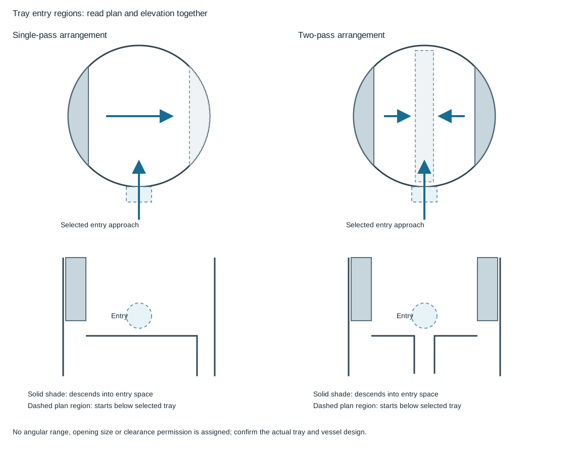
Figure 6.1. The sections identify the downcomers descending from above and the passages beginning below the selected tray. The two-pass entry is shown at the level with side downcomers descending from above, leaving an approach between them. An incoming center downcomer at the alternate level would obstruct that central approach. Shading identifies physical regions rather than a universal allowed manway angle. Structured tray regions and entry constraints.
For the illustrated two-pass construction, the useful entry levels are separated by an intervening tray because the incoming center downcomer obstructs the alternate level. The position between side downcomers still needs confirmation against the actual opening, tray supports and internal piping. In a single-pass arrangement, a wider circumferential choice can remain between the edge downcomer regions. This does not make every elevation or outside approach usable. Carry the intended personnel and component-removal paths through the complete shell opening.
Choose the manway level and platform together with the vessel and internals design. Moving an opening by one tray can change platform and ladder economy, while also changing the internals reached from that opening. The outside route from the tower maintenance side and cover handling belong to the same access task. So does passage of tray sections or other removable parts. Reconcile those tasks with equipment spacing and access. Retain the actual opening and internals dimensions rather than adopt a generic clearance from a plan sketch.
Preserve the delivery region when changing the external nozzle
Feed, reflux and draw-off connections have different internal duties. Reflux enters the selected upper contacting region and must be distributed over its tray. A feed can require delivery to a specified region or distributor on its own feed tray. A reboiler draw-off instead communicates with the selected liquid collection or sump region. Their common description as “process nozzles” does not make their internal endpoints interchangeable.
The selected single-pass reflux example below holds the internal delivery point fixed while comparing two external entry candidates. Candidate A enters near that point and turns down to the tray. Candidate B enters elsewhere on the shell and uses a longer internal route to reach the same delivery point. The outlet-side downcomer stays in its selected region in both comparisons. The candidates are alternatives for review. Drawing the internal pipe does not establish its capacity, support or acceptability.
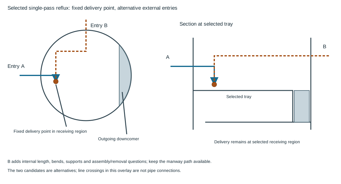
Figure 6.2. The plan compares external entry A and candidate B against the same marked delivery point and downcomer region. The section locates the internal route above the tray and its delivery at the selected receiving region. The selected path needs its own elevation, supports, clearance and assembly/removal basis. Schematic line crossings do not imply connections. Structured endpoints and candidate routes.
Internal bends and distributing pipes can extend the external orientation choices. They also introduce length, fittings, supports and joint or removal interfaces inside the tower. Keep the pipe out of the manway entry path and evaluate its relationship to tray sections and internal access openings. An internal flange can be proposed to permit tray removal or release a pipe that otherwise interferes with a tray manway. In that case, the reason and selected removable construction must remain explicit. An internal flange is not required merely because another vessel example has one.
The internal pipe also occupies process space. Liquid and foam above a tray can meet a horizontal pipe as an obstruction to their intended movement. A baffle or distributor can be needed to handle the selected inlet velocity and distribution duty. Those requirements must be evaluated with the tray and vessel design before a preferred external route is fixed. The least expensive outside nozzle location can add a more costly or less maintainable internal assembly.
Two-pass feed alternatives require their own consistent delivery arrangement. Two external nozzles can supply two internal receiving regions. A single external nozzle can instead supply a distributing arrangement serving both. The second choice does not simply reduce the nozzle count while leaving everything else unchanged. Its internal branches, elevations, support and removal paths have to be defined.
Preserve the center and side downcomer relationships for that chosen tray set. Do not transplant the single-pass reflux route into it without a new internals evaluation.
For a reboiler or side draw-off, identify the collecting region, liquid seal and takeoff endpoint independently. A nozzle communicating with a sump or downcomer collection has another function from a feed nozzle discharging over a contacting tray. The required elevation and internal outlet path follow that collection arrangement. Keep connection duty, internal delivery/collection point, tray level, external orientation and removable parts together at the vessel interface.
A changed nozzle or tray arrangement reopens those connected decisions.
Reactors need process connections and a catalyst-work path
A reactor's bed, screens, inlet distribution, outlet collection and selected catalyst or inert materials constrain its flow path. Desulfurization, hydrotreating and related services can require different operating and regeneration connections.
The reactor may have fewer principal process connections than a fractionation tower, but their placement remains consequential. In the described vertical arrangements, process inlet and catalyst-loading access are associated with the top region. The outlet and unloading connection serve the lower region. A skirt, lug or ring-girder support changes how the outlet and unloading nozzle can clear the supporting structure. The selected reactor can use another arrangement. Use its actual process and vessel information rather than copy a typical nozzle orientation.
High-pressure shell thickness can alter external flange and clearance geometry. Insulation, nozzle projections and internal connections also affect the useful envelope. Confirm the selected construction before fixing nearby piping or a working platform. A nominal shell diameter is not necessarily the complete outside dimension around a nozzle or access cover.
Temperature and sample connections need positions that serve the process measurement while allowing operation and maintenance. These functions should be coordinated with piping and platforms, not left to an instrument detail after the reactor area is full. Instrumentation develops the sensing purpose and installation conditions, while branches and connections develops the physical connection mechanics.
Several internal levels need not mean several shell openings
The mechanical arrangement of reactor temperature connections can use separate side-shell penetrations or a selected assembly entering from the top. These choices place the pressure-boundary openings and removable parts differently. Several points at different catalyst-bed elevations remain separate physical locations even when they share one entry assembly.
In the side-entry comparison, each selected connection carries an individual inserted component to its internal position. Its outside withdrawal corridor follows the component's insertion axis, which can be inclined. Adjacent piping, platforms and steel must leave room for the full removable part and its handling task. In the top-entry comparison, one long assembly extends down through a selected top opening to several internal elevations. Its release and extraction are primarily overhead, requiring the specified long withdrawal path above that opening.
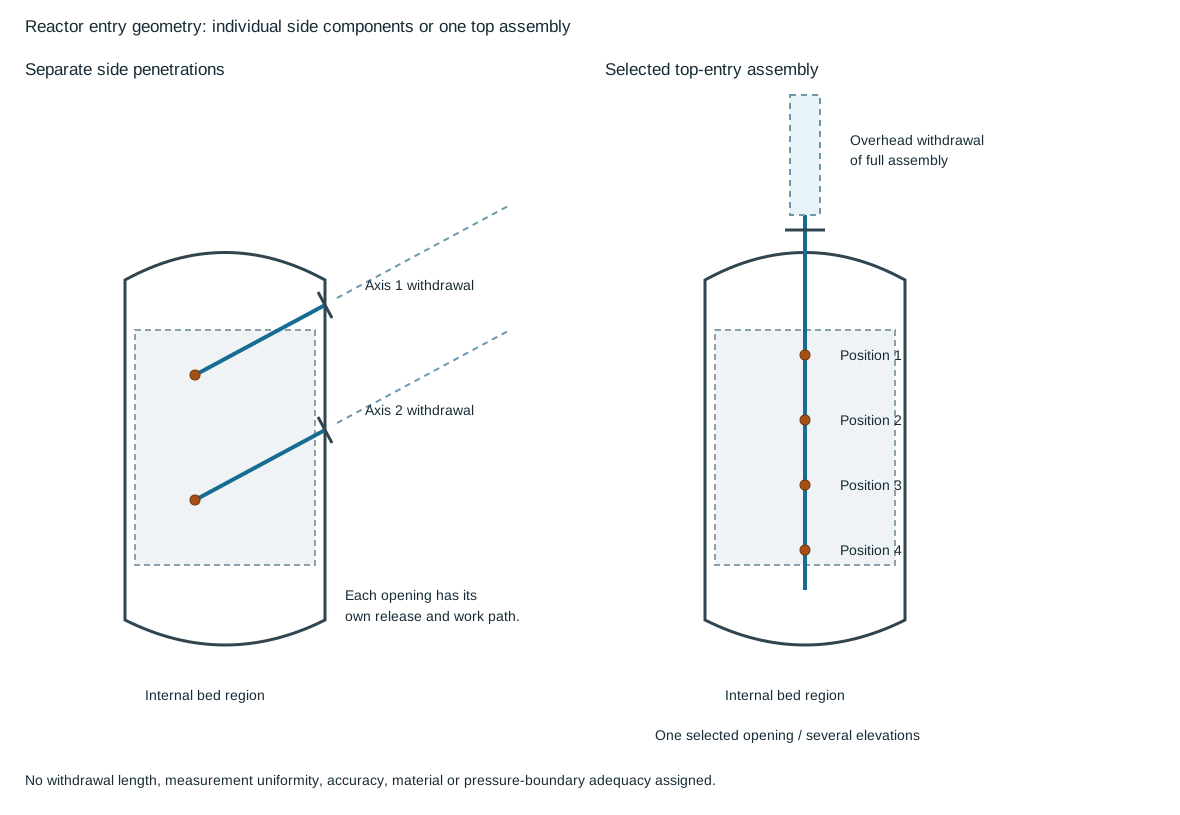
Figure 6.3. The side-entry and top-entry outlines are independent alternatives. Point marks identify distinct internal elevations only. Dashed corridors follow the removable assemblies. They have no assigned lengths or minimum clearances. The top-entry example uses one selected opening for several internal positions. Structured penetrations, internal positions and withdrawal paths.
| Mechanical choice |
Internal and external relationships to retain |
| Separate side-shell connections |
Each shell opening, inserted component, internal position and withdrawal axis; local release and handling space at each elevation |
| Top-entry assembly |
Selected top nozzle or maintenance-access entry, internal assembly fit and positions, overhead release and full assembly withdrawal path |
Top entry can reduce the number of shell penetrations associated with the represented positions while increasing the length and overhead demands of the removable assembly. A side-entry arrangement distributes those tasks over the vessel elevations. Compare those consequences against shell thickness, insulation, actual nozzles, internal bed/support geometry, platform access and available lifting space. The assembly can enter through a maintenance access rather than a separate nozzle. Then its relationship to catalyst loading and opening that access must be resolved with the selected construction.
The mechanical comparison does not establish equally representative positions or uniform vessel temperature. Nor does it establish acceptable vibration or strength for a long assembly. The selected component materials and pressure-boundary design remain required interfaces. Keep this geometry with the temperature connection basis and actual equipment supplier information. Then reserve the verified removal envelope in the piping and platform arrangement.
Catalyst handling introduces a work path through the equipment. Top access, unloading routes, lifting or transport, temporary facilities and internal removal space belong in the arrangement. A loading connection integral with an inlet or manway can require that connection to be dismantled before work proceeds. Identify the remaining piping/support state and the place for removed items. The source-supported layout account does not establish a universal catalyst-loading or vessel-entry procedure. Those activities require the selected service, isolation, cleaning and work basis.
Regeneration and other special states can impose different temperatures, flow paths and internal or external conditions from normal production. Preserve the relevant interfaces when evaluating piping movement and access. The same principle applies to replacement of catalyst or internals: a change that affects distribution, pressure loss or temperature can reopen external piping assumptions. Readiness, operating integrity and intervention carry the work into the applicable verification and return-to-service route.
Heat exchangers contain two different flow arrangements
Keep each exchanger side's service, phase, pressure and temperature with its actual flow region and maintenance arrangement.
In a shell-and-tube exchanger, one fluid passes through tubes while another passes around their outside within the shell. Channel partitions can make several tube-side passes. Baffles direct shell-side flow and support the bundle. Pass configuration affects nozzle positions, pressure loss and the physical removal arrangement. A fixed-tubesheet construction, a removable bundle and a U-tube arrangement offer different access to the surfaces and components. The selected configuration determines what can be cleaned or withdrawn.
A TEMA configuration designation can identify the front-end, shell and rear-end arrangements before a detailed outline is available. It is useful for interpreting the equipment and its likely access needs. It does not establish a heat-transfer duty or current compliance. Use the adopted design basis and selected vendor configuration. Do not treat a historical service-class association as a universal selection rule.
Trace the two sides before assigning a nozzle
A shell-and-tube section should be read as two separate contained flow paths. Follow each connection to the region it actually opens into. A channel nozzle opens into a tube-side compartment. A shell nozzle opens into the space around the tubes. The tubesheet and tube walls separate those regions. Their proximity in an outside view does not make the connections interchangeable.
Record the service, phase, pressure, temperature and material basis against the correct side before arranging the external piping.
In the two-tube-pass, one-shell-pass example below, the channel pass partition separates the inlet compartment from the outlet compartment. Fluid entering the upper compartment travels through one group of tubes and turns within the rear floating-head cover. It returns through the other group to the lower compartment. The partition prevents a direct inlet-to-outlet shortcut in the channel. The rear return space belongs to the tube side even though it lies within the outer shell-cover envelope.
A U-tube bundle provides another return arrangement: the tube bends themselves join the outward and return legs, and only one tubesheet is needed. These constructions perform a related flow operation with different parts and access tasks.

Figure 6.4. The colored arrows explain the illustrated paths. Tube-side reversal occurs at the rear head. Shell-side flow crosses the outside of the tubes through successive baffle windows. The section is schematic and has no dimensional scale. Structured paths and components.
The shell-side stream enters near one end and crosses the tube bundle through openings left by successive transverse baffles. It leaves near the other end. These cross-bundle turns still form one shell pass. A longitudinal baffle instead divides the shell along its length and can establish a two-pass shell route. A channel pass partition, a transverse shell baffle and a longitudinal shell baffle therefore need distinct names in a nozzle review. Their functions cannot be inferred simply by counting lines or arrows in a section.
The section also distinguishes the stationary tubesheet, floating tubesheet, floating-head cover and outer shell cover. Removing the channel cover gives a different access opening from removing the outer shell cover. Releasing a floating head is another operation again. Supports carry the shell, while the internal construction governs the bundle's movement and removal. Use this part-by-part account with the withdrawal method, rather than treating every end closure as a single interchangeable “head.”
Read a configuration designation in three parts
Read a TEMA designation as front head, shell and rear-head/bundle-return construction, in that order.
It identifies physical arrangements that help frame piping and maintenance questions. Its historical set contains four front-head, six shell and seven rear-head entries. The adopted current standard and vendor design establish the applicable designation for a project.
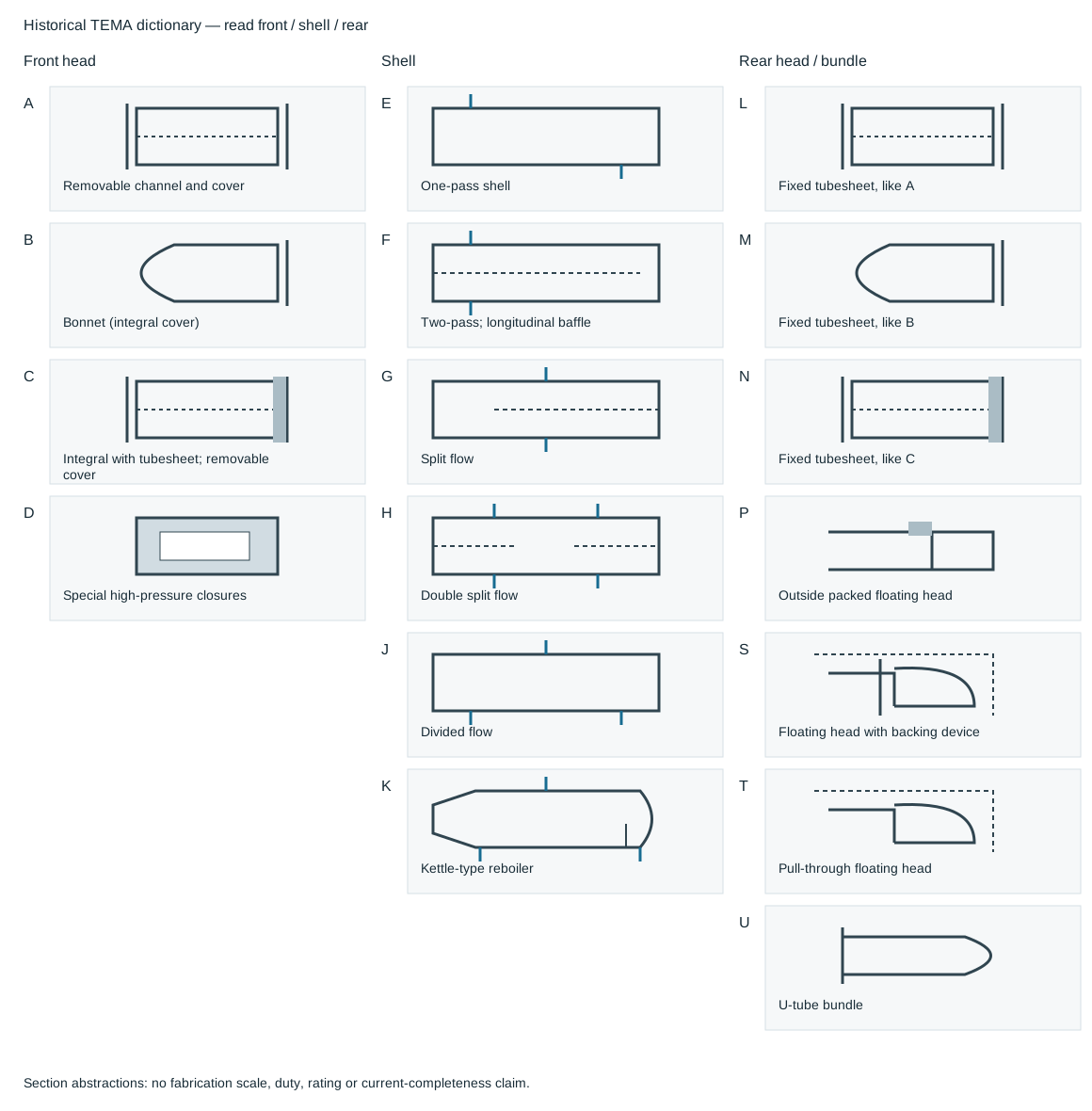
Figure 6.5. Front-head, shell and rear-head alternatives are separate choices. The small sectional sketches emphasize the distinguishing construction, not fabrication dimensions or a complete assembled exchanger. Selectable letter records.
| Position |
Letter |
Construction meaning |
| Front head |
A |
Removable channel and cover |
| Front head |
B |
Bonnet with integral cover |
| Front head |
C |
Integral with tubesheet, removable cover |
| Front head |
D |
Special high-pressure closures |
| Shell |
E |
One-pass shell |
| Shell |
F |
Two-pass shell with longitudinal baffle |
| Shell |
G |
Split flow |
| Shell |
H |
Double split flow |
| Shell |
J |
Divided flow |
| Shell |
K |
Kettle-type reboiler |
| Rear head |
L |
Fixed tubesheet, like A stationary head |
| Rear head |
M |
Fixed tubesheet, like B stationary head |
| Rear head |
N |
Fixed tubesheet, like C stationary head |
| Rear head |
P |
Outside packed floating head |
| Rear head |
S |
Floating head with backing device |
| Rear head |
T |
Pull-through floating head |
| Rear head |
U |
U-tube bundle |
Use the selected construction to establish cover/body release, connected-piping removal, shell-side cleaning and bundle withdrawal. The designation supplies neither pressure rating nor a certified removal sequence. A removable cover does not establish that the bundle can be pulled through that end.
AES decodes as an A removable channel and cover, E one-pass shell and S floating head with backing device. Its sectional example has a channel partition, stationary tubesheet, transverse baffles, floating tubesheet, floating-head cover and split ring inside the outer shell-cover arrangement. Front-cover access, rear-shell-cover access and release of the floating-head backing parts are different tasks. Identify their sequence and handling envelopes on the selected supplier information before arranging piping across either end.
AKU decodes as the same A front head, a K kettle shell and a U-tube bundle. Its illustrated tube-side return is formed by the U bends. It is not the AES floating-head assembly transplanted into a larger shell. The kettle section includes an enlarged shell region and a weir beyond the bundle. Those internal liquid and vapor regions have consequences for shell connections, as developed in the kettle region account.
The designation does not give the operating liquid level, duty, material, design pressure or nozzle schedule. Check those items against the selected equipment and process basis.
Compare nozzle alternatives within the same internal arrangement
The nozzle patterns below show why changing an external connection begins with the internal flow regions. The one-pass shell examples place shell nozzles at different ends of the bundle region. The two-pass shell examples place them near the same end on opposite sides of the longitudinal division. Split-flow and double-split-flow sections introduce different divisions and connection patterns.
The repeated one-pass patterns (alternatives 1 and 5) and two-pass patterns (alternatives 2 and 6) retain the same nozzle geometry. Their rear shell closures differ. Alternatives 1 and 2 show a flanged rear closure. Alternatives 5 and 6 show an unflanged closure.
The nozzle pattern alone therefore does not establish rear-cover access. A kettle shell and a shell with a far-end tube-side connection add further alternatives. These are configuration examples, each read on its own. Their features must not be combined into an unexamined new arrangement.

Figure 6.6. Eight section patterns retain the distinct source alternatives. They include the flanged rear closures of alternatives 1 and 2 and unflanged rear closures of alternatives 5 and 6. Blue ports belong to the shell. Orange ports belong to the tube-side end compartments. Port marks show connection locations, not service direction, nozzle size, angular orientation or engineering permission. Structured alternatives.
A proposed relocation must preserve the connection's side and intended region, the pass division and return path, and the required phase behavior. Review the changed arrangement with the exchanger design, then update the nozzle schedule and outline together. Moving a shell connection across a longitudinal division or putting a tube-side connection into another channel compartment can change the route through the equipment. A shorter external pipe does not establish equivalent internal behavior.
Retain nozzle facing/projection, foundation/saddle clearance, cover/bolt access, bundle handling/insulation, equipment movement and attachment loads.
The drawings provide no nozzle dimensions, thermal duty or pressure-loss curves. Their useful result is construction questions and distinct alternatives to take to the equipment interface. The actual material, pressure, temperature and operating-state requirements carry forward into the vendor-outline review.
A double-pipe or hairpin arrangement puts one flow path inside another. Fins can increase the heat-transfer surface, and modules can be connected in arrangements suited to the duty and pressure service. The small-diameter form can be useful where a large shell is unattractive, but the connection and withdrawal geometry still matter. A hairpin must have its specified removal path. Shortening external piping across that path can defeat the modular maintenance advantage.
Plate exchangers direct hot and cold fluids through alternating channels in a plate pack. The plate and gasket pattern forms the distribution and pressure boundary, while the carrying bars, covers and compression arrangement hold the pack. Access can involve releasing and opening the pack rather than withdrawing a long tube bundle. Gasket/material and operating limits remain those of the selected construction. The compact form alone does not establish suitability for a pressure, temperature or fluid.
A spiral exchanger forms continuous passages from a wrapped plate arrangement, with its selected covers and nozzles. Its access and support differ from a shell-and-tube unit. Compare those differences against the service, cleaning and maintenance task. Do not select every exchanger on surface area or plot-space savings alone. Compact equipment can save space without eliminating the need to reach and service its actual internal parts.
The vendor outline is a functional interface
Nozzle side, orientation, elevation, facing and projection influence the external route. They also remain constrained by internal flow, construction and maintenance. A proposed nozzle change can reduce an unnecessary loop or improve a stacked arrangement, but it should be reviewed with the equipment design. The piping layout does not have independent authority to move an internal flow connection.
Locate related exchangers to serve the process and the required removal path. A channel cover, shell cover, bundle or hairpin can need a different withdrawal direction and lifting position. Fixed handling devices, trolley or crane arrangements and mobile extractors are alternatives whose usefulness depends on the actual equipment and job. A route clear of the running equipment can obstruct a cover or bundle as soon as it is moved.
Removal dimensions must be established for the selected equipment. An uncertain catalog dimension or incomplete preliminary outline should remain an unresolved interface until clarified, while alternative layouts can be studied around a declared envelope. Do not infer a missing dimension from the neighboring catalog row or assume a larger-looking drawing provides a certified clearance.
Exchanger supports and thermal behavior also matter. The selected equipment can need movement between its support points and coordinated freedom in the attached piping. Stacked units can simplify a process connection but add support, nozzle and maintenance demands. Include equipment displacement and attachment reactions in analysis and support design, and preserve the physical clearances through installation.
Pressure, material and connection differences across equipment and field piping need their actual design basis. A nozzle rating is not an external-load allowable. A matching flange size is not proof that the bore transition, material or inspection requirement is satisfied. Materials, joints, pressure design and fabrication quality develop those requirements. This chapter keeps them connected to the actual flow side and equipment configuration.
Select the withdrawal method before reserving the corridor
The channel, bonnet, shell cover and bundle are different removable parts. For a horizontal exchanger, locate the bundle end toward the selected maintenance approach and retain bonnet or cover handling on its own side. An operating line that fits beside the shell can still block a flange bolt, davit sweep or bundle as it leaves the equipment. Paired and grouped arrangements should therefore be checked at the channel/flange envelope as well as the shell section. Controls can occupy useful side space when their work position and removal path remain clear. Compact pairing does not make that side space unlimited.
The selected pulling and carrying equipment determines how much of the outside corridor is used. One pulling-post arrangement locates its post at twice the bundle length from the illustrated exchanger end. A trolley-beam arrangement instead reserves a travel dimension of bundle length plus a nominal 2 ft, paired with 610 mm, in its illustrated structure. These are different geometries and methods, not two interchangeable rules for the same free space. Identify the dimension's endpoints, the bundle length and the equipment travel before using either as a planning basis. The actual supplier, rigging and handling arrangement establishes the final envelope.
Table 6.1. Different internal-access tasks create different outside paths.
| Selected form and method |
Consequential path or interface |
| Horizontal removable bundle with fixed pulling and carrying equipment |
Axial extraction, supporting/holding positions, trolley or gantry travel, then lowering and transfer |
| Horizontal bundle with a mobile extractor and crane |
Extractor approach and shell-flange clamp, reaction path, crane balance and lift, then grade/vehicle transfer |
| Vertical removable bundle |
Upward extraction and overhead lift; lower cover handling can be another task |
| Spiral exchanger |
Cover-plate swing plus any intentionally removable connected spool |
| Plate exchanger |
Opening the pack and withdrawing individual plates within the selected carrying-bar arrangement |
| Air cooler requiring major section removal |
Crane approach and section lift, with header, motor and minor-servicing access retained separately |
A hydraulic extractor offers a useful load-path example. It clamps at the exchanger shell flange. Its hydraulic pulling system acts against the selected reaction arrangement while the crane and leveling system carry and balance the extractor and withdrawn bundle. The load and center of gravity change as extraction proceeds. A crane that can reach the initial position and a clear axial corridor answer only parts of the task.
Equipment weight, pulling reactions, flange/structure capacity, holding arrangement and final transfer must be evaluated together. A catalog or historical description of one extractor's weight or force is not the rating of the tool brought to the site.
A fixed trolley or traveling gantry adds permanent steel, rails, pulling points and maintenance. Mobile handling can avoid some permanent structure while requiring a useful approach, setup and lift path for the actual machine. Compare the selected work frequency, part size/weight, operating neighbors and access before assigning an economic preference. Stab-in reboiler withdrawal can require a removable handrail section at its outward path. Define the temporary protection and reinstatement rather than assume that missing railing is a complete access solution.
Nozzle alternatives should be studied with this withdrawal plan. A changed shell nozzle can simplify an external route, while the pass construction limits where it can act. A gooseneck or elbow nozzle can reduce spacing between stacked exchangers by turning the connection within a shorter vertical envelope. It changes the equipment connection and must be accepted with its internal flow, fabrication and load basis. For an air-cooled condenser, a single-pass far-end outlet and a double-pass same-end outlet can produce very different gravity-return lengths and elevations. Reorienting the cooler or changing its passes can simplify the external path, but those alternatives also change the thermal and equipment configuration.
Material and movement can reverse a visually compact choice. Avoid making a large alloy route acquire an unnecessary offset solely to accommodate a smaller carbon-steel line when moving the smaller connection provides a workable alternative. A loop between hot feed exchangers and a selected moving support at one exchanger are distinct ways of accommodating a defined relative movement. The moving support changes equipment reactions and alignment as well as pipe geometry. It is not a generic substitute for flexibility. Evaluate the actual supported equipment, displacement and terminal limits through analysis and supports.
The supplied release joint determines what must move
A hairpin's external connection and its internal withdrawal route need separate inspection. In one supplied arrangement, a compression/disconnect assembly allows tube release and withdrawal from the return-housing end. The connected field manifolding remains in place. The shell and tube connections, seal rings, split rings, compression flanges, end covers and tube-return connector are parts of that particular release arrangement. A conventional sketch that assumes every external flange must be disconnected can introduce unnecessary breakout joints while still leaving the real withdrawal end obstructed.
Use the selected assembly drawing to identify pressure-boundary parts, the release joint and withdrawal end.
Trace the released part through its complete axial travel, supporting and lifting positions, and final transfer. Check the tooling and hand access at the release parts as well as the long extraction space. The release mechanism can reduce dismantling of field piping. It does not remove isolation, draining, support, handling or reassembly work. Do not infer the release sequence or reusable seal condition from the name hairpin.
Compare two installation candidates using that actual mechanism. A manifold retained at the connection end can simplify intervention if the supplied release design permits it. A removable field spool can instead provide access where the selected unit or neighboring arrangement requires it. Additional flanges introduce pressure-boundary joints and maintenance work, while fewer flanges can make an otherwise necessary intervention impractical.
Decide from the actual release and handling path, connection integrity and service conditions. The equipment procedure establishes the permissible disassembly and reassembly actions. The layout preserves the space and load path needed to perform them.
A maintenance connection can carry a different load path
Consider a particular tower-supported vertical reboiler arrangement that does not require springs. Its selected detail leaves the reboiler lug above platform support steel in the initial connected configuration. Before the supporting connection is opened for channel and bundle work, a shim engages the platform load path. The platform then carries the remaining reboiler during the specified maintenance state. Unbolting the nozzle and channel connection before establishing that path would change what holds the assembly.
Figure 6.7 isolates the relationship. The illustrated detail uses a nominal 1-in gap, paired with 25 mm. That is the particular example dimension, not a clearance to adopt for other equipment. Adding the shim changes contact and reaction, so it changes the mechanical system even while the equipment remains at almost the same drawn position. The selected platform, lug and supporting structure must be able to carry the relevant load and preserve stability before the connection is separated.
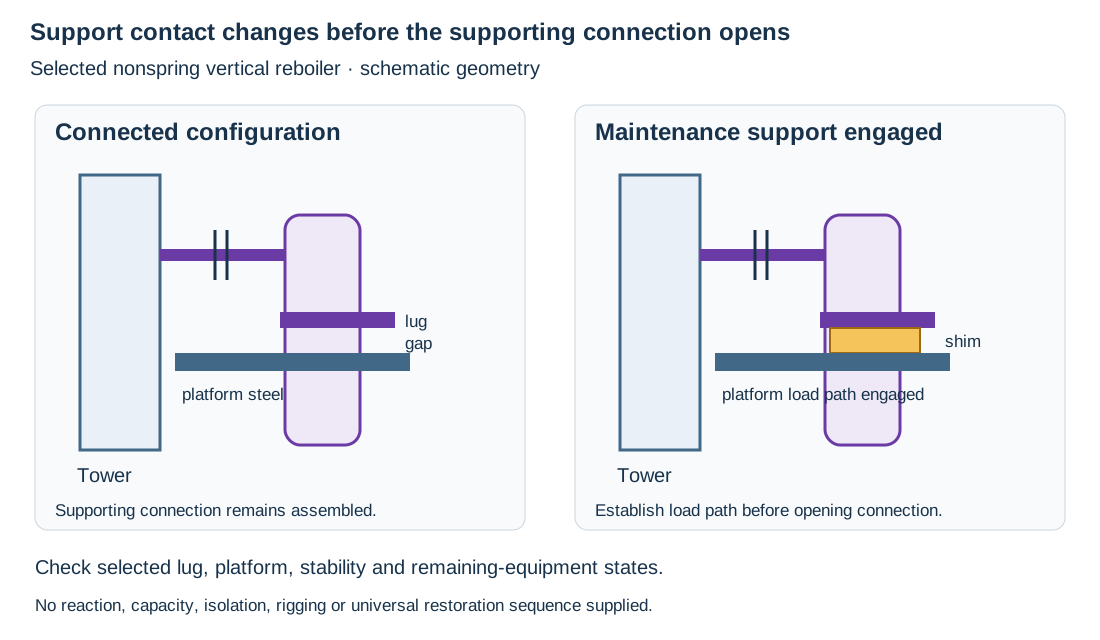
Figure 6.7. A bounded nonspring tower-supported reboiler example. A gap separates the lug from platform steel in the connected configuration. A shim engages that support before the supporting connection is opened. No reaction magnitude, structural capacity or execution approval is supplied. Structured states.
A spring-supported reboiler and an independently supported vertical exchanger have different operating and maintenance premises. Do not transfer the shim detail merely because the vessels are vertical. Follow the actual connection and support arrangement. Include what remains after channel removal and what the lifting system carries during bundle extraction. The removal drawing needs those states as well as the free space above and below.
Return to service requires the intended operating configuration to be restored under the selected work basis. This example explains a maintenance load handoff. It supplies no universal shim-removal or spring-setting sequence. Verify the actual support contacts, connection restoration and movement freedom specified for the installation. A retained temporary support can alter operating loads even if the pressure boundary has been successfully reassembled.
A horizontal exchanger transfers connected-pipe effects through its nozzles and shell to the supporting footings. A historical preliminary footing screen makes one part of that account explicit. Under that adopted method, thrust exceeding 30% of the exchanger weight carried by the particular footing triggers detailed stress analysis. Let be total exchanger weight as a force, and let and be the fractions carried by the channel and shell footings. The screen values are
Fractions are dimensionless. Screen thrust and weight use the same force unit. The method's normal-distribution assumption is and , giving and .
These are checked proportions under a stated preliminary basis, not verified footing loads or equipment acceptance limits. The actual distribution, thrust direction, relevant state and load combinations must agree with the adopted comparison.
The coefficient 0.30 is not an actual contact-friction coefficient. A sliding footing's contact material, normal reaction and restraint determine its frictional behavior. A nozzle force-and-moment or material-stress check is another evaluation again. Passing a footing screen does not establish nozzle acceptability. A low-friction slide detail may reduce particular transferred forces but needs its own contact, movement and foundation evaluation. It does not guarantee a remedy or reconcile an incompatible analysis assumption by choosing the apparently stricter number.
Structured screen method preserves the quantities and scope.
Reboiling and condensation make head and phase central
A reboiler supplies heat that produces vapor for the connected process. A condenser removes heat and changes the returning phase. Their elevation and piping influence circulation and phase handling, so the connection cannot be developed solely from the shortest plan route.
A thermosiphon arrangement relies on a density difference to provide circulating head. The difference is between column liquid and the vapor-liquid mixture in the reboiler path. Piping resistance consumes part of that available head. Keep the loop's geometry, liquid levels, mixture conditions and pressure losses associated with the selected reboiler and operating state. Adding an elevation, long route or restrictive component can change circulation even if the heat-transfer equipment itself is unchanged.
Horizontal and vertical arrangements put the flow paths and supports differently. A horizontal thermosiphon unit can be located near grade with a short connection to the column. In the described vertical arrangement, liquid enters below and a vapor-containing stream leaves above. The unit can be supported from the tower or from a separate structure according to the selected equipment. The tower's ability to carry the reboiler and its attachment reactions must be established. A convenient lug location or nearby platform is not proof of capacity.
A kettle arrangement contains a boiling region with its selected level and withdrawal arrangement. Its relationship to the tower liquid level differs from a simple external once-through route. A pump-through or fired reboiling arrangement adds another source of flow/head and equipment interfaces. Use the selected process configuration to decide which elevation and circulation constraints apply. The name reboiler does not define them all.
A bounded historical screening method for vertical thermosiphon connections relates inside diameter to duty:
with diameter in inches and duty in MMBtu/h. These numerical ranges have that unit convention. They are not dimensionless physical constants.
This screen is not a selected nominal pipe size, a hydraulic calculation or a complete design result. It supplies neither fluid-property validity bounds nor a demonstrated circulation margin for a particular installation. Actual inside diameter depends on the selected pipe and wall. The route must still be evaluated against available head, phase behavior and equipment requirements. The preliminary diameter/duty relationship needs an explicit scope and connection to the physical evaluation. It is not approval.
A level connection must communicate with the region being controlled
A kettle can contain a boiling region upstream of a weir and a collecting region downstream. The weir controls the spillover relationship between them, but it does not make their instantaneous levels identical. A connection that physically fits the shell can therefore communicate with the wrong liquid region for its intended measurement or control action.
Consider a controller intended to regulate withdrawal from the collecting region. If its liquid-level connections are placed before the weir, the observed head belongs to the boiling region. Changes in downstream collection or withdrawal can then remain unseen or be interpreted through the wrong relationship. Moving a nozzle on the outline is consequently a process and equipment decision. Identify the controlled inventory, weir, liquid withdrawal and sensing connections together on the P&ID and equipment section. A nozzle tag or an attractive pipe route cannot establish that internal communication.
The required connection elevations and measuring span depend on the selected level range and sensing method. This example supplies no universal weir height or half-height setting. Verify the actual internal geometry and the instrument's pressure path, fluid density and operating states through measurement and control. Preserve separate boiling-side and collecting-side functions when checking the supplier outline. A level tap beside the wrong region is not corrected by calibrating its label to the intended one.
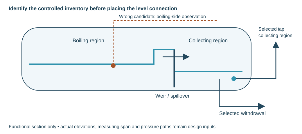
Figure 6.8. A functional kettle section separates boiling inventory from collected liquid beyond the weir. The selected collecting-level connection must communicate with that region. The dashed candidate before the weir observes a different inventory. No dimensions, operating levels or acceptance result are assigned. Structured regions and connections.
Put measurement and distribution where the phase permits them
Liquid near its boiling condition can flash when pressure falls. An elevation rise or resistance before a measurement or control device can therefore change the phase entering it. A device and calibration intended for liquid service should not be assumed to retain the same function when the incoming flow becomes two-phase.
Consider a liquid draw-off whose route rises before its meter and control valve. The route can use available liquid head and introduce loss before those functions. An alternative can keep the measuring/control section at a lower elevation and place the later rise downstream, or cool the stream before the selected measurement. Evaluate the actual pressure, temperature and losses. Lower elevation can provide head, but a geometric sketch alone does not prove that flashing is prevented under every condition. Measurement and control develops the device-specific basis.
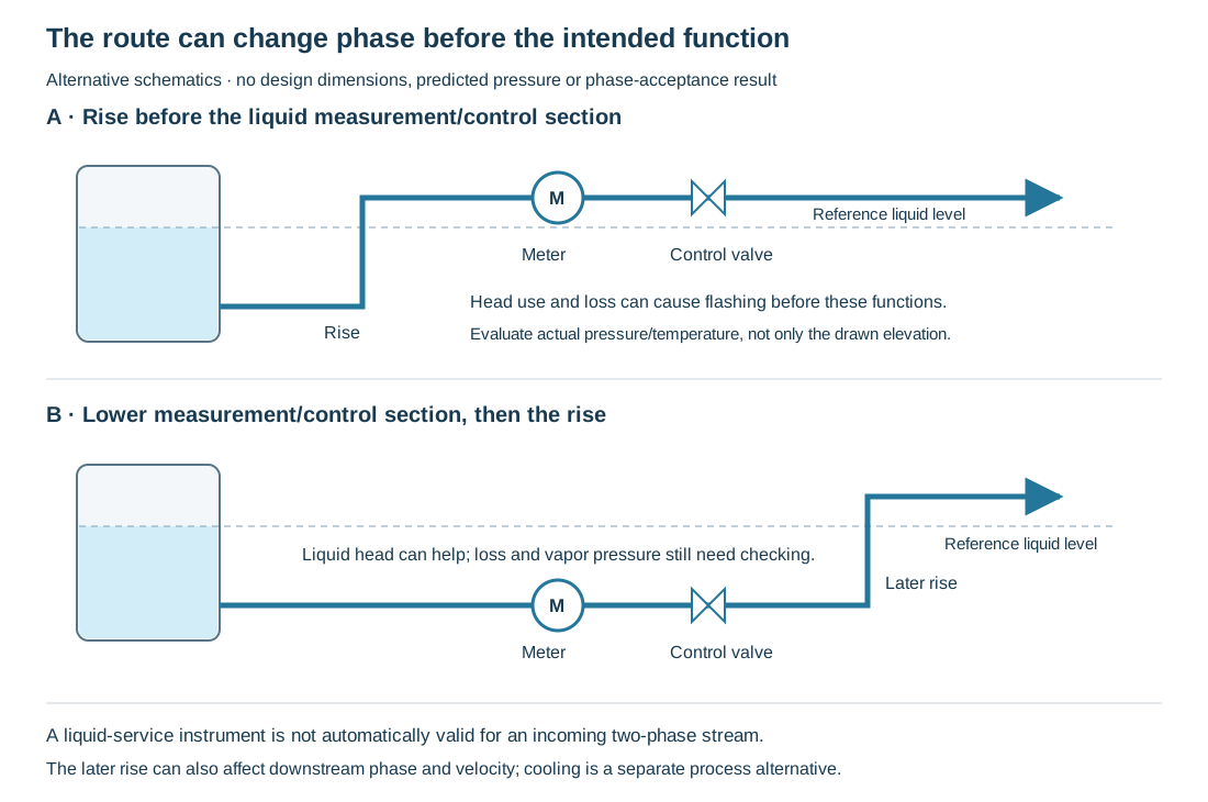
Figure 6.9. Two alternative function-only routes from liquid near its boiling condition. The first rises before the selected liquid meter/control section. The second places that section below the reference liquid level before a later rise. Actual head, loss and vapor pressure still need evaluation. Neither schematic predicts pressure or declares phase adequacy. Structured flow paths.
Distribution to parallel equipment is another phase-sensitive function. Liquid momentum and vapor resistance preference can send different mixtures through apparently similar branches. Equal total quantities or equal pipe sizes do not establish equal vapor/liquid fractions. Develop the incoming approach, splits and branch paths for the required distribution. Carry the actual pressure-loss and phase conditions into evaluation.
Hydraulic balance is the objective. Geometric symmetry is one means of pursuing it under a selected basis. For heater and exchanger distribution, an adopted practice may require particular symmetry and approach geometry. Another basis can permit a different geometry where outlet hydraulic balance is established. Do not silently substitute one rule for the other. Preserve the selected inlet and outlet requirements and evaluate the participating phases rather than choose a universal sketch.
Flow-regulating valves can adjust branch resistance or serve a selected isolation function. They do not automatically distribute liquid and vapor correctly at an upstream junction. An outlet temperature can help an operating comparison for matched cells and conditions. It is not by itself proof of equal flow under unequal duties or phases. Coordinate the distribution method, measurement and operating adjustments with the equipment's actual service.
Air cooling adds airflow, drainage and cell movement
An air cooler passes the process fluid through tubes while air flows around an extended surface. Fans move the air. In a forced-draft arrangement they are below the tube cells. In an induced-draft arrangement they are above. The selected fan, tube and frame configuration determines access and the space around the cooler, as well as the cooling function.
A cell is a set of tubes and connections with its specified passes. An even-pass arrangement can put inlet and outlet at the same end. An odd-pass arrangement can place them at opposite ends. The nozzle positions therefore affect the return route and equipment elevation. Reorienting a cell or changing the pass arrangement can improve piping but also changes the selected thermal and equipment configuration, so it requires coordinated evaluation.
Condensing service needs a path for the formed liquid. An overhead-vapor line can begin condensing before it reaches the cooler. A pocket can retain liquid and deliver a slug to the equipment rather than a controlled incoming mixture. Keep the selected inlet and outlet drainage paths associated with tower, cooler and accumulator elevations. Evaluate path behavior in operation and shutdown. A rack-mounted cooler can suit those relationships while adding structural, lifting and access interfaces.
Multiple cells require distribution appropriate to the number of connections, phases and duties. Center-fed or staged headers and selected regulating arrangements are alternatives, not one rule for every number of cells. Inlet and outlet fluid conditions can differ substantially when condensation is extensive. Do not impose identical manifolding merely because the equipment has matching rows of nozzles. Do not remove a selected symmetry requirement merely because another service did not need it.
Inlet piping can be hotter than the outlet piping, creating differential movement. The cells and frame have their permitted movements and restraints. Attached headers and supports must be evaluated with them. A common frame does not make every nozzle a fixed point or guarantee that opposite headers grow together. Compare normal, startup and relevant partial-service conditions through analysis and supports.
Humidified or other water-assisted cooler forms add water inventory, circulation and weight. Their elevation, foundation and drainage demands differ from a dry rack-mounted unit. Fan access, tube servicing, header plugs and major section removal also require actual work paths. Layout and access supplies the common spatial method, while this equipment account supplies the nozzle, drainage and maintenance mechanisms that method must preserve.
The approach to a junction can separate the phases
Parallel exchangers require the intended liquid and vapor delivery to each participating unit, as well as an acceptable total flow. At a two-phase junction, those are different questions. Liquid momentum can favor a continuation of the incoming route while vapor responds differently to the branch resistances. Similar branch diameters do not establish comparable phase fractions, and similar total flows do not establish comparable heat-transfer conditions.
The paired geometry below compares two approaches. One continues toward exchanger B with a side route toward A. The other meets the branch midway between the exchangers. In the first construction, the two outlets do not present the same approach to the incoming mixture. In this example with exchangers intended for matching duty and pressure drop, liquid favors B and vapor favors A. That is the mechanism being illustrated, not a prediction of the actual fractions at an unspecified junction.
In the second construction, the incoming stream meets opposed branch routes with comparable geometry.
This removes the illustrated straight-through preference and supplies a basis for evaluating distribution.
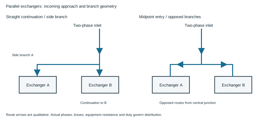
Figure 6.10. The first route gives B a continuation of the inlet approach and A a side branch. The second enters midway between A and B and divides into opposed routes. Arrows show routes only. Their thickness and spacing carry no quantities. No equal-flow or equal-phase guarantee is assigned. Structured junction alternatives.
Evaluate the comparison with actual inlet pressure/temperature/phase, approach direction, branch elevations/losses, equipment duties/resistance and required distribution range.
A phase change along one route, different exchanger resistance or a changed operating combination can invalidate a comparison based only on matching outside pipework. Carry those conditions with the phase-path account and fluid-state description.
An air-cooler manifold connects a row of process nozzles through common inlet and outlet headers. The inlet row and outlet row serve different states when substantial condensation occurs in the tubes. Their similar appearance does not establish that the same symmetry requirement applies to both. An inlet carrying vapor and liquid requires a distribution account for those phases. An extensively condensed outlet requires its own collection, pressure-loss and drainage account. Retain the supplier's passes and connection locations while evaluating both.
Three historical plan arrangements make the header choices concrete. The first feeds one end of the inlet header and collects from the opposite end of the outlet header. The second enters the inlet header at its center and takes the outlet from the center of the corresponding collecting header. The third divides the incoming line between two separately center-fed header groups, then combines the group outlets. These are alternatives for process-fluid distribution and collection. The diagrams do not add an auxiliary circuit or an operating-control arrangement.
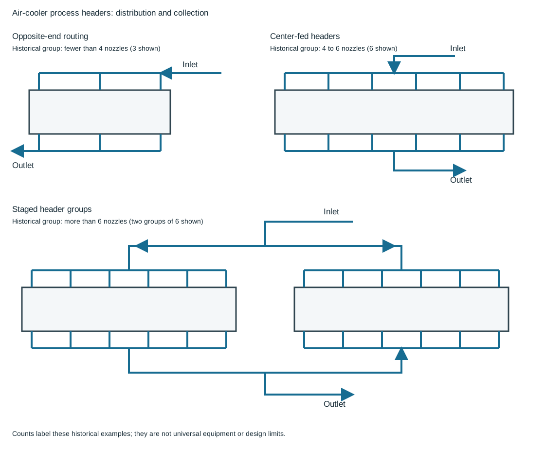
Figure 6.11. The historical grouping labels are fewer than 4 nozzles, 4 to 6 nozzles, and more than 6 nozzles, counted along each process-nozzle row. The illustrated rows show 3, 6 and two groups of 6 respectively. Those counts define these examples rather than universal design limits. Arrows identify inlet distribution and outlet collection. No flow quantities are encoded. Structured manifolds and nozzle groups.
| Arrangement in the comparison |
Connection relationship to inspect |
| Opposite-end feed and return, illustrated with three nozzles per row |
The inlet approaches from one end; the collected outlet leaves from the other. Follow each complete equipment path rather than comparing inlet branch lengths alone. |
| Center-fed headers, illustrated with six nozzles per row |
The center connection divides toward both ends of the inlet row, while the outlet branches collect toward a central connection. Check the two halves and the individual branches. |
| Staged groups, illustrated with two groups of six nozzles per row |
The first split feeds each group header; each group distributes again. The outlet groups collect locally and combine at a further junction. Retain both stages in the hydraulic and phase account. |
The selected grouping basis uses opposite-end routing for up to three nozzles and staged groups with up to six nozzles each. These labels help read the examples. They do not choose the permissible nozzle count for another cooler. The required phases, duty, pressure losses, supplier connections and adopted design basis decide whether a corresponding arrangement is useful. A compact manifold can still have unequal branch behavior, while a geometrically regular one can still divide a mixture poorly.
Review the manifolds in their operating and mechanical states together. Condensation before the inlet can create liquid that needs a draining route into the cells. Collection after the cells must preserve the selected path to the accumulator. Hotter inlet piping and cooler outlet piping can move differently. The permitted movement of the cells in their frame remains part of the supplier interface.
Verify branch flexibility, supporting points and nozzle reactions against that movement. Neither a center entry nor a staged split establishes free movement or adequate pressure loss by itself. Changes to the participating cells or their service reopen the distribution, collection and movement assumptions.
A tube plug and a header access plug close different interfaces
Tube servicing in a plug-type header uses an opening in the outer header wall aligned with a tube end. A header-box access plug closes that outer opening. A tube plug instead seats at the selected tube end and excludes that tube-end flow path from the header. The same word “plug” therefore names two parts with different locations and purposes. Identify the physical interface before applying any closure specification.
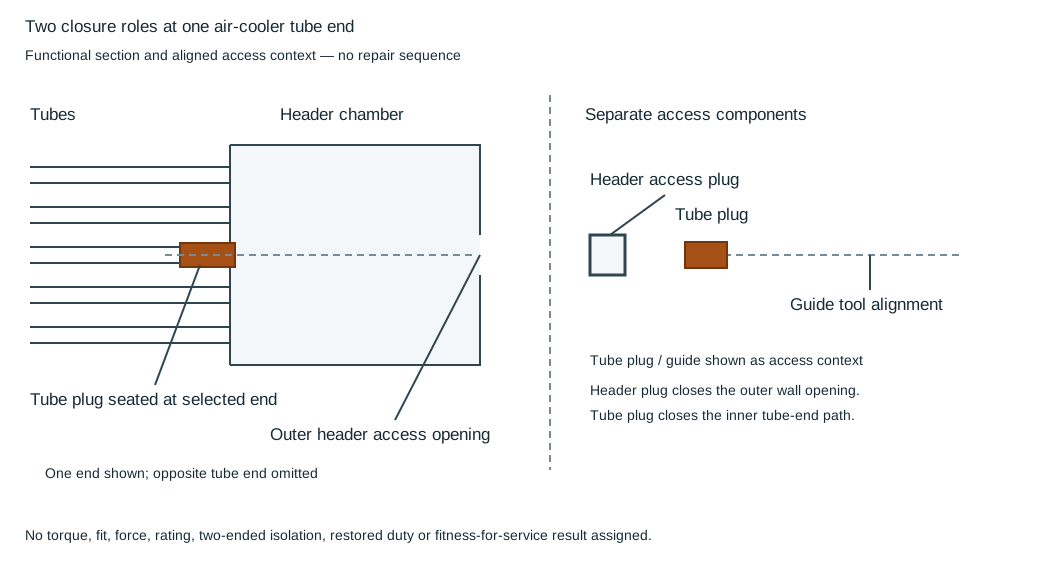
Figure 6.12. The left panel shows the tube-end plug seated at one tube while the header access opening is shown open. The right panel identifies the separate header access plug and a guide tool aligned with that opening. The juxtaposition explains location and access, not an insertion sequence or repair instruction. Only one tube end is represented. Structured closure roles.
| Component |
Interface and function |
Basis to keep with it |
| Header access plug |
Closes the access opening in the outer header wall; restores that local header-boundary closure |
The selected header thread, material, gasket and assembly requirements, including the applicable torque basis |
| Tube plug |
Seats at the selected tube end; excludes that local tube-end path from the header |
The selected equipment's qualified tube-repair and exclusion basis, with its own plug and verification requirements |
A guide tool shown through the access alignment explains how the inner tube end can be reached through the outer opening. Its presence does not make the tube plug part of the header-plug joint. The special assembly account addresses header-plug closure requirements. Those requirements cannot be transferred to the tube plug because the part names resemble each other.
The one-end section supplies no plug taper, fit, material, insertion force, pressure rating or repair procedure. It also does not establish isolation at both ends of the tube, restored cooler duty or fitness for service. Keep identification of the two closure roles separate from authorization of a repair. Any accepted tube exclusion changes the equipment's participating flow paths. It can require reassessment of the thermal, hydraulic and integrity basis under operating integrity and intervention. Preserve the applicable closure checks and return-to-service record for the actual equipment.
A condensate pocket can consume a pressure-control path's driving pressure
A hot-vapor bypass around a condenser can admit overhead vapor to an accumulator through a pressure-control valve. Its purpose is to influence accumulator pressure, while the main path removes heat and delivers condensed fluid. Vapor in the bypass can itself condense as the line loses heat. A retained liquid pocket then adds a head barrier to the small pressure difference driving the bypass. The resulting problem can be loss of the control path's useful flow, even before a liquid slug reaches the cooler or vessel.
Trace the pressure budget from the upstream bypass takeoff A to the accumulator connection B. At a specified flow and state, define the remaining pressure available against a liquid barrier as
All terms are pressure differences in the same unit and on consistent pressure references. The line term represents the selected flow resistance outside the separately stated valve loss. For a static, uniform liquid barrier with effective vertical height , density and gravitational acceleration , its head is . The height is the vertical difference across the retained liquid barrier, not total pipe length. Compare this head with the available pressure under the same state. A nonpositive remaining budget cannot drive the assumed flow through an added positive head barrier.
A liquid barrier consuming the remaining budget eliminates the assumed useful flow; a smaller head still reduces the pressure available for control. This comparison establishes no allowable pocket height or control margin.
A continuously draining bypass is one way to prevent that retained inventory. In the selected arrangement the valve sits above the accumulator and the route drains toward its connection. Another geometry needs an evaluated means of avoiding or removing the liquid barrier while preserving the containment and pressure-control functions. Check condensation, actual connection levels, valve capacity and authority, pressure fluctuations and the participating phases.
The pressure budget neither selects a valve type nor substitutes a static calculation for two-phase flow or transient evaluation. Flow and control provide the neighboring methods. Structured pressure-budget method.
Identify where cooling water meets the air or tubes
Water-assisted cooling describes different physical paths. In one arrangement, incoming air passes through a separate water-contact section that washes, cools and humidifies it. A mist eliminator lies between that section and the process-tube cell. The process fluid remains in its tubes. The intended water contact occurs in the air-conditioning section. In another arrangement, water is applied directly over the tube surface, combining evaporative action with the air-side heat transfer at the process cell.
That difference changes the questions for materials, inspection and operation. The separate section has water distribution, collection and mist-removal functions whose condition affects the air reaching the tubes. Mist carryover can defeat the intended separation. Direct wetting intentionally exposes the tube exterior to the selected water and its deposits. Thus external corrosion, fouling, drainage and wet/dry transitions participate directly in the cell's service. Both forms add water inventory, supply and circulation demands, but their water chemistry and inspection boundaries should not be collapsed into one generic cooler property.
A selected winter arrangement can bypass the water-contact section and send air directly to the cell through changed louver positions. Treat that as a defined operating configuration: identify the actual air route, water-system condition, fan/control action and expected duty. A dry bypass does not establish that all required winter performance or freeze protection is available. Loss of water, fan changes and partial operation require their own thermal and process evaluation. Keep these conditions with the equipment selection. Do not assume a device called humidified has one fixed state throughout the year.

Figure 6.13. Two function-only water-contact alternatives. The first conditions air separately and removes entrained mist before the process cell. Its selected dry bypass changes the air route. The second intentionally wets the tube exterior. Arrows show functional paths, not guaranteed performance or an operating sequence. Structured paths and states.
Compare both bounds of a preliminary rack envelope
A rack-mounted tube cell has to reach its supports while leaving useful inlet and outlet connection paths. One adopted preliminary arrangement compares rack width with tube length using
In this equation, is the cell's tube length and is rack width in feet, measured in the illustrated span direction. The lower bound belongs to the selected support geometry. The upper bound preserves the arrangement's nominal total 2 ft connection allowance. These are competing bounds under that particular planning method. They are not a universal rule for cooler frames or every nozzle layout.
Replace the preliminary envelope with the selected supplier's actual frame, support, nozzle and maintenance geometry before commitment. Structural capacity, cell movement, flange/valve access, airflow, lifting and rack routing remain separate evaluations. A feasible numerical width says only that the candidate meets these two planning bounds. A connection projection or different support form can invalidate their applicability without changing the tube length. Structured preliminary geometry and checks.
Fired-heater passes combine heat transfer and flow resistance
A fired heater transfers heat from combustion to the process through tubes. A radiant section receives the principal radiated heat. A convection section uses the hot gas on its path toward the stack. Vertical and horizontal or box arrangements place burners, tubes, ducts and access differently. Some selected heaters have both sections, while others have a radiant-only arrangement. The external piping must serve the actual pass and nozzle configuration.
The heater's required heat transfer and allowable pressure loss interact. Sending fluid through more tube length can increase exposure to heating but also increase loss. The equipment designer divides the flow into passes suited to the duty. Each pass has its selected inlet, outlet and flow requirement. The external system must supply that division without assuming that equal nozzle sizes alone establish equal duty.
For parallel passes intended to carry comparable flow, unbalanced pressure loss can create unequal operation. Two-phase service adds the possibility of phase separation at a junction. A selected symmetrical manifold can make lengths, fittings and branches correspond, while balancing valves or other selected controls address their own functions. Geometric symmetry must still be interpreted with the required phases and process conditions. A valve that balances total flow does not necessarily correct an upstream phase split.
The inlet and outlet criteria must remain attributable to the adopted basis. A practice can require geometric symmetry at both inlet and outlet for its two-phase heater arrangement. Another requires inlet symmetry but permits an outlet that is hydraulically balanced without identical geometry. These approaches should not be blended into a rule that symmetry is either always necessary or never necessary. Resolve the applicable criterion and evaluate the actual transfer-line behavior and heater performance.
A vendor-furnished inlet manifold can simplify the field connection but transfers another load and movement interface to the equipment. The supplier needs the piping reactions and any support or spring movement that the manifold connection must accommodate. Independent field routing should not force a furnished manifold into a different geometry. Equipment tubing, manifold and field pipe can have different materials, walls and design bases. Inspect the actual transition and fabrication requirements rather than infer compatibility from nominal size.
Individual pass valves and flow indications can put an operator in a useful position to compare and adjust the selected distribution. The indication should be visible while the related valve is operated. The measurement purpose can be relative balancing rather than custody accuracy, but that does not eliminate the device's installation and phase requirements. Instrumentation develops the distinction, and connections develops the physical taps and branches.
Heater location and elevation also affect burners, maintenance and connected flow. Preserve access to firing and inspection positions, tube removal and the selected explosion-door or relief arrangement. A tube or manifold connection can move with the hot equipment. Arrange supports and piping flexibility for that movement rather than treat the heater shell as one fixed terminal. The stack, combustion-air and fuel interfaces belong in the actual selected system. This account does not derive stack height, burner duty or a combustion-control specification from a typical equipment sketch.
The tube support reference directs movement into the field interface
A furnished heater manifold and an independently supported field ring create different interfaces. A furnished manifold already participates in the supplier's equipment geometry and support arrangement. Its external reactions and permitted movement must be communicated across that boundary. An independent bottom ring can instead be supported from the heater structure or from grade. Those alternatives introduce different structural reactions and relative movement between the ring, heater and field pipe.
Identify where the process tubes are supported before assigning nozzle displacement. For a bottom-supported vertical tube, axial thermal growth proceeds away from the bottom reference, upward into the heater. A tube whose support reference is elsewhere can move its bottom connection differently and impose that displacement on the external manifold. The selected support changes the movement input to the piping evaluation. Calling both connections heater outlets does not make them equivalent. A top connection is another equipment arrangement with a different external route and reference relationship.
Draw the tube support reference, the ring supports and the connection between them in the defined cold and hot states. Compare differential movement and load transfer rather than assuming that a grade-supported ring follows heater steel. Coordinate the actual tube-support design with the heater supplier, including permitted tube growth and equipment attachments. A bottom reference can reduce a particular downward movement demand but does not guarantee acceptable nozzle forces or eliminate piping flexibility work. Materials, temperatures, support contacts and the selected structural restraint still govern the combined system through analysis and supports.
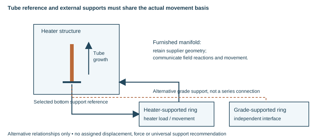
Figure 6.14. A selected bottom tube-support reference directs tube growth upward. Heater-supported and grade-supported external rings have different movement/load interfaces. The arrows indicate relationships to evaluate, with no displacement, force or universal support recommendation assigned. Structured entities and movement relationships.
Develop the fuel, air, flue-gas and process paths together
Keep fuel/atomizing services, combustion-air, flue-gas and contained-process paths distinct. In a natural-draft installation, stack, furnace and burner-register resistance determine the pressure profile. A damper changes flue-path resistance; draft-gauge position determines what pressure is observed. Illustrative water-column readings are not universal setpoints.
Changing stack height, duct resistance or heat-recovery equipment requires reevaluation of draft and flow. It does not automatically establish that a fan must be added or that the former settings remain adequate.
Combustion-air preheating can recover heat while adding another configuration. One arrangement transfers heat from flue gas to incoming air in a preheater. A forced-draft fan delivers air toward the burner plenum. An induced-draft fan draws gas through the recovery path.
Another circulates hot oil from convection-section heating through an air-heating coil and back through its selected tank/pump loop. The first adds substantial gas/air duct and fan interfaces. The second adds circulating-liquid, pump and inventory interfaces.
Compare actual heat recovery, flow resistance, utilities, maintenance space and loss-of-supply states before selecting the arrangement. The flow paths identify the alternatives more clearly than assigning them one universal preheater classification.
Fuel and steam services have several different jobs around a burner. In a selected oil-firing arrangement, atomizing steam accompanies oil at the burner to aid dispersion. A coordinated heating/insulation arrangement maintains the oil condition required for useful delivery.
Pilot gas supports ignition. Main fuel gas supplies firing duty. Low points in a fuel-gas path can collect condensate, so the selected drainage and collection destination belong in its service basis. A historical drain to flare is one arrangement, not permission to connect every fuel drain to any available header.
A header box encloses accessible return fittings and plugs separated from the furnace interior by an insulated tube sheet. Its access permits inspection, cleaning and replacement. In a selected detail, a drain with a seal loop and cleanout provides an observation path for leakage, while snuffing steam provides a fire-suppression interface. Observation and suppression are different functions. Neither proves that a leaking process connection is acceptable or that the selected protective system is complete.
Table 6.2. Similar small service connections can preserve different functions.
| Connection or assembly |
Physical purpose and consequential interface |
| Atomizing steam with fuel oil |
Selected burner fuel dispersion; pressure, flow, oil condition and drainage |
| Snuffing steam |
Selected suppression destination, local/remote operation and supply availability |
| Soot-blower steam or air |
Cleaning external convection surfaces; moving lance, hose or fixed piping and withdrawal |
| Decoking steam/air connections |
A defined process-tube intervention configuration, distinct from normal product flow |
| Header-box drain/cleanout |
Selected leak-observation and collection path with access |
| Draft gauge and damper operator |
Pressure observation and flue-path adjustment at their identified locations |
A burner management package adds sensing, sequence and shutoff functions around the physical burner. Its selected interfaces can include purge conditions, pilot/main-flame observation, admission valves and a response to unsafe heater conditions. Trace those functions across package and field boundaries, including supplies and the operator/control position. A historical manual-ignition drawing or a claim that one burner tolerates many fuels does not establish another installation's permitted fuel, control or protective basis.
Place the operating position so the relevant observation remains available during action. A flow indication used while adjusting a pass valve should be visible from that valve. A burner valve near a peep door can permit the selected flame observation. An oil gun needs its axial removal path, and a retractable soot blower needs carriage and lance travel outside the convection section. Floor-, wall- and roof-fired arrangements therefore impose different working levels and furnace elevations.
Draw those tasks alongside the piping and ducts. A single generic heater clearance cannot represent them.
Soot and coke create different maintenance configurations
Soot deposits on the external tube surface. Coke accumulates inside the process tubes in susceptible service. Both can reduce the useful heat-transfer function, while internal coke also affects flow. Their removal methods and connections are different. Recognizing the deposit location explains why a soot-blower installation does not supply a complete decoking arrangement.
Soot blowers need their specified supply, drainage, motor or actuator access and lance removal path. Steam routing and condensate removal matter because liquid should not be carried into the hot equipment in a manner that damages it. A vendor-supplied assembly can include piping, while another installation leaves those connections to the field design. Verify the actual scope and keep the movement and removal envelope available.
Steam-air decoking changes the process-tube service and introduces temporary connections. The source-supported arrangement uses steam action and then controlled burning to remove internal deposits, with the selected cooling or other-pass protection arrangements. That description explains why steam, air, water and discharge paths need planned connection and access. It is not an execution recipe. Hydrocarbon removal/isolation, temperatures, flow limits, sequence and monitoring belong to the validated procedure for the selected heater and service.
Some decoking connections are included in the original equipment or piping design even when the associated temporary lines are installed only for the activity. Define where they connect, how temporary piping is supported and handled, and which normal-service connections are restored afterward. The decoking state can impose a different movement and thermal range from production. Analysis, supports, readiness and intervention develop those linked evaluations and restoration needs.
A modification can change feed, operating temperature, pass distribution or tube arrangement. Those changes can affect deposit propensity and suitability of the existing cleaning/decoking path. Reconsider the equipment and external system together. Successful previous operation is evidence for its former conditions, not proof that every new duty preserves them.
Follow both ends of the process pass through a connection change
A decoking connection changes the service of the process tubes. The layout must distinguish the tube pass, the normal process inlet and outlet, the removable connecting pieces and the temporary end connections. A recognizable inlet connection alone does not define the resulting state. The other end must have an identified boundary and a corresponding route for material leaving the pass. Keep that end-to-end account with the selected heater, service and intervention basis.
The boundary model below considers one process pass with a removable connection at each end. In production, the pass connects to the normal process inlet and outlet through those pieces. In the separately defined intervention configuration, the normal process connections are disconnected at the identified joints and their remaining ends have the specified closures. Temporary connections occupy the selected pass-end interfaces. The tube pass remains the same physical object, while the external connection identities change.
This is an illustrative configuration comparison, with both ends defined together. It is not an operating lineup or a sequence for moving the connecting pieces.
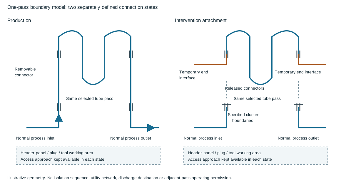
Figure 6.15. The blue path identifies the tube pass and its normal process connections. The orange marks identify removable connection positions in the separate intervention configuration. The detached process ends and their specified closure boundaries remain visible. Temporary end connections are shown only at the equipment interface. No supply, control, quench or discharge circuit is defined. Structured connection identities and states.
A swing elbow is one way to make a physical connection removable and redirectable. A removable spool is another. The required disconnection points, bolt access, supporting arrangement and place for the released piece should be apparent in the layout.
When the connector is removed, keep the remaining pipe supported. Evaluate the temporary attachment and its loads under its actual thermal and pressure conditions.
The small diagram establishes which interfaces change. It supplies no isolation effectiveness, load allowable or movement envelope.
Header-box panels and tube-header plugs introduce another access task. The panel opening must be reachable, the removed panel needs a handling position, and the plug or cleaning-tool approach needs its own working space. These paths can be obstructed by a connector that fits during production. Treat the tube-end working area, access door and personnel approach as part of the intervention geometry. Temporary piping that crosses a platform edge also requires the selected protection and subsequent reinstatement. A removed handrail is not a complete access solution.
| Interface in the one-pass comparison |
Connection or access question |
Restoration evidence to retain |
| Normal process inlet and outlet |
Which joints release the pass from its production piping, and what closes the remaining process ends? |
Intended process route, actual joint and closure identities, affected examination and assembly checks |
| Pass-end temporary attachment |
Does it connect to the selected end and remain within the adopted pressure, temperature, material and load basis? |
Removal or retained-item disposition and the verified final end connection |
| Swing elbow or removable spool |
What must move, what supports the remaining pipe, and where is the released piece held? |
Connector reinstatement, orientation, joints and support condition |
| Header-box panel and tube-header plug |
Can the panel, plug and tool be handled through their required paths? |
Replaced closure parts, applicable joint checks and access-panel reinstatement |
| Platforms and personnel route |
What temporary obstructions or protection changes accompany the attachment? |
Cleared work route and reinstated selected protection |
The comparison supplies no authority to keep a neighboring pass in production during decoking. Hydrocarbon removal and isolation, tube-temperature protection, operating limits and procedure validation belong to the selected intervention basis. Plan physical connections so that this basis can be executed and checked. Then use intervention and restoration records to preserve the actual final containment and service configuration.
Connection alternatives and reverse flow are separate choices
Temporary attachments can meet a heater nozzle, a dedicated heater-tube connection or an external interface opened by a swing elbow or removable spool.
These choices put the releasable boundary in different places. A connection incorporated into the original equipment does not mean its temporary external piping remains installed during production. A convenient outside flange does not establish that the tube pass has the intended internal route.

Figure 6.16. The upper sketches locate different attachment boundaries at the process-tube end. They are independent alternatives. The lower sketches show the same abstract pass traversed in opposite directions as separately defined intervention states. Arrows stop at the end interfaces and show direction only. The supply and collection arrangements needed to establish either state are outside this drawing. Structured physical alternatives and direction states.
A dedicated connection on the heater tube can change the relationship between the normal nozzle and temporary attachment. A connector exchanged at the nozzle flange gives a different relationship. The selected drawing must identify both relationships and the actual closure of the unused path. With an external swing elbow or spool, identify the fixed joint faces and the connector's two ends. Changing its position changes which fixed interfaces are joined. Do not infer a common interchangeable part merely because two alternative sketches show an elbow.
Forward and reverse decoking flow through a pass are also distinct configurations. Reversing the direction changes which tube end receives the incoming stream and which end discharges the removed material. It therefore changes the duties of the end connections and their attached paths even when the tubes themselves remain unchanged. The selected arrangement must accommodate the required direction and the changed temperature, material transport and pressure conditions. A two-headed arrow through the coil expresses a possibility. It does not supply the connections or validated procedure that establish each direction.
Keep the process-tube path separate from the fate of the removed coke and associated fluid. An accepted intervention arrangement needs an identified collection or discharge interface and an evaluated receiving destination. Historical sewer, pit, drum and stack examples do not establish a permitted destination for another service. Likewise, a sample or erosion-resistant fitting on a particular discharge arrangement belongs to that arrangement's actual material transport and receiving basis. Its presence does not prove that another temporary end connection tolerates the same conditions.
Record the selected pass, connection alternative and direction with fixed interfaces, removable parts, access paths and restoration requirements. Confirm inlet/outlet compatibility, final process routing, joints, closures and support/protection through technical continuity.
Heat recovery introduces a circulation loop and another operating state
A steam-generation circuit around a convection coil or transfer line exchanger connects heat input to phase change and circulation. An elevated steam drum collects the generated steam and provides a water supply to the downcomer. Heating in the coil or exchanger creates a lower-density vapor/liquid mixture that returns through the riser. The difference between the water-side and mixture-side head can drive natural circulation, while resistance consumes that driving pressure. Drum elevation alone is not proof that the loop circulates adequately.

Figure 6.17. A function-only natural-circulation arrangement: water descends from the drum to the heated equipment and a vapor/liquid mixture returns through the riser. The contained hot-product path supplies heat across a separating surface. No elevation, density, duty, flow or circulation adequacy is assigned. Structured flow relationships.
Keep the two sides of a transfer line exchanger identified. The hot process product follows its own pressure boundary. Water/steam receives heat through the exchanger surface. In a pyrolysis arrangement, the product can pass from convection preheating through a crossover and radiant heating, then through the transfer line exchanger. Repositioning the exchanger changes both that process route and the drum/downcomer/riser connections. Its support lugs, head-removal trolley and bundle or tube work also need their selected paths.
Avoid unintended pockets and evaluate the slope and phase behavior of each actual circulation connection. Long horizontal mixture runs can introduce unfavorable phase distribution or slug behavior. A loop added for thermal flexibility changes resistance and phase geometry. Changing the drum or exchanger elevation changes head and structural/access needs. Compare routing, support and elevation alternatives through the same operating basis.
The selected normal, startup and shutdown conditions may have different heat input, inventory and vapor generation. A pump-driven circuit supplies another circulation mechanism and should be evaluated as a forced-circulation configuration.
The hot product transfer line has a different concern. Susceptible service can form coke in a long route. A shorter route or selected quench near the heater outlet can address that propensity while still needing thermal flexibility, terminal loads and process evaluation. Planned cleaning flanges provide a physical intervention interface. They do not establish a cleaning interval or permit an unreviewed opening of the line.
Waste-heat recovery after a gas turbine introduces an additional heat-source boundary. Turbine exhaust can supply the recovery equipment in the normal selected state. A particular arrangement can also use duct burners when the turbine is shut down. That alternative changes fuel, combustion-air/flue-gas and control requirements. The presence of a burner does not guarantee steam availability following every turbine or utility loss.
Establish the permitted heat-source states with the drum, boiler, feedwater, superheater and bypass arrangements. Verify the actual supplies and selected operating controls. The meaningful comparison is continued function under defined conditions, rather than a generic claim of redundancy.
Storage must contain the inventory in its applicable pressure and temperature condition and permit transfer, observation and maintenance. A fixed-roof low-pressure tank, a floating-roof tank, refrigerated or other low-temperature storage and a pressure vessel impose different boundaries. The same nominal volume does not establish the same foundation, piping or protective arrangement.
A cone or other fixed roof remains in place above the liquid. A floating roof moves with the level and changes the vapor-space relationship. The roof's travel, associated seals or supports and operating limits belong to the selected form. External access and instruments must accommodate that arrangement. Do not treat a moving roof as a fixed attachment location without its design basis.
Low-temperature storage can retain liquefied gases near their boiling condition at the selected pressure. Heat input, pressure, material suitability and the surrounding foundation and containment become consequential. The storage temperature is a service input, not a universal value attached to a product name. Insulation and cold-service supports need their own physical and material basis. Ordinary warm metallic-support criteria cannot simply be extended to cryogenic service. Materials, special services and thermal protection develop those requirements.
Horizontal pressure vessels and spherical forms provide another storage arrangement for the selected pressure service. Their support, inspection and piping movements differ from a flat-bottomed atmospheric tank. A vessel type or wall shape does not establish a complete pressure-protection system. Pressure design and relief carries the selected inventory and upset conditions into the governing basis.
Choose storage dimensions with the site, foundation and operating inventory together. A taller, smaller-diameter tank and a lower, larger-diameter tank can use land and foundations differently. Commercial or shop-fabricated sizes may be useful where applicable. Large field-fabricated storage still needs its actual service and site design. The next methods make the volume and displaced-space parts of that comparison explicit, without supplying a universal tank or dike design.
Separate liquid volume from final tank height
Determine liquid depth from the required cylindrical inventory and actual inside diameter. It does not establish final shell height: roof construction, operating levels, unused capacity and selected allowances remain separate design inputs. A nominal shell chosen by rounding liquid height alone can omit them.
For containment displacement, use the part of a foundation or berm below the evaluated retained-liquid level. Partial submergence cannot be represented by subtracting the whole solid volume. The geometry must match the actual foundation; a circular-frustum method does not describe an arbitrary rectangular foundation or dike. Keep stored-liquid inventory and submerged solid displacement on their respective sides of the usable-volume account.
Gross enclosure volume is not usable containment
Secondary containment has a function separate from normal storage: it provides a defined space for a release scenario under its adopted basis. The required retained inventory, participating tank failure or spill, other liquid inputs, freeboard and exclusions must be established for the actual service. A historical largest-tank sizing rule does not establish all current requirements for every multi-tank area or liquefied-gas facility. Where the governing basis adopts NFPA 30 for flammable and combustible liquid diking, retain its selected edition, service scope and project conditions. The geometric method here does not extend that basis to all refrigerated or pressure storage.
The usable space at a selected retained-liquid level can be expressed as
In this equation, is the level measured from the defined datum. The enclosure term is the interior geometric volume below that level. Displacement counts the relevant solids and structures occupying that volume under the selected release state. Already-occupied volume represents other liquid whose treatment is specified in the account. Avoid double-counting an item or a fluid. The actual required capacity and selected allowances remain a separate comparison with usable volume.
The method becomes more involved when the interior floor slopes, the wall is an earthen slope or several structures are present. Use the actual volume below each evaluated level or a correctly scoped geometric method/chart. A single plan area multiplied by height can be wrong when the cross-section changes with elevation. A chart for one slope and datum cannot be applied to another enclosure without examining its assumptions.
For multiple tanks, identify what remains inside the enclosure in the selected release state and which volumes the governing basis counts as displaced or available. The treatment of a tank involved in the release should not be invented from its normal operating outline. Soil berms, foundations and other tanks can consume space that a gross-area calculation overlooks. Inventory, displacement, floor grade and the selected retained level must describe the same configuration.
Earthen dikes, concrete walls, secondary tank walls and combined or double-containment arrangements use land, access and failure boundaries differently. An earthen form needs its selected material, slope and support. A compact wall can constrain working space and penetrations. A second boundary can serve a selected additional containment function, especially where the service and nearby exposure make that function consequential. Its presence does not automatically establish independence or an adequate capacity.
Layout coordinates placement and access. This chapter develops the explicit capacity and equipment-state account.
Drainage is part of that boundary. Minor spills, rainwater and selected other inputs have to follow the adopted collection and disposal route without defeating the intended containment. Establish how drains, sumps and penetrations behave in the release and operating states. An open flow path may drain a normal area while also releasing the inventory the enclosure was intended to retain. No capacity arithmetic can compensate for an unexamined boundary or an incompatible fluid/service condition.
Foundations and transfer piping must tolerate the selected states
Tank foundations can use a ring wall, compacted fill or a selected concrete arrangement. Their geometry and expected movement affect piping, access and the capacity account. Civil and geotechnical design establishes the actual supporting conditions. The piping arrangement needs those conditions rather than assume that a tank and adjacent sleeper or rack remain at one relative elevation.
Low-temperature foundations add a thermal function. Described alternatives use an elevated concrete base with air space or a foundation with an embedded heating arrangement for the selected cold-release concern. These are particular foundation designs, not a universal instruction to heat every storage pad. Their access, supply, inspection and failure states should remain connected to the stored service and selected containment system.
Settlement can change the tank nozzle relative to pipe supports, a pump or an enclosure penetration. A filled tank, an empty tank and an installed reference can impose different displacement conditions. Route and support the transfer piping for the evaluated relative movements. A fixed bridge across the nozzle and another foundation can turn settlement into terminal load. Analysis and supports develop that evaluation with the actual movement and acceptance basis.
Locating a pump inside or outside a dike changes both access and fluid routing. A route over a wall can avoid a penetration but introduce a rise, another suction-head demand or a potential vapor pocket. A penetration can simplify the route while requiring its selected containment detail. Evaluate the lowest operating liquid level, pressure/vapor condition and loss with the suction-head method. Also evaluate the boundary and maintenance task. Neither outside placement nor an over-wall route is a universal preferred solution.
Tank manways, heaters, level instruments, roof access and piping have different maintenance paths. Keep the selected removal and working envelopes available, including what components or temporary equipment occupy them during intervention. A later added line, changed insulation or larger actuator can consume space or alter load. The stored product and pressure/temperature basis can also change what the existing material, roof or containment arrangement can accept.
Verify the equipment function and the connected configuration
Verify the actual exchanger side/orientation, nozzle/internals configuration, removal paths, phase/drainage paths, support movement/reactions, heater/temporary connections, tank foundation/piping relationship and containment boundary against the same selected equipment and states.
Quality, construction and readiness establish their applicable fabrication, inspection and test routes. A pressure test does not prove balanced phase distribution, an available withdrawal corridor or usable spill capacity.
During operation, changing level, temperature, duty, fouling or service can reveal conditions not represented in an earlier arrangement. Maintenance and modification can remove masses or restraints, introduce temporary connections or change an internal flow path. Trace those changes through the equipment and adjoining systems. Retain the actual configuration in operating integrity, repair and modification and engineering records.