Chapter 15 — Insulation, tracing and thermal protection
Select insulation and tracing for the required duty: heat conservation, process-temperature stability, freeze protection, personnel protection, condensation control, acoustic attenuation or fire protection. Combined duties need a compatible assembly. Equipment that must dissipate heat can need a personnel shield instead of insulation.
Insulation delays cooling; it cannot indefinitely maintain a stagnant liquid above colder ambient temperature without heat supply. Include tracer supply, heated branches/dead legs, drainage or electrical controls, and the complete insulation/weather enclosure in the selection.
Heat loss, moisture and inspection interfaces
Heat-loss, heat-gain and surface-temperature selections depend on pipe size, material properties, thickness, ambient temperature, wind and jacket emittance. Include flanges, valves, support attachments, nozzles and uninsulated connections. Contact tracing can overheat a sensitive product locally while a remote pocket remains cold; air or retained condensate can prevent uniform steam heating.
In cold service, preserve vapor-barrier continuity at joints, terminations, support penetrations and removable covers. Rain-shedding jacketing does not itself establish that barrier. Wet insulation changes thermal performance and can expose the pipe to corrosion. Select coating and inspection access with corrosion-under-insulation conditions in view.
Duty and schedule selection
Specify the maintained temperature range, product overheating sensitivity, and startup, recovery, intermittent-operation and shutdown duties. A steam supply unavailable during shutdown cannot provide continuing freeze protection. Maintaining a warm line and reheating a cooled line can require different tracer capacity.
Use the selected method’s environmental conditions. One tracing basis requires lowest ambient temperature and highest wind speed with desired pipe temperature. Historical monthly-weather winterization criteria are a different basis. Select insulation type/thickness, tracer type/size/count, steam state or electric heater, and controls together. Greater steam pressure or closer contact can increase output and local overheating.
Drawings and schedules identify function, material, thickness, jacket and tracing. Apply each schedule’s temperature meaning, size row, band, notes and layer rules. NPS is not measured pipe OD. Do not interpolate a step, fill an unlisted row or choose an ambiguous boundary without a supported resolution.
Cellular-glass cold insulation
The selected cellular-glass schedule limits condensation on aluminum jacketing at 80°F ambient, 80% relative humidity, 5 mph wind and 0.3 jacket emittance. Its stated heat-gain bounds are 6.9–10.1 Btu/(h·ft²).
Table 15.1. Conditional selections for nominal 6-inch pipe; hypothetical operating inputs avoid ambiguous band boundaries.
| Operating temperature |
Schedule band |
Total thickness |
Layer condition |
| −40°F |
−26 to −50°F |
3 in |
Below−60°F double-layer rule does not apply |
| −100°F |
−81 to −110°F |
4 in |
Double layer; thicker layer inside |
Exact conversions are 76.2 and 101.6 mm; they do not specify metric products or authorize rounding down. Total thickness does not supply every product’s layer split.
A separate composite schedule puts polyisocyanurate inside and cellular glass outside; its larger listed component is cellular glass. Do not transfer its layer rule to the all-cellular-glass assembly.
Use the selected system’s sealing and jacket details. A polyurethane arrangement places its vapor barrier on the outside layer, seals overlaps with nonbreathing mastic and staggers insulation joints. Apply insulation to the prescribed clean, coated, dry, frost-free surface and preserve barrier continuity at interfaces.
Polyurethane condensation schedule
The separate polyurethane grid uses 80°F still air, 80% relative humidity and conductivity 0.15 Btu·in/(h·ft²·°F) at −50°F to prevent condensation at the insulation surface. Bands run from ambient to 1°F, then 0 to −49°F, through −300 to −320°F. Rows include grouped 0.5–1.5-inch pipe, separate sizes from 2 through 30 inches and vessel/equipment; there is no 14-inch row.
For nominal 10-inch pipe, −125°F falls in the −100 to −149°F band and gives 3 inches. At −225°F, the −200 to −249°F band gives 3.5 inches. A 14-inch selection or temperature in a fractional gap between printed endpoints remains unresolved; agreement between adjacent rows does not supply a missing row.
These results do not replace the cellular-glass schedule’s different material, wind, emittance and heat-gain premises. Changes in climate, conductivity, outer surface or product require a supported evaluation. Preserve the selected vapor barrier, sealed overlaps, staggered joints, protected penetrations and dry/frost-free substrate.
Carry size, material and fuel value through the complete economic lookup
The July 2012 revision-5 new-construction economic library provides fifteen fuel-value selections for each of calcium silicate, mineral wool and fiberglass. The values are USD 3.00–10.00 per million Btu at USD 0.50 increments. Its 45 pipe/equipment schedules and 45 separate tank schedules retain the stated conditions:
- 50°F ambient and 10-mph wind
- 15% return on capital after taxes
- 5% annual capital allowance for maintenance
- 7% annual energy-cost inflation
- Ten-year project life
These historical cost and financial premises do not establish a current investment evaluation.
Select the material and its compatible service range first. This library's maxima are 1200°F for calcium silicate, 900°F for mineral wool and 325°F for fiberglass. Then select the fuel-value schedule. Under this method, an input between two listed values uses the next higher value. Choose the actual printed pipe/equipment or tank row and its own temperature band.
Tank bands differ from the pipe/equipment bands and can also change with fuel value. For example, fiberglass tank schedules use different subdivisions within their 100–325°F range as fuel value changes. They cannot inherit one shared set of tank bands from the lowest-price table.
The full economic schedule data and guarded lookup method retain these selections as separate inputs. The method rejects an unlisted size, an uncovered temperature or a fuel value outside the supplied USD 3–10/MMBtu domain. It returns the selected band and all basis conditions with the thickness. No continuous thickness interpolation is supplied between fuel values or between printed temperature bands. An input in a gap between integer band endpoints needs an explicit adopted resolution. The retrieval method does not invent a rounding rule.
For a conditional example, assume calcium silicate on a nominal 10-inch pipe at 1050°F and a fuel value of USD 7.25/MMBtu. The next-higher rule selects the USD 7.50 schedule, whose 1000–1099°F band gives 7 inches. The same material's personnel-protection schedule gives 4.5 inches. If both duties and this compatible assembly are required, the 7-inch economic selection governs that local thickness comparison. Neither mineral wool nor fiberglass provides a material route for 1050°F in this library.
For NPS 6 calcium silicate at 550°F and an illustrative USD 3.25/MMBtu, the next-higher rule selects USD 3.50 and gives 3 inches in the 500–599°F band. USD 3.00 gives 2.5 inches; averaging to 2.75 inches violates this method. Mineral wool at USD 3.50 gives 2.5 inches; fiberglass cannot serve 550°F under its 325°F limit.
The calcium-silicate personnel schedule gives 2.0 inches for that NPS 6 and 550°F under 100°F still air and a 140°F surface target. Where this adopted assembly requires both duties, use the greater compatible thickness: 3 inches. Do not combine unrelated material or duty schedules. Provide corresponding layers, jacket, supports and clearance.
Read normal and HOLD columns with their different temperature meanings
The independent August 2001 revision-10 library contains one personnel grid, two normal heat-conservation grids and two tracing/HOLD grids. Its economic basis retains:
- Average ambient −0.5°C (31°F) and average wind 10 km/h (6.2 mph)
- Ten-year plant/insulation life and zero tax
- USD 2.95/MMBtu fuel value
- 25% return and 80% boiler efficiency
It uses aluminum or stainless-steel jacketing. These results remain separate from the preceding 2012 fuel-value library.
For non-traced service in this route, normal upstream-equipment or line-designation operating temperature selects heat-conservation thickness. Startup, shutdown, steamout, upset and similar conditions are not used to establish that particular thickness under the stated method. Product/material suitability still considers the actual exposure states. For traced applications, HOLD or personnel-protection temperature selects the applicable thickness unless normal-operation heat conservation needs a greater value. Material type remains selected from normal operating temperature.
Where heat conservation and tracing/process stability apply together, compare the compatible normal-temperature and HOLD-temperature selections within this same basis. Process stability that needs a greater covering requires its actual calculation. Perlite uses the calcium-silicate normal/HOLD thickness schedules within this adopted route.
The normal mineral-fiber axis contains listed temperatures through 850°F, including a 550°F point. The calcium-silicate axis extends through 1200°F. The HOLD axes use 41, 60, 100, 150, 200, 300, 400, 500 and 550°F, with their printed Celsius pairs retained in the data. These are discrete listed-temperature columns, rather than the banded 2012 selections. No interpolation or next-higher-temperature rule is supplied here. A request between the listed columns therefore returns an unresolved lookup instead of silently applying the other library's rule.
For NPS 6 mineral wool, normal operation at 550°F gives 2.5 inches. HOLD at 100°F also gives 2.5 inches; HOLD at 150°F gives 3 inches and governs within this basis. Structured example.
For a conditional NPS 10 calcium-silicate comparison, normal operation at the listed 600°F column gives 2.5 inches. HOLD at the listed 150°F column gives 3 inches. The compatible HOLD requirement governs. In the mineral-fiber HOLD grid, NPS 20 at 200°F instead carries an asterisk requiring special design. That outcome must be resolved. It cannot enter a maximum-thickness calculation as zero, a missing ordinary number or permission to extrapolate from a neighboring size.
The mineral-fiber HOLD table's first row is printed “<1”, followed by NPS 1½. A separate NPS 1 row is not supplied there. The calcium-silicate HOLD grid includes both “<1” and NPS 1. Preserve that row distinction rather than borrowing the calcium-silicate row into mineral fiber.
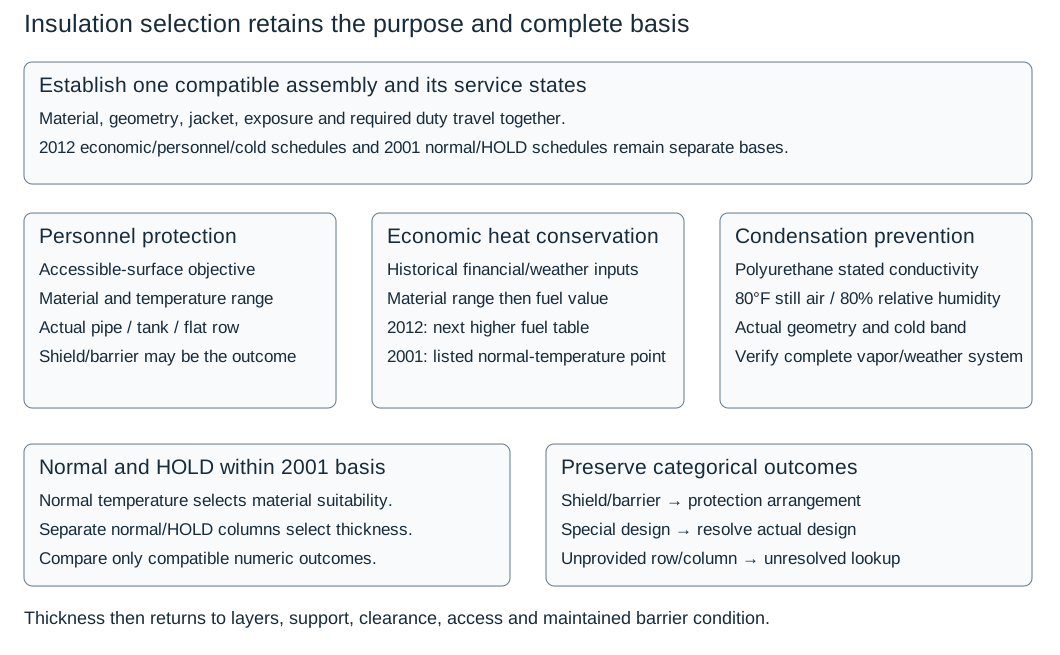
Figure 15.1. A schedule lookup carries one basis, duty, material, geometry and temperature meaning into its outcome. The comparison of compatible normal and HOLD selections remains within the same assembly. Mechanical protection and special design are distinct actions, not thickness values. Complete schedule library and applicability records.
Materials, jackets and supports
Select products for normal and abnormal exposure, including steamout, cleaning and flushing. Adhesives, sealers and polymeric layers need suitability at their actual position and temperature. A cold composite’s polymeric layer is not automatically suitable at a hot pipe face.
At or below grade, a specified route uses cellular glass where ground moisture precludes wicking material; retain its temperature range and any thermal-shock cushion. Fibrous material can be unsuitable where a particular leaking product is likely to soak it. Insulation and insulating cement for stainless steel can require certification for stress-corrosion-promoting contaminants. Coatings, adhesives, mastics and sealants follow pipe material and temperature.
One jacket basis uses corrugated aluminum with a factory moisture barrier for ordinary duty and stainless steel for special protection. Another requires stainless steel in specified fireproofing, low-melting-alloy, critical-wiring and high-abuse applications, permitting aluminum elsewhere. Retain selected thickness, overlaps and fasteners. Hot sliding laps and cold sealed-barrier details are not interchangeable.
Insulation bands, rings, clips and studs hold the covering; pipe supports carry separate pipe/fluid loads. Continuous insulation at a support can require a specified load-bearing insulation and reinforcement system. Other hot-pipe details use shoes or local small-pipe cutbacks, with different heat-loss and corrosion interfaces.
Measure route clearance from the complete jacketed envelope, including acoustic layers and removable covers. Support and movement details accommodate pipe/equipment motion and insulation expansion, shrinkage or resilience without breaking cold vapor seals or displacing hot weather laps.
Select securement for the layer and the diameter it actually surrounds
Wire and bands retain insulation or jacket. Their diameter input is not automatically nominal pipe size. A February 2001 revision-8 hot-pipe wire schedule uses insulated outside diameter. It applies to the inner layer or a single layer with insulation thickness below 3 inches. Its rows specify:
- 18-gauge wire below 12-inch insulated OD
- 16-gauge wire from 12 through 24 inches
- 0.020-inch-thick by 1/2-inch-wide bands over 24 inches for single and outer layers
Each row uses 9-inch spacing. Preserve the stated layer scope and diameter wording instead of treating this as a wire gauge selected from NPS. Wire-loop ends are twisted, bent over and pushed into the insulation to remove projections. Multiple layers are separately secured.
The complete securement schedules also distinguish vessel orientation and temperature range. For the 70–600°F vessel method, vertical items use 12-inch band spacing and horizontal items 9-inch spacing. Band width is 1/2 inch for vessel OD 6 ft and below and 3/4 inch above 6 ft, with 0.020-inch thickness in either case. The 601–1200°F vessel method uses 9-inch spacing for both its inner and outer/single layers, with the same diameter-dependent widths and thickness.
Each layer is banded separately, tightened by a mechanical tool and secured with the specified stainless wing seals. Additional tightening by kinking is excluded in the higher-temperature route. These temperature-band methods do not establish a blanket insulation-material rating.
In the 70–600°F method, high-fire-risk installations whose covering serves as fireproofing hold both layers with 1/2-inch bands at 9-inch centers and exclude wire. That function-specific construction remains separate from an ordinary retention schedule. Anchor or bridle bands for head bands are 3/4 inch × 0.020 inch under the selected vessel methods. Where multiple bridle bands are used, head connections are staggered. These attachments carry the specified insulation/head arrangement, not the vessel contents or pipe weight.
The spring schedule adds movement take-up for bands on single/outer insulation layers and jacket weather finishes. It uses the vessel's uninsulated OD, temperature range, and a matched 4-inch Type 300-series stainless-steel spring assembly or an approved equivalent under that method. Its maximum initial applied extension is 1/2 inch per spring. Its count basis allows up to 2 inches of secondary extension after heating. More than one spring per band is equally spaced around the insulated item.
The initial extension and subsequent hot extension describe different states. The count is not a spring-rate, stress or fatigue calculation.
The guarded securement method preserves the complete printed count grid. Dashes and smaller diameters have the specific “no springs required” disposition in this route. They do not have a generic missing-data meaning imported from the electric HOLD matrix. The count grid's temperature rows are printed 600–800°F, 801–1000°F and 1000–1200°F, creating a shared 1000°F boundary. Its diameter bands likewise have explicitly printed endpoints, with a first isolated 2-ft-6-inch column and subsequent ranges beginning at 2-ft-7-inch, 3-ft-1-inch and other stated increments.
A value in a fractional gap or at the shared temperature boundary does not have a uniquely supplied lookup. Before application, resolve that exact boundary.
For a conditional example, assume uninsulated vessel OD of 12 ft and temperature 900°F. The 10-ft-1-inch to 15-ft band and 801–1000°F row give three springs per band. A 28-inch OD under the same temperature condition belongs to the smaller-diameter disposition, so this route requires none. The 12-ft result does not demonstrate that three arbitrary current springs can accommodate a vessel's actual movement. Match the specified component, preload, hot-extension basis, band/layer duty, actual temperatures and attachment before installation.
Keep insulation support, jacket restraint and equipment support distinct
A vertical insulation course needs a load path to its selected collar, ring, clip or support angle. The weather jacket can need its own first-course support and a limit on accumulated motion. The pipe or vessel itself retains its separately designed structural support. A ring drawn around the covering therefore does not establish support for pressure contents or equipment weight.
One vertical hot-pipe collar detail applies to insulation at least 1-1/2 inches thick and vertical lines longer than 20 ft. It places the support at least 3 inches above the weld line and requires compatible metallurgy. Its insulation supports must not be welded to alloy lines. A separate skirt-supported vertical-vessel construction excludes stainless-steel vessels and uses compatible rods/nuts, bottom-head insulation securement, expansion material and a support for the jacket. It treats skirt-interior fireproofing only where the vessel drawings specify it. These are different equipment and attachment conditions, not a combined general welded collar.
The vertical-vessel clip/angle alternatives distinguish five functions. A segmented support angle carries an insulation course through its clips. A jacket-motion restraint adds a flat at selected elevations where shell expansion between supports approaches 1-1/2 inches. Under the local detail, it limits jacket travel to that amount. A first-course jacket support adds short peripheral angles.
A partial-fireproofing flashing detail is used where the covering stops below full vessel height and is excluded on vessels subject to thermal expansion. A thin-cover support applies where insulation is 1 inch thick.
The structured A–E function and condition comparison preserves all eight associated construction notes. These include nozzle/weld clearances, clip/angle segmentation, skirt layer support, metallurgy and the diameter condition for top-ring banding slots.
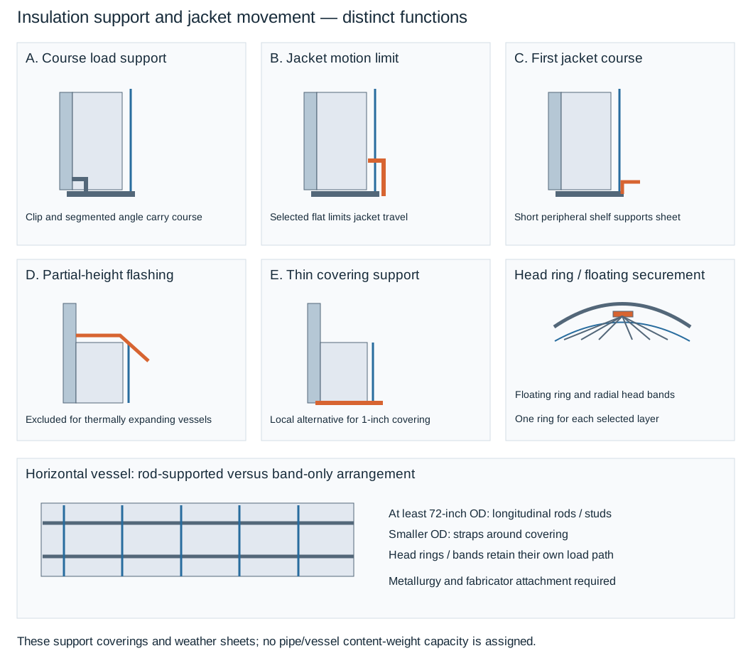
Figure 15.2. A vertical section separates course support, jacket-motion limitation, first-course support, partial-height flashing and thin-cover support. A horizontal/head comparison separates a floating ring and head bands from a rod-supported shell arrangement. Profiles are schematic. The component table and condition record supply their own local dimensions without rating load or movement capacity. Complete construction data.
A vertical-vessel head can use a floating ring for each insulation layer. Bands connect the head covering to the ring, with separate shell support angles. Its local normal-thermal construction places support angles at 12-ft-1-inch band-to-band spacing and packs the expansion joint with mineral wool compatible with operating temperature. A particular fireproofing-only detail omits those selected support angles and expansion joints. That omission belongs to this specific detail and duty. It does not authorize removing hardware from another qualified fire-protection assembly.
For a horizontal vessel at least 72 inches in OD, the selected arrangement uses compatible longitudinal rods supported by studs on both sides. It includes end circumferential rings and head floating rings. Band straps fasten to the longitudinal rods. The end head securement has its own ring/band path.
For smaller vessels, its alternative wraps bands around the insulation and does not require the longitudinal rods and circumferential support rings. Preserve the 72-inch threshold and actual metallurgy/fabricator attachment basis. Similar-looking rods or bands do not prove an authorized pressure-boundary intervention.
The local drawing uses 3/4-inch straps at 9-inch centers on the larger rod-supported arrangement. It uses 1/2-inch straps at 9-inch centers on the smaller alternative. These remain distinct from other vessel-orientation schedules.
A weather boundary has to survive movement and removal
Hot-weather construction arranges overlaps to shed water and protects terminations around an exposed nozzle or manway. At an uninsulated penetration, metal flashing and its selected reinforced mastic join the jacket to the nozzle surface. At a head-to-shell junction:
- Where necessary, pack a void to establish a firm surface for the selected cover.
- Then form the standing seam or the specified lock-seam alternative.
These operations address the actual discontinuity. Adding a jacket without closing the penetration still leaves a path into the covering.
A vertical jacket uses the selected sliding laps, clips and expansion-joint arrangement. Its 2-inch minimum overlap and first-course support do not make the jacket a rigid tie between moving parts. The broader construction uses jacket fasteners on maximum 6-inch vertical-seam and 9-inch horizontal-seam centers where permitted. In cold service, screws and rivets are excluded on smooth or 3/16-inch-corrugated jacketing. For 1-1/4-inch-deep corrugation, the specified fastening exception places them on the high point.
A hot water-shedding lap is not a completed cold vapor seal. Preserve the actual material, fastening and sealed-barrier arrangement for the service.
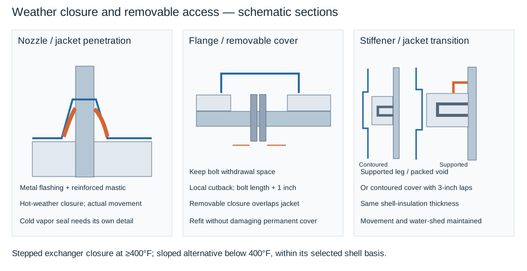
Figure 15.3. The penetration inset separates flashing and mastic from the nozzle. The cover inset preserves a withdrawal space and removable closure. The stiffener inset distinguishes a supported, packed void from a contoured transition. The selected weather/movement detail is restored after removal. Native construction conditions and tables.
For the selected hot valve/flange and tubular-exchanger details:
- Stop permanent insulation short of the flange by the bolt length plus 1 inch to allow removal.
- Retain the specified cover overlap on adjacent jacketed insulation.
This is a local withdrawal-space rule, not a universal minimum for every bolting arrangement. A removable valve enclosure retains its insulation rings, nonflammable high-temperature adhesive, fill insulation and flexible heat-resistant bonnet seal as applicable. Formed pipe/elbow covers and gore segments keep their water-shedding laps and staggered insulation joints. This particular drawing set does not supply a tee-cover specimen to copy.
For the tubular-exchanger closure, the stepped insulated end closure is preferred and required at shell temperatures of 400°F and higher. The sloped alternative is accepted below 400°F under that detail. Its channel and channel-cover insulation is installed only where specified. Preserve the local closure's mesh reinforcement, weather jacket and removable cover conditions rather than treating either drawn outline as a generic temperature rating. A manway-cover attachment that specifies studs installed before heat treatment cannot authorize field welding onto an existing vessel without its own qualified and authorized basis.
At a stiffener ring, one construction uses the vessel fabricator's insulation-support leg and fills the void behind the projecting ring. Another contours the covering around the ring and keeps the specified 3-inch laps above and below. Both retain shell-equivalent insulation thickness, securement and a water-shedding transition, but their physical support and void arrangements differ. After maintenance, restore the selected cover, seam, flashing, overlap and movement provision. Inspect dry material, accessible bolts and names/markings, coating repairs and sealed interfaces before concealment. A restored outline alone does not establish thermal, fire or corrosion performance.
Removable-cover layer limits
Evaluate inner liner, intermediate insulation and outer fabric or metal face at their respective temperatures, including steamout or cleaning. Retain specified seams, fastening and removal arrangement.
One selected cover limits outer fabric to 500°F but requires a cold-face temperature of 110°F. The former is a material limit; the latter an accessible-face target. Neither permits that fabric to contact a hotter pipe. Use the selected heat-transfer assessment rather than assuming a linear temperature drop.
Layer changes must preserve packing-gland access, stud withdrawal, instrument clearance, drainage, leak observation and refitting. Cover-function comparison.
Personnel protection without defeating the process or inspection
Personnel protection begins with accessible surface temperature and the operating or maintenance activity. A guard or shield keeps contact away from a hot item. Insulation changes heat transfer and its surface condition. The choice must protect the person while preserving the item's necessary heat rejection, bolting condition, operation and inspection access.
One adopted protection route applies to surfaces above 140°F reachable from normal work areas, walkways and platforms. Its stated limits are less than 7 ft overhead or less than 3 ft horizontally. It also applies to other readily touched surfaces. For new work between 140°F and 350°F it excludes ordinary personnel-protection insulation except specified high-alloy surfaces not susceptible to corrosion under insulation. Fabricated shields or an approved insulating-coating system are its alternatives. This is a local protection/corrosion choice, not a universal regulatory temperature or reach distance.
Above 350°F that route normally uses insulation. Flanges above 500°F use fabricated shields for personnel protection. Its hot-flange insulation restriction leaves bolts exposed to atmospheric cooling to reduce the potential for flange leakage. The thermal duty, flange bolting and contact-protection arrangements therefore have to be considered together. A removable cover does not automatically resolve an exception that requires exposed bolts at temperature.
The same basis treats normally cool lines that are heated during maintenance steamout differently. Their temporary protection can use restricted access, barriers, procedures and the prescribed work protection instead of permanently installing the normal-operation shield. That state is planned, not ignored because the normal fluid is cool. A separate equipment duty can require heat dissipation—for example from a condensate knockout drum—and use a guard or railing rather than thermal insulation. Access and operating positions and maintenance work connect these choices to actual exposure.
Removable protection is especially useful when access is frequent, but it must be inspectable and refittable. A cover that prevents packing adjustment or removal of studs has traded a maintenance function for an incomplete thermal one. Where leak monitoring requires periodic flange access, the selected removable arrangement should allow it without repeatedly damaging adjacent insulation. The accepted cover material, fasteners and sealing define what is restored after that work.
Ventilated shield stand-off
Expanded or perforated metal permits ventilation, drainage, visual inspection and necessary heat rejection. The adopted shield method requires at least 2.5 inches stand-off and calculation or testing to establish a maximum shield temperature of 140°F. Longer pins can be needed. Preserve operating, inspection and removal space around valves, flanges and instruments. Attachment metallurgy and pressure-boundary work follow the qualified method below.
A personnel schedule selects protection within its assembly
Personnel-protection thickness follows the surface-temperature objective and the selected material/construction. The July 2012 revision-5 schedule basis uses 100°F still air and a maximum accessible surface temperature of 140°F. It provides separate calcium-silicate and mineral-wool schedules for the printed pipe sizes from 1 through 30 inches, vessels and flat work, and storage tanks. The calcium-silicate pipe/equipment bands extend through 1100–1200°F. The mineral-wool bands stop at 800–900°F.
Their separate tank bands stop at 351–400°F. A vessel or flat-work row and a tank row are distinct geometric selections even when their listed thicknesses happen to agree.
The complete personnel-protection schedules preserve each temperature band and row. A “mechanical shield or barrier” outcome for 350°F and below means that this protection route calls for that physical separation instead of an insulation thickness. It is not a zero-thickness thermal entry. This schedule also remains subject to the material/corrosion exception and protection arrangement described above. Finding a numeric cell does not remove the applicable restriction on insulating a reachable surface. The same assembly's heat-conservation requirement can govern where both duties are actually applicable.
For a conditional teaching lookup, assume a 10-inch nominal pipe at 550°F. The 500–599°F personnel band gives 2 inches of calcium silicate and 2 inches of mineral wool. At 300°F it instead returns the mechanical shield/barrier outcome. Thus a temperature change can change the protection mechanism, not only the purchased thickness.
At 1050°F the calcium-silicate pipe row lists 4.5 inches. The mineral-wool schedule supplies no such temperature branch. The absence cannot be filled by extending its final row or choosing a larger mineral-wool thickness by analogy.
A separate August 2001 revision-10 personnel basis uses an aluminum or stainless-steel jacket and a 60°C (140°F) maximum surface temperature. Its stated material maxima are 454°C (850°F) for mineral fiber and 649°C (1200°F) for calcium silicate. Its size/temperature grid includes NPS 1½ and 36 and flat work. Before reading that shared grid, select the material limit. The existence of a 1200°F column does not extend mineral fiber's 850°F material range. Its different exposure/reach and construction requirements remain its own basis.
The schedules provide conditional assembly selections. Verify the installed accessible surface, gaps, supports, jacket and maintained condition against the required protection duty.
A shield needs attachment, safe edges and removable access
The July 2012 revision-5 shield method prefers flattened expanded metal because it preserves visibility, drainage, drying and air circulation. Perforated plate is an alternative subject to that method's approval route. The selected expanded-metal descriptions are 1/2-inch .051 style aluminum and 1/2-inch No. 18 style stainless steel. The perforated alternative uses 1/2-inch holes with 0.063-inch aluminum plate or 20-gauge stainless steel. Stainless shields are reserved particularly for corrosive atmospheres under this method.
Selecting an open sheet also retains the stated stand-off and the required thermal calculation or test. The openness of a shield does not establish its accessible-surface temperature.
For the pin-supported construction, the selected pins are 1/4 inch in diameter, at least 2.5 inches long and threaded at one end. Longer pins can be needed to achieve the 140°F shield-surface target. A stainless-steel nut spot-welded to a stainless disc connects the pin to the sheet support. The disc is 1-1/2 inches in diameter and 1/8 inch thick. A 1/8-inch hex-head stitching screw with an oversized washer secures the shield to the disc.
Complete coating after pin attachment where possible; otherwise repair every attachment before shield installation under the applicable coating system.
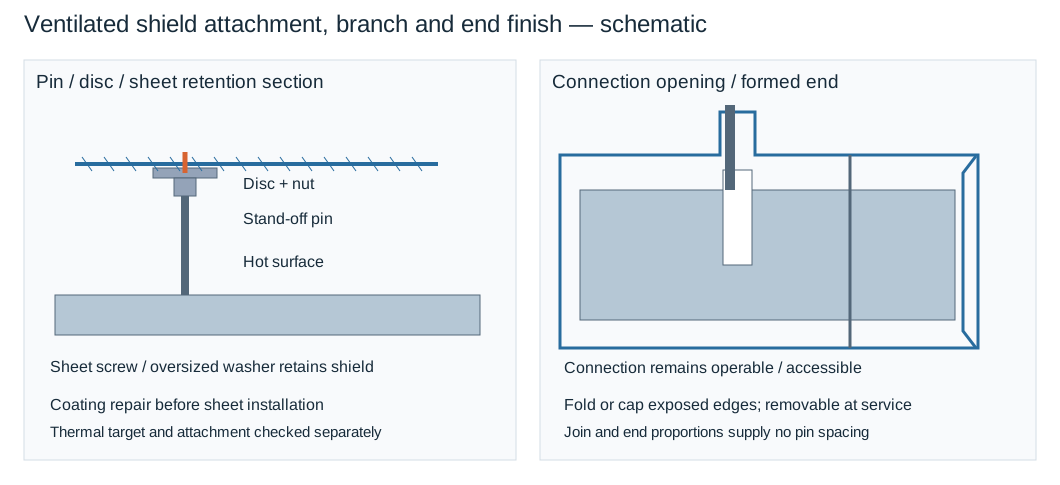
Figure 15.4. The attachment section separates hot surface, stand-off pin, disc/nut and removable sheet fastener. The branch and end insets preserve an opening for connection access and a formed termination without an exposed sharp edge. Shapes are schematic. Pin soundness, spacing and surface temperature require their actual checks. Structured construction conditions.
Approximate longitudinal pin spacing on pipe is 18–24 inches in this construction. For nominal pipe sizes up to and including 6 inches, it uses at least four circumferential pins equally spaced. Larger pipe uses approximately eight, with additional pins considered where support requires them. Other equipment needs adequate sheet support with spacing no greater than 24 inches in any direction. These are the local method's layout conditions, supplemented by additional supports as needed. They do not define a universal sheet-support capacity.
To terminate a pipe shield near a flange:
- Use its formed metal end cap.
- Secure the cap with an insulation band and stitching screws through band and cap.
Where an end cap is impractical, such as at a vessel, fold the sheet edge inward to avoid a sharp exposed edge. Branch openings and sheet joins must preserve ventilation, safe edges, operation and inspection. Flanges, valves and instruments needing service or removal use easily removable shields or barriers with sufficient stand-off for that access. For hot flanges above 500°F that remain uninsulated to preserve bolt cooling, use the specifically selected flange-shield arrangement. A generic close-fitting insulating cover changes that duty.
The attachment procedure remains separate from the sheet geometry. This method requires capacitor-discharge stud attachment to minimize heat input and penetration. Other arc processes need its explicit approved procedure.
For code piping/equipment, including items subject to postweld heat treatment, the selected capacitor-discharge procedure is qualified to ASME Section IX QW-192. Its stated route without subsequent PWHT remains conditional on that qualified procedure and authorized work basis, rather than a generic waiver. In-service and retrofit attachment also retain the required work authorization and in-service welding provisions.
Stainless pins apply to carbon-steel, low-alloy and stainless piping under this method. High-alloy piping requires its approved pin material. Confirm metallurgy, pressure-boundary intervention and coating restoration before attachment.
Heating-jacket connections and drainage
A process-fluid heating jacket is a separate pressure-containing space around the core pipe; it can itself require insulation and weather jacketing. Under the selected metallic core-and-jacket method:
- Liquid medium: supply at the lowest inlet tapping and discharge at the highest point. Check intervening high points for retained gas and the annular path for bypassed heating surfaces.
- Condensing vapor: supply at the highest jacket tapping; drain condensate from the lowest pipe or fitting. A common return header is permitted. Provide effective noncondensable-gas clearing as well as liquid drainage.
The same basis requires countercurrent heating-medium/product flow. It recommends 1% installed slope and no more than eight jacketed pipe sections, valves or fittings per circuit. The count is not a length limit or capacity rating. A 1% slope over an illustrative 6.0 m horizontal run gives 0.060 m (60 mm) fall; fittings and return pressure can still prevent drainage. Connection conditions and slope example.
Changed medium, connections, return condition or jacket termination can change thermal duty. Retain core/jacket mechanical interaction and separate test boundaries as separate design checks.
Steam-tracer type and service
Select tracer type with heat duty, product overheating sensitivity, steam condition, heated length and drainage. The insulation bore and fitting sections must enclose actual tube, connections and attachments.
Bare convection tracing can serve modest freeze-protection or maintenance duty when one circuit supplies enough heat. Isolated tracing reduces local contact heating for sensitive products, including specified aqueous chemicals, resins or amines. Compound-assisted tracing supplies higher heat density, more uniform heating or faster recovery where the product permits it. Multiple convection circuits add supply and trap assemblies; one suitable compound-assisted circuit can be preferable.
Hold bare convection tubing against metal without compound. For isolated tracing, keep the specified isolating medium between tube and pipe when securing the tube.
Preinsulated tubing is another isolated arrangement: retain its insulation and secure it with high-temperature tape. Select delivery data for the actual contact construction, not tube OD alone.
For conductive tracing, compound creates a broader path from tracer to pipe. One detail spreads heat-transfer cement over a width of 2D to 3D, with D identified as the tracer diameter. Separate constructions retain cement and tube within a channel, or use preformed cement with a channel. Select the compound formulation and channel system for:
- Minimum and maximum normal and abnormal exposure temperatures
- Installation ambient
- Pipe/equipment size and configuration
- Required startup curing
- Solubility resistance and installed cost
Preserve the actual surface preparation, tube position, compound continuity and retention before insulation hides them.

Figure 15.5. Six distinct contact constructions shown as schematic local sections: bare, spacer-isolated, conductive cement, cement/channel, preformed cement/channel and preinsulated isolated tube. Geometry and colors distinguish components. They supply no thermal-performance calculation or fabrication scale. Selectable construction data.
Securement belongs to each construction. The bare example uses stainless wire. The isolated and conductive examples use stainless bands and seals, with a stated band size of 1/2 inch × 0.020 inch. The preinsulated alternative uses high-temperature tape.
These contact details print a maximum interval of 15 inches (450 mm). That pair is retained as printed but is dimensionally inconsistent. 15 inches converts to 381 mm. Do not choose either value as a certified equivalent or repair it silently. Resolve the intended interval in the project detail before fabrication.
A separate straight-pipe banding arrangement specifies tie wires at 24 inches (600 mm) centers. It cannot be combined with the contact-detail interval into one common spacing. The materials, detail and intended contact path determine which securement provision is applicable.
Placement must agree with access and the thermal premise
Circumferential location affects contact, space within the insulation and the route past pipe supports. The illustrated convection arrangements distinguish horizontal and vertical pipe. For horizontal pipe, one tracer is displaced 30° from the bottom radial line. Two tracers are placed 30° to either side of that line. Three tracers use a bottom tracer with the other two 40° to either side. The three-tracer horizontal detail also calls for routing around pipe shoes.
For vertical pipe, the two-tracer illustration uses opposite sides and the three-tracer illustration uses three evenly distributed positions. Its two lower displayed radii are each 30° below the horizontal diameter. The one-tracer vertical view uses a displayed radius 30° from the downward page axis. This is a drawing reference, not a gravity-selected bottom sector of a vertical pipe.
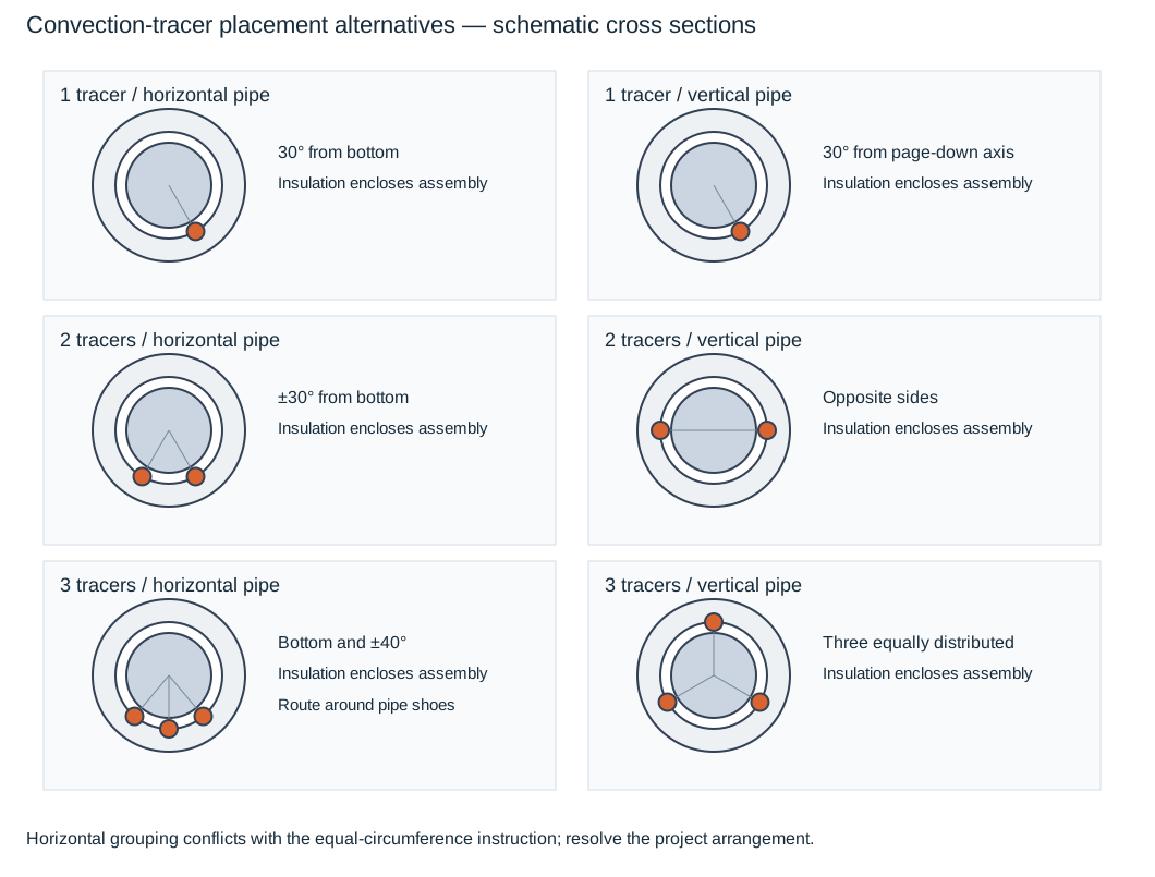
Figure 15.6. Cross sections retain the particular one-, two- and three-tracer placement alternatives. Horizontal lower-sector grouping and vertical distribution are visibly different. Insulation surrounds the completed assembly; tube counts do not establish capacity. Angular references describe these illustrations only. Placement data and constraints.
This construction basis has two incompatible prescriptions for multiple tracers. The installation text requires equal spacing around the circumference. The illustrated arrangements group tracers in the lower sector on horizontal pipe. The latter does not satisfy the former for two or three horizontal tracers. Before installation:
- Keep the selected project arrangement explicit.
- Resolve that disagreement.
Do not rotate the illustration into an apparently reconciled detail or treat the illustrated angles as universal requirements. Retain the accessible surface, support avoidance, ease of connection and the actual insulation bore in that decision.
Tracers generally run parallel to and against the heated item under this basis, subject to the deliberately isolated contact construction. Moving a tube to clear a shoe can alter contact or create a rise. Reevaluate local heating and drainage as well as mechanical clearance. A convenient circumferential location does not prove heat delivery or protection against overheating.
Temperature control likewise has a defined objective. Pipe-wall or ambient sensing, self-acting control or another selected arrangement can serve intermittent operation, energy control, heat-up or shutdown freeze protection. An off/on steam control can be unsuitable for a particularly overheating-sensitive product. Sensor location and response must relate to the part of the system requiring control. A warm location does not establish that a cold dead leg is protected. Sensing and control supplies the measurement consequences.
For size and circuit selection:
- Establish nominal line size, required temperature, ambient and wind basis, insulation system and steam supply condition.
- Compare tracer type, tube size, number and heat-delivery data or the accepted calculation.
- Then verify maximum trapping length and accumulated rise, supply/return lead losses and trap/return conditions.
A circuit that has sufficient nominal heating output can still be too long or poorly drained to deliver it uniformly. Vendor data or a calculation is meaningful only with its applicable geometry and assumptions.
Define the lengths explicitly. The heated tracer length runs from its first contact with the heated line to its connection with the return lead. For a limit defined over the complete circuit, count its applicable supply and return leads as well as the heated length. Long lead runs can require separate pressure-loss evaluation. Do not compare the heated length alone with a limit whose scope includes those leads. The isometric should show manifolds, routing, traps, return and the circuit's identity so that construction and operation use the same configuration.
Carry heat loss into a tracer-delivery comparison
A tracing selection has two different temperature differences. The product loses heat toward the ambient environment, while the steam supplies heat toward the product. Define the differences as follows:
In these equations, is the fluid temperature to be maintained. is the selected ambient temperature, and is the steam temperature used by the heating method. In the customary-unit graphical method developed here, temperatures and their differences are in °F. With fixed steam and ambient temperatures, a higher maintained product temperature increases heat loss and reduces tracer delivery.
The method uses a two-panel chart. The first panel relates nominal pipe size and to heat loss per foot of pipe. The second compares that loss with delivery per foot from a specified tracer at . Both ordinates are in Btu/(h·ft). For a straight parallel tracer serving the same heated run, a foot of tracer corresponds to a foot of pipe.
When comparing the ordinates, keep that length correspondence explicit. Extra tube length at fittings or another routing pattern does not automatically provide uniform extra delivery along the product line. Carrying one ordinate between panels compares quantities on the same heated-length basis. It does not make the two temperature differences interchangeable.
The available loss panel spans –500°F and heat loss up to 400 Btu/(h·ft). The delivery panel spans –350°F. Curves and examples are graphical selection aids, not a validated exact solver or permission to extrapolate beyond their ranges.
Its insulation assumption is 1 inch for nominal pipe sizes 4 inches and smaller, and 1½ inches for sizes 6 inches and larger. The chart does not assign the intervening 5-inch size to a thickness group. More fundamentally, it does not state the insulation material, conductivity or condition needed to transfer its loss curves to an actual installation. Thickness alone cannot establish that transfer.
Use the graphical values as a conditional teaching basis. A real selection needs a compatible thermal-property and installed-envelope basis, or another supported heat-loss calculation. Wet insulation, another material or a different jacket/ambient arrangement cannot simply inherit the plotted loss.
Apply the wind correction to the loss, not to the steam temperature
The chart's loss basis is still air. Its listed winter-wind increments are:
Table 15.2. Listed wind increments for the selected tracing-chart loss basis. Structured wind table and method.
| Wind speed, mph |
Increase in heat loss, % |
| 5 |
7 |
| 10 |
9 |
| 15 |
11 |
| 20 |
12 |
| 25 |
13 |
| 30 |
14 |
For a listed increment expressed as a fraction, the corrected loss is:
In this equation, is the still-air loss, and is the corrected loss. Both are in Btu/(h·ft). This modifies the quantity carried to the delivery panel. It does not change , increase the steam temperature or create a heat-up allowance. The table does not define a rule for unlisted wind speeds or a universal correction independent of its thermal basis.
A graphical reading should retain its precision. If an approximate still-air loss is represented by a reading interval, apply the listed correction to both ends before comparing delivery. A candidate that clears only the lower end is unresolved against that interval. Selecting from an unrounded central estimate can conceal this distinction.
The ordinary-tracer panel identifies outside-diameter tubing of 3/8, 1/2, 3/4 and 1 inch, together with two- and three-tracer 3/4-inch alternatives. It also has separate 3/8- and 1/2-inch curves for heat-transfer cement. The latter represent a changed heat-transfer path. They are not merely larger bare tubes or a multiplier that can be applied to every contact arrangement.
Where several ordinary tracers would be indicated, this selection route calls for considering a compound-assisted alternative, with 3/8- or 1/2-inch tubes recommended for that method. More area can use multiple tubes of those sizes. The actual product must still tolerate the local heat input.
The ordinary delivery panel prints an empirical customary-unit relation:
In these equations, is heat delivery per foot of tracer in Btu/(h·ft). is tracer outside diameter in inches. is outside surface area per foot of tracer in ft²/ft. For a cylindrical tube, the geometric reconstruction is . The coefficient 0.4 belongs to the stated customary-unit correlation, with expressed in Btu/(h·ft²·°F). It is not a dimensionless physical constant that can be reused unchanged with mm and °C.
This reconstruction verifies the printed ordinary-tracer arithmetic. It neither supplies the missing insulation properties nor derives the cement curves, contact resistance, installed capacity or a field acceptance margin.
The chart also lists tubing-to-pipe multipliers. These are 0.862, 0.878, 0.921 and 0.934 beside the respective 3/8-, 1/2-, 3/4- and 1-inch identities. Those printed mappings do not make nominal pipe size equal to tubing outside diameter or establish a general correction formula. Resolve the intended pipe alternative and dimensional basis before using it. The examples here remain explicitly outside-diameter tubing cases.
Follow the indicated selection, then expose the unresolved conditions
A water-line teaching case uses nominal 4-inch pipe, fluid maintained at 35°F and ambient −10°F. Its loss difference is °F. With a stated steam temperature of 250°F, the delivery difference is °F, and the graphical example indicates one 3/8-inch outside-diameter tracer. The associated printed steam premise is 30 psig at 250°F. That pressure/temperature pairing conflicts with the saturated-steam condition assumed for ordinary steam tracing.
Keep the temperature-difference arithmetic separate from an accepted steam state. Neither the calculated 215°F difference nor the indicated tube size repairs the premise. The same winterizing discussion elsewhere uses approximately 75°F as a water-maintenance objective. That is another stated duty, not the 35°F worked-case input.
A second case uses nominal 8-inch pipe, maintained fluid at 125°F, ambient 25°F, and stated steam at 150 psig/365°F. Thus °F and °F. The example indicates one 3/8-inch outside-diameter tracer on the still-air chart. Its plotted traverse is around 45 Btu/(h·ft). For the following sensitivity illustration, retain a deliberately broad approximate reading bracket of 40–50 Btu/(h·ft), rather than publish an exact recovered loss coefficient. This bracket is an authored graphical-reading allowance around the example, not a manufacturer's tolerance or a validated thermal uncertainty distribution.
At a listed wind speed of 15 mph, the 11% correction gives 44.4–55.5 Btu/(h·ft). At ΔT₂ = 240°F, the reconstructed ordinary 3/8-inch delivery is about 47.4 Btu/(h·ft), within that interval. It clears the lower end but not the upper. This information cannot confirm that candidate. The approximately 58.8 Btu/(h·ft) reconstruction for 1/2-inch tubing clears the illustrative upper end and is a candidate for further evaluation under the same compatible basis. It is not a final selection, because insulation applicability, actual steam condition and installed heat transfer remain to be established.
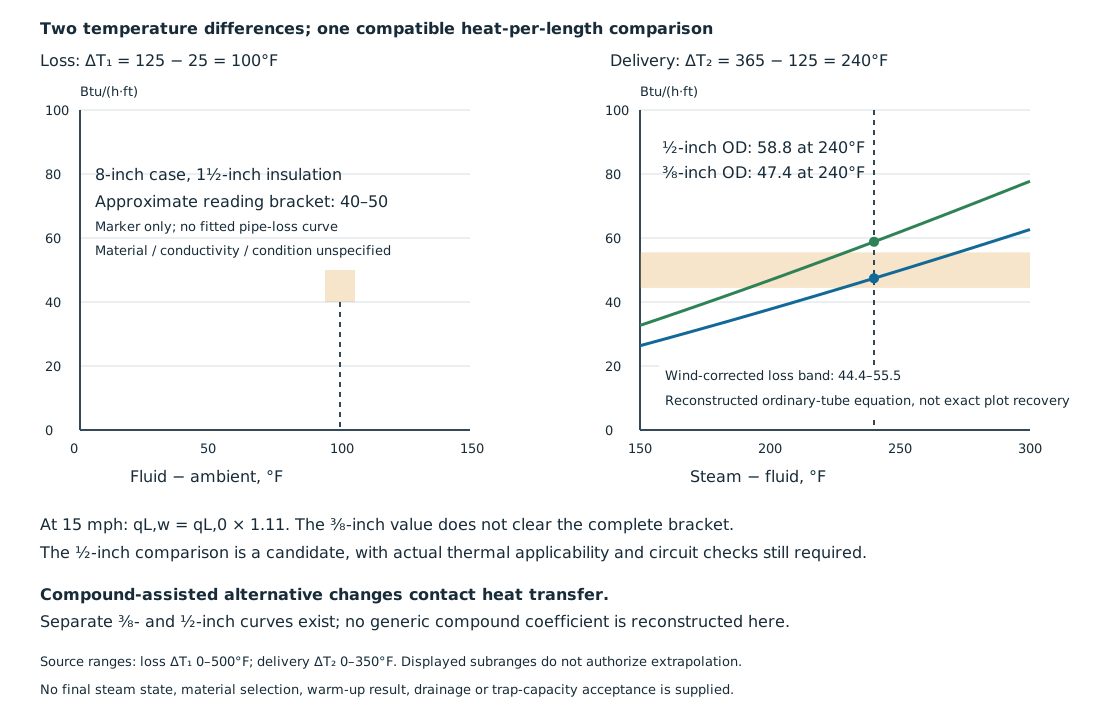
Figure 15.7. A native example view preserves the two temperature differences and the approximate loss bracket for the 8-inch case. The delivery lines are reconstructed from the stated empirical ordinary-tube equation over the displayed subrange. They are not digitized exact source curves. The wind-corrected bracket makes the 3/8-inch comparison unresolved and identifies a 1/2-inch candidate without establishing a real installation. Missing insulation properties remain an applicability limit. Structured method, raw conditions and calculations.
Complete graphical alternatives and limits
The complete curve companion contains loss branches for nominal pipe sizes 1, 1½, 2, 3, 4, 6, 8, 10, 12, 14, 16, 18, 20 and 24 inches. Delivery alternatives are ordinary 3/8-, 1/2-, 3/4- and 1-inch OD tubing; separately plotted two-3/4-inch, two-1-inch and three-3/4-inch arrangements; and separate 3/8- and 1/2-inch compound-assisted traces.
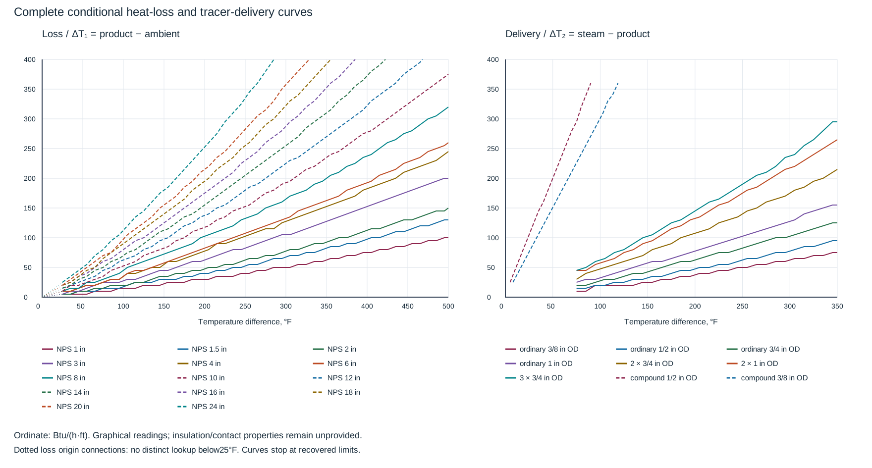
Figure 15.8. Approximate graphical reconstruction. Loss: ΔT₁ 0–500°F; delivery: ΔT₂ 0–350°F; ordinate: 0–400 Btu/(h·ft). Each curve stops at its observed domain or frame intersection. Compound traces occupy only a small part of the delivery axis.
Use these representation limits:
- Readings are rounded to 5 Btu/(h·ft). Working graphical allowances are ±5 Btu/(h·ft) for loss and ordinary delivery, and ±10 for compound and multiple-tracer branches. These are reading allowances, not manufacturing tolerances or installed accuracy.
- Loss and ordinary/multiple delivery are sampled at 10°F intervals; compound traces at 5°F. Display representatives preserve inspected monotonic shape within those allowances; raw rounded readings remain in the data.
- Separately recovered terminal readings reach the right axis, 400-Btu/(h·ft) ceiling or visible compound termination near 360 Btu/(h·ft). Upper-frame and compound terminal abscissas have a working ±3°F allowance. Do not continue curves across blank space.
- Closely merged loss traces have no distinct numerical lookup below 25°F; the zero origin is separate. A delivery/loss separation smaller than the graphical allowance cannot reliably distinguish candidates.
Read loss at ΔT₁, apply the listed wind increment, and compare the resulting range with the selected delivery branch at ΔT₂ on the same heated-length basis. Do not substitute arithmetic multiples for separately plotted multiple-tracer curves. The ordinary correlation does not derive compound contact performance. Recommended compound tubes are 3/8 and 1/2 inch under this method; multiple such tubes can add contact area, but lengths follow the selected manufacturer’s recommendation.
The loss basis remains 1-inch insulation for NPS 4 and smaller and 1½-inch insulation for NPS 6 and larger, with no NPS 5 assignment. Material, conductivity, emittance and condition are not provided. Compound formulation, contact coefficient and curing basis are also missing. Results are conditional comparisons, not installed ratings for another assembly.
The printed conversion is W/ft = Btu/(h·ft) × 0.293. Matched tube-to-pipe factors are 0.862 for 3/8-inch OD tubing to 3/8-inch pipe, 0.878 for 1/2 to 1/2, 0.921 for 3/4 to 3/4, and 0.934 for 1 to 1. Apply only those matched sizes on this graphical basis; they do not establish general interchangeability or compound equivalence.
At ΔT₂ = 200°F, neither compound trace provides a lookup, although the value is within the delivery-panel axis.
Thermal indication does not finish the circuit selection
Under this particular route, ordinary tracer sizes range from 3/8 to 1 inch outside diameter. At 15–25 psig, its stated maximum lengths are 200 ft for 3/8- and 1/2-inch tubing and 300 ft for 3/4- and 1-inch tubing. At 50–200 psig, the small-tube limit remains 200 ft while the larger-tube limit is 400 ft.
Pressures above 25 and below 50 psig have no supplied length band. The 30-psig first example therefore cannot obtain a length permission from these rows. Values outside the stated bands remain unprovided. Compound-assisted lengths follow the selected manufacturer's recommendation instead of inheriting an ordinary-tube row.
These rows call the quantity tracer length but do not resolve the treatment of supply and return leads. Before comparing an actual circuit, establish that scope. Do not silently borrow the lead-counting definition of another procedure.
The same route defines pocket depth as an upward rise in the tracer’s flow direction. Total pocket depth is the sum of all such rises. It adopts a numerical maximum of 40% of the tracing steam gauge pressure expressed in feet. At 150 psig, this gives ft.
A hypothetical route with upward rises of 18, 12 and 9 ft has 39 ft total. Intervening descents can make its net elevation change small without changing that total. It satisfies that isolated numerical comparison at 150 psig. It does not prove drainage, delivered pressure or trap capacity.
This empirical pocket rule is separate from another method's rise/pressure limits and from the 0.5 psi/ft trap-discharge lift allowance developed below. Do not merge their percentages or substitute net rise for a sum defined as accumulated rise.
Count the upward route, including the local detours
Accumulated rise follows the tracer in its direction of flow. Count each transition from a local low point to the next high point. A later descent does not cancel the preceding rise.
At a flange the tracer's local detour can contribute several rises, identified here as A, B and C. At a valve, repeated wraps can contribute several occurrences of the same rise X. Along the overall route, rises associated with changes in the piping elevation and with local detours both belong to the count. The difference between the supply and termination elevations is therefore insufficient to describe accumulated rise.
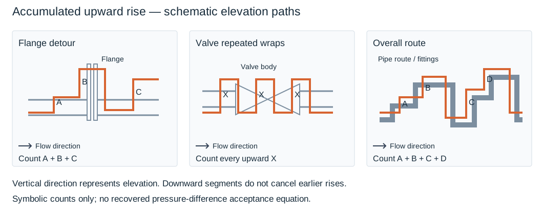
Figure 15.9. Gray pipe, flange and valve outlines relate the orange tracer detours to the hardware in schematic elevation projections. Rise-counting paths identify flange contributions A+B+C, repeated valve contributions ΣX, and the route contributions A+B+C+D. The arrow follows the chosen flow direction. The vertical page direction represents elevation. These symbolic rises have no assumed dimensions. Native counting data.
For any explicitly defined flow path with elevations z at its successive turning points, the counting operation is:
Use one length unit throughout. Elevations in feet give accumulated rise in feet. Elevations in meters give meters. The expression only formalizes adding the identified upward segments. It supplies no pressure-to-rise conversion, rise allowance or drainage acceptance. Include all local high and low points rather than sampling the route so coarsely that a small flange or valve detour disappears.
Three separate numerical bases must remain distinct. The preceding empirical route uses 40% of tracing steam gauge pressure expressed numerically as feet. A separate installation clause limits accumulated vertical rise in feet to 15% of steam supply pressure unless otherwise approved. Its stated wording does not provide a general dimensionally derived pressure/height equation.
The accompanying pressure-difference display contains unresolved operator glyphs around its pressure difference and numerical factor. No scalar acceptance equation is reconstructed from that display. Neither the 40% route nor the 15% clause can be inserted into it as a repair. Establish the applicable resolved design criterion before accepting a circuit against a limit.
Check slope, tracer-inlet pressure, losses and condensate removal separately from accumulated rise. Recount after reversing flow or changing valve wraps and flange detours.
Bring the indicated tube/contact arrangement back to the actual pipe. Check the actual arrangement for:
- Overheated product near a contact tracer
- Cold branches and dead legs
- Sufficient envelope space and accessible joints
- Accumulated circuit loss
- All retained-liquid locations
This route uses insulation spacers where a contacting tracer could overheat specified chemical services. Spacers alter delivery as well as protection. A nominally adequate heat-per-foot comparison does not establish warm-up time, freedom from local overheating, or heat delivery along a long circuit after steam-pressure loss. Steam and condensate service supplies the trap inlet/return-pressure balance and condensate-removal duty. The following drainage account carries those conditions into the tracing route.
Drainage, expansion and the trap discharge condition
Steam supply is selected to remain available during the required states and deliver the design load. A dry saturated supply and appropriately drained header/manifold support that condition. Each tracer's trap removes condensate and air so that heat transfer remains effective. A flooded or air-bound circuit cannot be repaired simply by increasing the insulation thickness.
Size the trap for both cold-start and steady condensate loads at the actual pressure differential; tube diameter or a single advertised capacity is insufficient.
Route supply and tracing from suitable high points downward where possible, avoiding pockets. A default steam-tracing method excludes spiral convection tracers because circumferential expansion can enlarge the gap from the pipe and horizontal pockets impair drainage. Doubling back also has pressure-drop and trapping consequences. Parallel, continuous circuits and their selected slope, branch and termination arrangement should preserve drainage while allowing access at supports and equipment.
Provide tracer movement, disconnection and weather-sealed penetrations using the following separate details.
Movement, disconnection and penetration are separate interfaces
Under the selected bare-tracer construction basis, elbows and flanges absorb tube expansion where possible. Long straight runs instead use 12-inch (0.305-m) diameter horizontal loops at 60–100 ft (18–30 m) intervals, preferably midway between fittings. These dimensions belong to that construction basis; assess actual tube flexibility separately.
The tube still needs its applicable material, pressure/temperature rating, bend radius and route evaluation. Its shaping method uses a mechanical tubing bender and rejects kinks, wrinkles and flattening. It typically uses bend radii of four to ten tube outside diameters, choosing the largest functional radius. A loop sketched without a kink does not prove that a particular formed tube meets those conditions.
The adopted text excludes unions from expansion loops. It separately calls for horizontal flange loops allowing shutdown drainage, with unions where needed to disconnect valves, pumps, tanks or other flange-connected equipment.
The associated expansion illustration depicts a union or elbow option within the expansion loop and therefore conflicts with that union exclusion. The native movement sketch below follows the union-free expansion premise and keeps the accessible removal union in its own panel. An elbow fitting alternative cannot be credited with removal access, flexibility or fatigue performance merely because an illustration offers it. Record a resolved construction choice rather than combining incompatible alternatives.
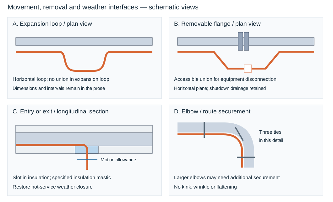
Figure 15.10. The expansion panel is a union-free movement loop. The flange panel has a separate accessible removal union. The penetration panel shows a slot with insulation mastic, and the elbow panel shows securement maintaining the route. Views are schematic and the loop's plane is identified separately. Drawn proportions supply no dimensions. Structured interface constraints.
Form the tube to the union centerline without distortion or tension. To retain removal access:
- Place the removal joint where a maintainer can reach and disconnect it.
- Preserve the flange’s withdrawal space and the removable insulation interface.
The penetration construction shows the tracer carried outside the permanent insulation at the flange. It has insulation mastic at the openings and insulating tape around exposed tube. That arrangement preserves a separable tube connection. It does not justify leaving a hot exposed section unprotected or burying the union where removal damages the permanent covering. The alternative flange securement illustrations use wire or banding at the pipe and, in one arrangement, banding at the flange. Choose the complete compatible detail with its removal geometry.
At a straight-line entry or exit:
- Slot the insulation to accommodate tracer expansion.
- Fill the slot with the specified insulation mastic.
Select mastic, tape and jacket treatment for actual temperature, exposure and movement; preserve tube travel and restore weather closure after servicing. This hot-service slot is not a generic cold vapor seal.
At an elbow, securement follows the curved tube route. One elbow detail shows tie wires at three places, while the separate arrangement note allows additional wire or banding for larger pipe elbows. Neither establishes that every elbow requires exactly three ties regardless of size or curvature. Keep the tracer in its selected thermal relation to the pipe through the bend, with sufficient support and without pinching or flattening.
Under this basis, ordinary hangers, tees and elbows typically do not require extra tracer length. Valves and large equipment do. Supports or flanges in critical service require extra length. Insulated supports are considered for critical temperature maintenance. Carry any added length and local rerouting into the thermal and drainage evaluation rather than treating securement alone as proof of heating.
Each circuit has its specified separate trap station, with isolation and access for servicing. A continuing pipe run beyond the maximum trapping length requires another correctly supplied/trapped circuit rather than an arbitrary extension of the first. A branch, where permitted, needs its own trapping arrangement under that route. Traps and manifolds can also need freeze protection or drainage when shut off. Their operating heating and their shutdown condition are different states.
Lift and backpressure can prevent heat delivery
A trap discharging to an overhead condensate return must overcome return-header pressure and the applicable lift. A particular tracing route prescribes a lift allowance of 0.5 psi per vertical foot. Using that adopted allowance:
In this equation, h is upward discharge lift in feet, and ΔP_lift is the allowance in psi. This is the stated tracing-method allowance, not a universal density-based hydrostatic equation. The available differential also includes the actual pressure at the trap inlet, return pressure and applicable line losses. Gauge pressures can be subtracted when they share the same atmospheric reference. The pressure difference itself is not an absolute pressure.
For hypothetical h = 12 ft and return-header pressure of 8 psig, the allowance adds 6 psi. This gives a 14 psig backpressure estimate before additional discharge losses. If the actual trap-inlet condition is an assumed 22 psig, the remaining difference is 8 psi before those further losses. These figures explain the relation. They do not establish capacity or select a trap.
Its actual capacity and allowed backpressure must fit the operating, startup and shutdown conditions. The plant steam-header pressure alone is not necessarily the pressure reaching the trap.
A return connection and any required check valve follow the accepted discharge geometry and backflow protection. An accessible test point can help verify trap performance. Steam and condensate systems carries the broader supply, trap and return behavior. The tracing design retains the particular circuit and thermal duty. If changes increase lift, return pressure, heated length or lead loss, that connected selection must be reevaluated.
Equipment, instruments and electric tracing
Include dead legs, covers, supports and large fittings where the selected critical-temperature method requires extra tracing. Equipment and pipe circuits can use separate supply/trap arrangements; added tube and lead lengths remain in the applicable trapping assessment.
Cover the irregular surface without obstructing removal
A valve body, bonnet, pump housing or vessel head cannot be represented by the straight pipe's contact line alone. Hairpin tubing distributes contact over that surface while minimizing complete circles in the selected valve/pump method. Its tracer length per unit surface area is required to be at least the corresponding straight-pipe ratio under that basis. The number of hairpins is limited by the usable tube bend radius and accessible surface. Evaluate delivered heat and warm-up for that construction.
The selected valve/pump securement permits 1/2-inch × 0.020-inch (12-mm × 0.5-mm) stainless bands, high-temperature fiberglass tape or No. 16 gauge stainless wire unless otherwise specified. The irregular-surface cross section illustrates adjacent tubular tracers at approximately 3-inch spacing under insulation. That illustrative spacing is not an independent heat-output rule for every housing. To preserve and assess the construction:
- Preserve the contact type through the route, including the selected compound or deliberate isolating medium.
- Assess curvature, pressure/temperature suitability and exposed areas that the tubes cannot reach.
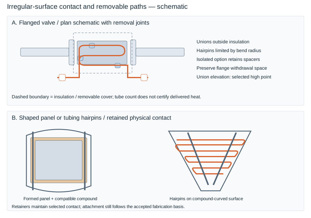
Figure 15.11. A valve/hairpin removal panel in plan schematic shows unions outside the insulation and distinct isolated contact. An equipment panel compares a shaped heating panel with tubing hairpins on an irregular or compound-curved surface. Securement holds the intended contact arrangement while preserving service access. Structured component and dimensional conditions.
The flanged-valve detail distinguishes small and large valves. For NPS 3 and smaller valves, it shows an isolated-tracing option with three insulating spacers. It says 3/8-inch tubing may be used for wrapping NPS 3 valves. The same detail's general bottom note specifies all tubing as 1/2-inch outside diameter. That exception/general-note conflict remains unresolved. Select and document the intended size rather than treating both as one certified instruction.
For NPS 4 and larger valves, the isolated arrangement calls for spacers at two-foot intervals along the tubing. For lines NPS 8 and larger, it calls for two tracers. The second goes around the end flanges and once around the bonnet on bonneted valves. Those additional routes remain subject to actual bend radius, contact, heating duty and removal geometry.
Place the valve's tubing unions outside the insulation and at the high point specified by that detail to reduce condensate accumulation there. This is a local removal/drainage construction and must remain consistent with the complete route. Locating one joint high does not demonstrate that all pockets are absent. A detachable valve or pump tracer connection differs from a dedicated expansion loop that excludes unions.
At a pump, the tube route follows the housing and removable flange connection while banding preserves contact. An elbow-fitting option shown at that connection is not equivalent to a separable union for maintenance. Establish the accessible disconnection actually needed by the assembly.
For vessels, the selected alternatives are prefabricated stainless heating panels formed to the required radius, or hairpin tubing panels. A prefabricated panel can use factory-applied nonhardening compound between its back and the vessel surface. For outside radii of curvature below 7 inches (178 mm), and for vessel bottoms with compound-curved surfaces, tubing hairpins can replace heating panels. Unless otherwise specified, those hairpins are embedded in heat-transfer compound. A rigid panel forced against an incompatible radius can lose the intended contact path. A fitted tube panel still needs its supported compound formulation and securement.
The horizontal-vessel construction illustrates 1/2-inch × 0.020-inch stainless bands and seals, with 24-inch (600-mm) spacing. Its flat-bar retainers are 1/2 inch × 1/4 inch with length as required. The vertical vessel view uses 3/8-inch threaded studs at approximately 24-inch (600-mm) centers with those bars. The cone-bottom arrangement instead calls for 1-1/2-inch × 1/4-inch flat bars, length as required.
Use each retainer with its specified construction, fabrication and material basis; pressure-boundary attachments require their applicable authorization.
Before concealment, check coverage, contact, tube bends and removal access. Reassess surface area, contact and clearances after valve or pump replacement.
Keep the heated sensing path separate from the serviceable instrument
An instrument's process connection, impulse lead, sensing chamber and enclosure can have different thermal duties. Under the selected construction basis, direct tracing is confined to process-wetted parts and excludes electronic and pneumatic parts. Particular enclosures may instead receive indirect heat. A pressure-gauge enclosure receives process-line heat through conservation insulation carried to the enclosure or tracing continued to the gauge connection. A partially enclosed differential-pressure transmitter uses a steam heater block below it. The partially enclosed transmitter assembly has its own flexible insulation cover and clearance for transmitter removal.
A complete polyurethane enclosure can use the specified finned steam heater. Direct process tracing and enclosure heating remain separate selections.
For the selected gauge-glass and external-displacer applications, the tubing size is 1/2-inch (12-mm) outside diameter. Meter leads use 3/8-inch (10-mm) or 1/2-inch (12-mm) outside diameter. These printed pairs identify the particular application choices, not heat outputs or a common bore for every instrument. Determine the actual heat duty, pressure/temperature suitability, contact construction and removal path for the selected package. Preinsulated bundles are an alternative to field-traced and insulated leads where their supported thermal and installation properties fit the duty.
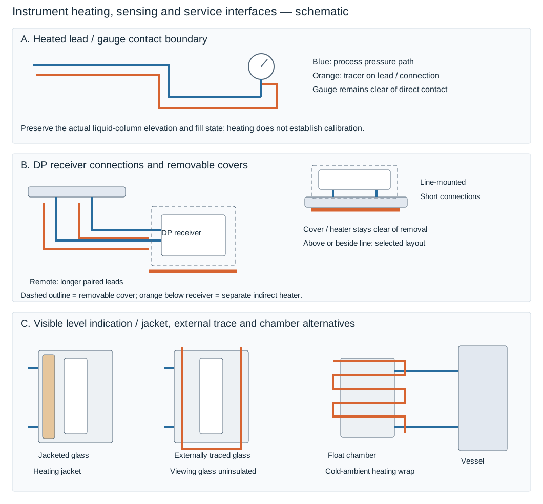
Figure 15.12. Three schematic comparisons retain the physical interfaces. A heated gauge lead keeps the gauge clear of direct tracer contact. Remote and line-mounted differential-pressure sensing retain removable cover heating. Jacketed and externally traced level-glass alternatives preserve the viewing face, alongside the cold-ambient float-chamber wrap alternative. Blue paths carry process pressure, orange paths provide heating and dashed outlines identify removable covers. Structured construction alternatives.
For a remote liquid pressure gauge, trace the lead and its connection while allowing the tracer to contact piping but not the gauge itself. The same contact boundary applies to the illustrated gauge or switch on a traced line. Horizontal and vertical main-line arrangements lead differently to the gauge connection. The liquid/steam pressure-transmitter arrangement can contain a hydrostatic leg between the tapping and transmitter. Preserve that actual elevation and liquid-column state when the thermal treatment is installed.
Remote differential-pressure construction traces and insulates the paired impulse leads together while providing the selected insulating cover around the receiver. Line-mounted alternatives shorten that connection and place the receiver directly by the sensing element, with distinct layouts above or beside the line. A flanged differential-pressure level transmitter and a differential-pressure vessel-level arrangement have their own process connections and removal joints.
Keep those interfaces serviceable. Under this basis, tubing unions and the heater/cover position must allow instrument removal without interrupting or removing the tracing. Retain lead density, zero/elevation offset and reference-path communication in the assessment. Pressure-reference and level-calibration behavior supplies the consequence of the actual fill, density and elevation state. Thermal construction must preserve that state rather than replace its calibration argument.
Level-chamber heating and visibility
A jacketed level glass heats through its jacket; the externally traced alternative routes tubing around the assembly. For the illustrated traced detail, leave the viewing glass uninsulated and retain tubing unions for removal.
The external float-level chamber’s cold-ambient option wraps or coils tubing around the chamber. This equipment detail is separate from the default exclusion of spiral convection tracing on ordinary pipe. Preserve communicating process connections, fluid state, removal access and mechanical response; heating does not establish representative level or calibration.
Check gauge tracer clearance, glass visibility, cover refitting and instrument withdrawal space after servicing. Changed lead length, fill liquid, heater contact or enclosure can change heating and pressure/head interpretation.
Before insulating electric tracing, verify insulation type, bore and thickness against its layout. Protect heater and cold leads from mechanical damage. Do not embed cable in a seam or groove where the prescribed method identifies burnout risk.
An electric-tracing HOLD thickness carries cable and environmental premises
HOLD temperature names the process condition to maintain. It is distinct from the normal operating temperature, the lowest ambient design temperature and the maximum permitted cable/sheath condition. A February 2001 revision-8 electric-tracing optimization basis supplies separate calcium-silicate and mineral-wool matrices. Their HOLD temperatures are 50, 75, 100, 125, 150, 175, 200, 225 and 250°F. Both use an assumed autoignition temperature of 500°F (260°C) and a minimum design temperature of −58°F (−50°C).
The calcium-silicate matrix identifies mineral-insulated cable heat-tracing sheath optimization explicitly. These numerical assumptions belong to that matrix basis. The 500°F value is not an established ignition temperature for every process fluid or an unrestricted operating limit for a cable.
The complete electric HOLD matrices retain all seventeen listed pipe-size rows, from 3/4 through 30 inches, and all nine HOLD columns for each material. Their dashes mean that no thickness selection is provided in that cell. They do not mean zero covering, permission to extrapolate the last numeric thickness, or that the line needs no heating. The conditional retrieval method requires the actual stated HOLD column and the retained environmental/ignition assumptions to agree before returning the stored outcome. It supplies no independently calculated cable-power or sheath-temperature result.
For a conditional comparison at NPS 8 and the listed 175°F HOLD temperature, the calcium-silicate matrix gives 3 inches. The mineral-wool matrix gives 2.5 inches. At NPS 30 and the listed 200°F HOLD temperature, calcium silicate gives a dash while mineral wool lists 4 inches. That distinction is visible data under the respective matrices. It does not establish mineral-wool suitability for an actual installation with a different cable, ignition premise or process duty.
A request for 180°F has no exact listed HOLD column, and a different minimum ambient cannot inherit these values without a supported evaluation. Retain material/product suitability at normal and abnormal exposure temperatures as well as the HOLD duty.
Insulation thickness can be increased when process reasons require it, or when justified for long-term economic and environmental carbon-dioxide-emission reasons under this route. Its general installation rule retains the greater of specified line-designation thickness and the applicable chart thickness. Tracing alone does not authorize changing a specified thickness unless the drawings identify that change. Establish the compatible requirement and actual heater/insulation assessment before applying such a comparison. Evaluate warm-up, local sheath temperature and installed protection separately.
Distinguish the insulation bore from radial thickness and the finished envelope
A cable needs its selected contact, securement and installation space inside the insulation. An August 2001 revision-10 construction basis has a separate oversize provision for electrical tracing outside the steam/skin-effect provision. It uses these stated oversizes:
- 1/2-inch oversize for mineral fiber on NPS 8 and smaller
- No oversize for mineral fiber on NPS 10 and larger
- 1/2 inch for calcium silicate and perlite at all sizes
“None” is the table's oversize outcome. It does not prove that every cable fits beneath an ordinary nominal-size covering. The actual cable, product bore and permitted contact geometry remain necessary inputs. The separate steam/skin-effect provision uses 25 mm (1 inch), or 50 mm (2 inches) for dual-tube skin effect. Those different constructions do not select an electric-cable clearance.
Define the dimensions as follows:
- Dₚ is the actual pipe outside diameter.
- Dᵦ is the selected insulation bore.
- t is radial insulation thickness.
- j is the jacket’s effective radial contribution.
For a circular, concentric teaching geometry:
All terms use the same length unit. Dᵢₙₛ is the bare insulation outside diameter. Dfinished includes the selected jacket contribution. Actual jacket corrugation, overlaps, removable covers and fittings can add local projections beyond that idealized diameter. Cable placement can also produce eccentric or locally shaped construction, so neither a nominal bore nor this circular formula replaces the actual product envelope.
The dimensional example uses nominal NPS 6 with mineral-fiber insulation 3 inches thick and electric tracing. Its text calls the insulation ID “NPS 6 plus 1/2 inch”. Its drawing labels a “1/2-inch tracing gap” and a total OD of 13-5/8 inches. Those labels do not supply one consistent, certified radial/diametral convention.
Using an explicitly selected teaching pipe OD of 6.625 inches, a 0.5-inch diametral addition gives Dᵦ = 7.125 inches and Dᵢₙₛ = 13.125 inches. A 0.5-inch radial gap gives Dᵦ = 7.625 inches and Dᵢₙₛ = 13.625 inches, matching the drawing's stated total. Arithmetic explains that match. It does not establish that the radial interpretation overrides the text or that the drawn total includes a specified jacket thickness.

Figure 15.13. Two conditional interpretations use the same selected 6.625-inch pipe OD and 3-inch radial insulation thickness. Their bore additions differ by convention. Jacket contribution j remains a separately specified input. Schematic cable position and circle proportions supply no clearance or thermal permission. Inputs, raw construction outcomes and calculations.
Resolve the selected product bore and intended oversize convention before ordering or assigning finished-envelope clearance. Preserve the drawing's 13-5/8-inch value as a stated example, rather than silently replacing it with the text-based 13-1/8-inch result. Neither value alone establishes the actual finished jacket OD. Before closure:
- Measure arrangement clearance from the complete selected envelope.
- Check the cable’s permitted temperature, contact and mechanical protection.
Rigid-gap wind blocks and nonrigid reinforcement
A selected revision-2 rigid-insulation detail interrupts the annular axial air path with circumferential E-glass wind blocks at elbows, tees, flanges, skid/module boundaries and 20-linear-foot intervals on straight pipe. Its “1200°F E-glass” description is a local material condition, not a rating for every product, cable or assembly. Preserve cable space and contact without crushing or embedding it.
The corresponding nonrigid-covering detail adds an upper jacket lap from 9 o’clock to 3 o’clock to minimize compression by external pressure. It supplies no rated pressure, stiffness, deflection or verified thermal performance. This reinforcement does not replace a rigid-gap wind block.

Figure 15.14. Alternative rigid and nonrigid constructions; schematic proportions. Local conditions.
Keep insulation dry and weather-protected during installation: under the specified electric-tracing method, the heater cannot dry wet insulation. Correct wet material, damaged sheath and incompatible insulation before concealment. Changed bore, blocking, compression or jacket condition requires reevaluation of heat duty and local cable temperature using the actual heater and insulation product basis.
Acoustic and fire protection
Select acoustic covering for the required frequency-band reduction. Combined systems can put the acoustic layer outside the thermal layer. Retain specified densities, thicknesses, barriers, temperature protection, fasteners and openings. Noise-carrying metal supports/brackets can need treatment; resilient shoes or saddles must also meet mechanical support duties. Removable blankets and covers must restore both acoustic and thermal functions after inspection.
Compare the frequency bands that need reduction
The following example uses one adopted covering method. It uses fibrous glass at 6–8 lb/ft³ or mineral wool at 8–10 lb/ft³, with its specified aluminum or stainless jacket. The listed reduction depends on frequency and thickness. It is not a generic attenuation rate per inch or the sound-transmission rating of a separate barrier material.
Table 15.3. Listed reductions for the selected covering. Native frequency-band data and example.
| Frequency, Hz |
1-inch covering, dB |
2-inch covering, dB |
3-inch covering, dB |
| 125 |
0 |
0 |
0 |
| 250 |
0 |
0 |
1 |
| 500 |
3 |
5 |
8 |
| 1,000 |
12 |
14 |
16 |
| 2,000 |
21 |
23 |
25 |
| 4,000 |
30 |
32 |
34 |
| 8,000 |
35 |
35 |
35 |
Assume a teaching requirement of 8 dB reduction at 500 Hz. The selected 2-inch row supplies 5 dB, while the 3-inch row supplies 8 dB and meets that stated comparison under this covering basis. At 125 Hz all three listed thicknesses give zero reduction. Increasing thickness within these rows therefore does not solve that lower-frequency duty. Another noise-path mechanism or qualified construction is needed.
The assumed target is not an installed exposure limit or proof that a real covering achieves the listed result. Keep the specified material, density, jacket, openings, fastening and support interfaces with the assessment. Keep the comparison on its stated basis:
- Do not interpolate an acoustic value for a 2.5-inch thermal thickness.
- Do not add reductions at different frequencies to obtain a broadband result.
- Do not substitute a barrier’s STC value for this covering data.
After choosing a compatible acoustic/thermal system, recheck its complete envelope, route clearances, removable access and support transmission path.
Fire-case credit follows the qualified assembly
One vessel-protection construction requires at least 4 inches (100 mm nominal in that specification) of calcium silicate in staggered double layers with stainless jacketing. It applies to its identified fireproofing duty. Wiring, actuators, low-melting-alloy equipment and other protected items have their own requirements.
That construction rule does not establish credit in a fire-case relief calculation. One specifically adopted route for insulation credited in an API 521 relief-load calculation requires testing and rating by the manufacturer or an approved independent agency. Its assembly must:
- Function effectively at a minimum 1660°F for at least two hours
- Retain the original shape and insulating value
- Retain most of the covering’s integrity
- Resist dislodgement by high-pressure firefighting streams
Under this same adopted fire-credit route, aluminum jacketing is excluded. Its selected jacket is at least 0.010 inch thick, with a smooth, annealed ASTM A240 Type 304 stainless-steel construction. Type 316 can be used where needed. Bands and other installation hardware are stainless steel to match the jacket material. These material and attachment conditions belong to this route, independently of the preceding four-inch construction example.
Use the qualified complete assembly. This route does not accept existing ordinary calcium-silicate or other insulation on resemblance alone; the exposure is a qualification requirement, not a universal material rating.
Keep the credited locations, installed system and qualification conditions in the relief/protection record and identifiable in the field. Removal, damage, replacement with another material or changed attachment can invalidate the assumed credit while leaving a visually covered surface. The fire-case pressure basis, external protection and recurring integrity must refer to the same installed assembly and its maintained condition.
Installation, inspection and changes
Store insulation dry and undamaged. Establish specified coating, clean/dry/frost-free substrate, tracer attachment and testing before closure. For the steam-tracing route that follows the process-line leak test:
- Complete the process test and required coating; prepare pipe and tracer surfaces and install securement.
- Blow supply and tracer runs clean before connecting trap assemblies.
- Complete circuit connections and the specified steam-pressure leak test or appropriate hydrostatic test. Repair leaks and retest before concealment.
- Apply and cure compound where required; protect exposed water-soluble compound from rain.
- Inspect tracing, then install and inspect insulation and weather protection.
Another approved route retains its own sequence. Testing and readiness connects concealed work to the completed line.
Inspect layer staggering, joints, supports and barriers before covering them. Preserve stud withdrawal, packing adjustment, instrument access and removable-cover interfaces. A flange drain or telltale belongs only to its selected leak-detection detail; it is not a general permission to pierce a cold vapor barrier. Inspection ports and refitting seals must restore thermal, vapor/weather and acoustic functions.
Check completed jacket laps, penetrations, movement allowance and actual pipe-support contact. Changed covering thickness or support interfaces require affected layout and movement checks. Identify supply valve, heated circuit and trap consistently with drawings for isolation and maintenance.
Reassess changed valve surface area/removal geometry, tracer length/contact/trap load, return backpressure, broken barriers, and process temperature or overheating sensitivity. Restore the selected assembly and update integrity, modification and technical records.