Chapter 19 — Examination, pressure testing, cleaning and readiness
Pressure testing establishes a result for its defined boundary and test state. It does not establish correct terminals, freedom from debris or release or removal of shipping and temporary restraints, removal of temporary connections, or restoration of the service arrangement. Internal condition and reinstatement remain separate readiness requirements. The governing code, service and adopted procedures determine the methods and acceptance criteria; joint examination and fabrication and construction supply the preceding joint and installation requirements.
Examine the installation and define the boundary
Installation examination covers line identity, sizes and connections; class conformity of materials, ratings or wall, component types and ends; joint makeup, weld profile, flange alignment and visible condition; and location, slope, supports, guides, anchors, clearances and access. A correctly rated valve can face the wrong way, a pressure-tight instrument connection can reach the wrong sensing point, and a guide can act as an unintended anchor. These configuration errors require separate checks from pressure containment. See measurement and control and support behavior.
The test boundary is the volume and pressure-containing arrangement actually subjected to the test. Its diagram identifies:
- Included lines and equipment, and excluded equipment.
- Isolation points, test blinds and temporary spools.
- Fill and pressure sources, gauges, vents, drains and relief provisions.
It also identifies joints requiring observation and any previously tested assemblies whose valid evidence is being reused. The boundary must agree with the physical configuration.
Including compatible vessels or other equipment can simplify filling and reduce repeated setup. Excluding a lower-rated or sensitive component can permit an appropriate piping test, but creates replacement joints and restoration work. Combining lines with different test requirements may be impossible within one pressure range. Sequential tests, beginning with an appropriate higher-pressure subsystem and then including it in a lower-pressure test, can reduce setup work under an adopted plan. Each configuration still needs its own limits and evidence.
Equipment limits must be obtained from the actual design and manufacturing basis. Testing through rotating machinery is generally unsuitable unless a specifically accepted arrangement establishes the permitted pressure and mechanical consequences. A heat exchanger has a further differential-pressure limit. Pressurizing or depressurizing one side faster than the other can overload a common tubesheet or separating part. This can occur even when neither individual pressure exceeds its own rating. The test and release sequence must preserve that differential limit.
Jacketed piping likewise has two pressure boundaries and a differential-pressure condition on the carrier. Testing a jacket can apply external pressure to an empty inner pipe. Under an adopted procedure that tests carrier and jacket independently, the allowable differential still governs. The inner line may require a controlled balancing pressure during the jacket test.
Filling, holding and releasing those pressures must preserve the designed difference. A pressure rating for the jacket alone does not establish the carrier's external-pressure capability. A completed carrier test does not establish that the jacket has been tested.
Make the test state physically suitable
A liquid-filled line can weigh far more than its operating vapor-filled state. Supports, equipment skirts and the connected structure must sustain this condition. Spring locks, temporary supports and restraints follow the selected installation/test method. They are not inferred from the normal operating arrangement. A locked spring changes load paths and movement, while an unlocked spring can move under added fluid weight. The defined test support state supplies the applicable contact, load and release requirements.
Provide high-point vent paths for filling. A closed high-point pocket can leave compressed gas in a nominal hydrostatic test. Low-point drains and local pockets determine how completely the medium can later be removed. Orifice plates, meters, strainers or other restrictions may have to be removed or replaced temporarily to permit filling, venting, flushing or draining. These changes must remain identifiable for reinstatement.
Sensitive instruments and components need their specified protection. Removing an instrument differs from closing an isolation valve. A valve does not automatically provide the required pressure isolation. The test arrangement must also consider valve seat differential, manufacturer-recommended position, check-valve flow direction and trapped cavities. Instrument takeoff piping up to the root valve and lead lines beyond it can have different test boundaries. Disconnecting the instrument does not establish which adjacent tubing has been included or tested.

Figure 19.1. Authored example: a sensitive component is removed and an approved temporary pressure-containing spool occupies its place. Blinds define the test ends. Fill, drain, vent and gauge points belong to that configuration. Restoration removes the temporary items and remakes the service connections. The sketch does not specify a pressure rating, isolation design or support arrangement.
Test blanks and temporary spools must be suitable for the test pressure, material and joint arrangement. Their rating cannot be assumed from their size or from the adjacent pipe. Temporary items should be marked and recorded so that they can be located after the test. Removed internals and instruments should retain their identities and locations. Replacing the wrong orifice plate or valve internal can alter service function while leaving a pressure-tight line.
Joints requiring observation must remain accessible at the required stage. Concealment rules differ. One adopted test procedure prohibits painting or priming before pressure testing. Another permits a fully painted spool only after its specified weld-layer, examination and non-sensitive-test conditions have been satisfied.
A further procedure has documented painting exceptions but still leaves joints uninsulated for leak examination. Apply the complete chosen route. The coating and insulation sequence belongs in the test plan before access is lost.
Size the temporary plate for its gasket geometry
A test blind carries pressure through a plate supported by the selected flange and gasket arrangement. Its loaded geometry differs from straight pipe wall. A historically used ASME B31.3-based test-plate expression is
In this equation, is required plate thickness. is the gasket inside or pitch diameter specified by the applicable arrangement. is pressure difference carried by the plate. is the stress basis for this method. is its quality factor, and is its additional thickness provision.
Use equal pressure units for and , and equal length units for , and .
Test-side gauge pressure gives the plate pressure difference only when the opposite face is at the same local atmospheric pressure. Otherwise, use the actual pressure difference between faces on a common reference. Nominal pipe size is not a substitute for .
The particular temporary-plate basis sets , and psi. This applies to its specified ASTM A285 Grade C or ASTM A516 Grade 55 plate, using 80% of minimum yield. That is a scoped test provision, not a general service allowable at any temperature.

Figure 19.2. The plate is shown alone to identify the method's diameter and thickness. Actual flanges, gaskets, bolts and support conditions are separate design inputs. The structured method companion retains the geometry and a hypothetical arithmetic example. The sketch supplies no fabrication dimensions.
Identification must keep the temporary duty visible: material, size, permitted test pressure and a test-only designation accompany the plate. The adopted detail can require a projecting handle, distinctive marking and gaskets on both faces to protect the flange surfaces. Its outer diameter follows the selected flange-face arrangement. A pressure-grid entry cannot replace verified geometry, material and thickness. Ambiguous unit annotations or inconsistent entries remain unqualified data until resolved.
After testing, remove the test plate under the restoration plan. Service blinds require their own temperature, corrosion, pressure and code basis. A plate suitable for a short test cannot quietly become a permanent operating boundary because its nominal size fits the flanges.
Determine pressure at the relevant temperature and elevation
Design pressure, component rating, required test pressure and maximum permitted test pressure are distinct quantities. Test-pressure selection depends on the governing basis, included materials and components, test and design temperatures, and applicable limits.
A historically stated hydrostatic method for process piping uses
In this equation, P is internal design gauge pressure. P_T is internal hydrostatic test gauge pressure for the illustrated route with an atmospheric exterior. Both pressures are referenced to the local atmosphere. S is the applicable basic allowable stress at design temperature, and S_T is that value at test temperature.
Pressure and stress quantities use consistent units. S_T/S is dimensionless. This pressure reference follows the system pressure definitions and the atmospheric-exterior internal-pressure route. Absolute pressure must not be substituted into this gauge-based multiplication.
A different exterior pressure condition requires its applicable pressure-difference and test-route limits, including external-pressure and jacket/equipment differential constraints. This atmospheric-exterior gauge formulation does not establish them.
The stated temperature correction applies when design temperature exceeds test temperature. Under this method, the ratio is capped at 6.5. A calculated pressure that would produce hoop stress above the specified minimum yield strength at test temperature is reduced as that basis requires. The governing edition and material stress values must be established before project use. The equation does not provide them.
Other adopted procedures select pressure from a limiting component's maximum allowable working pressure or use class-, material-group- and size-specific rules. They must be applied as their own complete basis rather than combined with the temperature-corrected method into a universal formula.
Static head belongs in both the minimum and maximum checks
In a stationary, connected test liquid, pressure changes with elevation. For the following equation, P_g is gauge pressure at elevation z_g. ρ is test-liquid density in kg/m³, and g is gravitational acceleration in m/s². z_i is the elevation of point i in meters, with elevations positive upward. The relation is
The pressure terms are in pascals for these units.
To express the head term in kPa, divide it by 1,000.
This relation describes static liquid head. It omits dynamic filling/flow losses and assumes the specified density represents the column. Pressure increases below the gauge and decreases above it. A gauge at the bottom can show adequate test pressure while a high point remains below its required minimum. A gauge at the top can hide an excessive low-point pressure.
Each included point supplies a permitted range. Using consistent pressure units, the gauge setting must be at least the largest value of P_min,i − ρg(z_g − z_i). It must be no greater than the smallest value of P_max,i − ρg(z_g − z_i). If the lower bound exceeds the upper bound, the proposed test configuration cannot satisfy all of its pressure constraints. A larger pump setting cannot solve that conflict.
If the bounds conflict, split the boundary, change the approved test arrangement or resolve the applicable limits.
An educational example assumes a top gauge and a lower component 12 m below it. It uses ρ = 1,000 kg/m³ and g = 9.81 m/s². The additional pressure at the component is 117.72 kPa. Assume the top requires at least 900 kPa and the lower component permits at most 1,100 kPa during this test.
On these assumed constraints, the top-gauge setting must lie between 900 and 982.28 kPa. A 1,000 kPa top reading would produce 1,117.72 kPa at the lower component and violate its assumed maximum. This calculation establishes the geometric pressure relationship, not the validity of the hypothetical component limits.
Metal and fluid temperatures are separate inputs. Allow the test fluid and system to reach the required equilibrium before interpreting pressure behavior. Brittle-fracture concerns depend on the applicable material and test condition, not simply a comfortable ambient temperature. A procedure may specify a margin above the highest component minimum design metal temperature or another minimum pressurizing basis. Its numerical temperatures remain local to that material/code route. Source-era boiler and process-piping limits are not interchangeable.
Hydrostatic testing: liquid, weight and observation
Water is often the practical hydrostatic medium because it can fill the boundary and permits examination for visible leakage. Its compatibility, quality, temperature, disposal and complete removal still require attention. Air must be expelled before pressurization, and fluid weight must be included in the support state. A nominal liquid test with a substantial air pocket retains a compressed-gas hazard as well as an incomplete filled configuration.
The test arrangement must permit isolation of the pressure source, the required joint observations and the selected holding period. Minimum holds differ between adopted shop, final-line and other test routes; their timings are not interchangeable.
Thermal change can affect a held liquid test. Expansion of a trapped test liquid can increase pressure, so overpressure protection must remain connected to every relevant test volume. A relief device isolated from the boundary by a closed valve cannot protect that boundary. A pump shutdown also does not remove the possibility of thermal pressure rise after filling. The set pressure and capacity of temporary protection follow the selected test basis and limits.
Medium compatibility reaches more than the pipe wall. Test water, inhibitors, antifreeze and their residues must be compatible with valve trim, seals, linings, process fluids and any sensitive catalyst or equipment. Stainless and nickel alloys can require specified chloride limits and thorough removal of deposits. In a prior high-temperature stainless service, the selected preparation may address sensitization and the damage associated with exposing the material during shutdown. A concentrated-acid service can be harmed by residual water that dilutes the acid. A permitted alternative test liquid or a validated drain/dry route follows its specific service basis.
Different chloride schedules illustrate why medium quality cannot be copied from one general paragraph. A particular piping test procedure limits test-fluid chlorides to 50 ppm for its austenitic stainless and nickel-alloy scope. Another construction account uses a different limit for 300-series stainless. Cleaning procedures can have still different values according to acid, neutral/alkaline or rinse conditions. The liquid's purpose, material and governing procedure determine which criterion applies. The chosen criterion should be supported by a water or solution analysis, not by an assumption that potable water satisfies every sensitive service.
A service may need to be water-free. Effective drying after a permitted hydrostatic test may then be preferable to a more harmful test liquid or a gas test. This does not permit an adopted service-specific exclusion to be ignored. A particular test basis excludes water for instrument air, hydraulic and oil systems, LNG and nitrogen systems.
It has a separately controlled HF-acid exception. The permissible medium is decided within that service and material route. Special cleanliness and hazardous services retains the service acceptance condition.
Pneumatic testing: the compressed-gas condition
Gas reduces the added test-fluid weight and may avoid an incompatible liquid, but a compressed gas can expand and release substantial energy when containment fails. The choice must consider the boundary's volume, pressure, material, failure consequences and ability to protect personnel and neighboring equipment. A preference to avoid drying is not sufficient justification where a feasible liquid test and drying method exist.
The gas-test arrangement requires suitable overpressure protection, gas quality and temperature, an exclusion zone and access for the selected staged-pressurization and leak-observation method. The high-pressure hold can be separate from close inspection at reduced pressure.
Pressure-volume screening criteria need particular care. One adopted procedure states a maximum of 50,000 for pressure in pounds per square foot gauge (psfg) multiplied by volume in ft³. Another test guide triggers detailed hazard analysis above 50,000 ft³·psig. The gauge-pressure units differ by a factor of 144, and a maximum screening limit differs from a trigger for further analysis. These are not the same criterion.
Neither pressure-volume product alone is an exact thermodynamic calculation of released energy or a complete exclusion-zone design.
The test medium can create another hazard. Air introduced into a system that has contained hydrocarbons requires the specified cleaning and purging to avoid an explosive mixture. Nitrogen or another inert gas creates a discharge and personnel-exposure condition that remains part of the test and purge plan. Steam or another condensing medium can create a vacuum as it cools. The equipment must be suitable for the resulting condition, and the procedure must control it. A gas appropriate for service does not automatically make a pressure-test method appropriate.
Material permissions also remain local. Brittle materials and plastics not specified for compressed-gas service are excluded by a stated test guide. A general construction basis excludes pneumatic testing on nonmetallic systems. If hydrostatic testing is impractical, a specific RTR basis permits selected alternatives under its material and code route. Those conditions cannot be resolved by treating all plastics as steel or by converting the RTR option into general permission. The material-specific qualified method, service, temperature and approved alternative govern the actual decision.
Leak detection, sensitive tests and eligible alternatives
A proof or primary leak test and a later commissioning leak check can serve different purposes. A module can be tested before transport and require renewed leak checking after installation because movement or remade joints changes the final arrangement. A sensitive test can also be required in addition to the primary hydrostatic or pneumatic test for a defined service or emissions objective. Its method and acceptance sensitivity must match the leak question.
Bubble testing requires accessible leak paths and the prescribed medium, pressure and observation method. Residual water can interfere with sensitive gas testing, so the boundary must permit the required drying. Helium testing requires a defined tracer concentration, calibration, collection/probe arrangement and leak-rate reference conditions.
A system-average leak criterion also needs its actual denominator. If an adopted method uses total measured joint leakage divided by all inspected joints, those joints and valve-packing locations must be identified. A favorable average cannot conceal a joint that fails its individual criterion. “Zero” under a stated acceptance method is a result relative to that method's observation capability and procedure. It is not proof that leakage is physically impossible at every later condition. Standard-volume leak units also retain their reference basis rather than becoming actual flowing volume without conversion.
Apply both local and aggregate leak criteria
A sensitive method must preserve its test question and eligibility. One guide's post-primary bubble route uses the lesser of 15 psig or 25% of design pressure and requires the dry system needed for effective observation. A separate commissioning procedure uses nitrogen/helium for lethal service (including H₂S) and hydrocarbon systems above Class 300. It has its own pressure limits, required overpressure protection and mixture verification. The first pressure rule does not establish the second procedure's pressure, and a helium rate result does not replace the required primary test.
The adopted system procedure uses 99% nitrogen/1% helium with verified mixture and matching calibration. A component-calibration guideline using 10% helium has a different concentration and purpose. The two calibrations are not interchangeable.
The scoped normal-hydrocarbon acceptance example applies to hydrocarbon systems above Class 300 within that adopted nitrogen/helium procedure. Its individual rate limit is 50 standard ft³/year, and its maximum system average is 40 standard ft³/year. The corresponding rounded metric entries are 1.416 and 1.133 standard m³/year.
For rate measurement, define the standard-volume reference conditions under the measurement procedure.
These rates are not uncorrected actual flowing volumes. The average is combined measured leakage divided by the total number of inspected locations, including the specified flange joints and valve packings. Lethal-service zero entries remain results under that detection procedure, not proof of zero physical leakage in every later state.
The structured criteria companion retains the scoped limits, denominator and hypothetical arithmetic examples. Both individual and system-average conditions apply; averaging cannot conceal a failing joint. The inspected population and changed joints govern the required retest.
Pressure retention is another observation. An existing-piping test route permits a closed valve at the boundary. Under that route, the valve is not assumed leak-tight. Pressure drop and the quantity and time of make-up liquid are recorded.
A steady pressure while fluid is added does not prove no loss. Leakage through that isolating valve, external leakage from a fabricated joint and a later tracer measurement are different paths and acceptance questions. That existing-boundary permission cannot be imported as a general allowable leak in new construction.
An initial service test is available only within its governing service and construction/maintenance conditions. A procedure for new Category D systems is different from a post-maintenance hydrocarbon service-test route limited by toxicity, ventilation, isolation, drainage and prescribed monitoring. The latter is not permission to release a new hazardous system without its required construction test. Likewise, a hydrocarbon purge's selected oxygen endpoint must remain service- and procedure-specific. A project value is not a universal flammability boundary.
Alternative testing is another bounded route. Where neither hydrostatic nor pneumatic testing can be performed under an applicable method, the alternative can require:
- A formal flexibility analysis.
- Complete specified volumetric examination of untested groove welds.
- Penetrant examination of other welds, including attachments.
- A bubble test.
It is not a general reduction to visual examination because a connection is difficult to reach. The applicable code, service and engineering/regulatory disposition determine eligibility and the full required work.
A closure weld has its own prerequisites. Under the closure route described in joint examination, the connected systems, subassemblies or components have already been successfully leak tested. The particular in-process/traveler procedure illustrated there is confined to eligible new construction and excludes tie-ins to previously commissioned systems. In-process observation and final NDE establish that joint's required evidence.
They do not establish eligibility for any arbitrary untestable final weld. Other permitted tie-in or intervention alternatives have their own scope. They do not inherit either a blanket ban or a blanket permission from that closure example.
Identify what remains untested at a final tie-in
An existing-system tie-in alternative can be limited to the final field welds of repairs, modifications or tie-ins whose full hydrotest is impractical. Its components and subassemblies are hydrotested beforehand. The route does not extend to substituting examination for a vessel or exchanger test. A live or hot isolation boundary, unavailable closures or an unsuitable full-water support state explains the difficulty. It does not by itself select the alternative examination.
The adopted schedule can distinguish butt-weld volumetric and in-process examination, fillet/socket surface examination, stainless penetrant and ultrasonic scope for large-bore branches. These assignments depend on its service/material/joint basis. It also requires subsequent initial-service observation with the weld area accessible, so the preceding examinations and startup check supply different warrants.
A particular critical-closure restriction applies when pressure is above 900 psig and temperature is above 600°F. That conjunction is separate from the schedule's severe-service classification and from other code routes. Do not change it to either threshold alone or make it a universal permission below those numbers. The selected governing procedure, previously established proof and actual joint type determine eligibility. The formal-analysis/full-examination/bubble route above is a different complete alternative, and its prerequisites cannot be discarded by borrowing only the convenient part of the tie-in schedule.
Material-specific test behavior
Nonmetallic tests retain their joining, temperature, deformation and timing conditions. HDPE testing can require a different procedure from steel, including a relaxation interval before retest. In a specified composite HDPE/steel boundary, the selected procedure can require the HDPE route for the combined test. A calculation at nominal pressure does not establish that a steel holding/pressure-loss criterion describes that mixed boundary.
Prepared ends, thrust restraint and test connections must remain secure. An HDPE installation method can delay testing until its concrete thrust-reaction blocks have reached the specified age and end restraints are in place. All air is expelled, fluid temperature stabilized and component pressure limits respected. A failed section is repaired and retested under the material-specific relaxation and sequence requirements. These conditions connect joint formation and installation with the current physical test state.
Adhesive or cemented RTR joints must finish their required cure before pressure testing. A specified resin-cure observation is not a substitute for the complete joint-production method. The RTR route also has temperature-dependent pressure, maximum total test duration and relaxation after an interrupted test. Its minimum pressure and maximum component limit are evaluated at every relevant point, with head included. Careful pressure increase and suitable controls avoid overpressure or water hammer. Tightening a leaking flange beyond its material's permitted assembly method is not a valid repair.
Testing the material system differs from merely applying a steel test to a different pipe. The system's joint cure, support/contact behavior, pressure/temperature rating, medium compatibility and time dependence remain visible in the test package. Materials supplies the selected system, and supports supplies its actual contact and load conditions.
Observe HDPE expansion in the selected test sequence
A pressure fall in a liquid-filled HDPE line is not necessarily a leak. Time-dependent expansion of the pipe can increase the water volume needed to restore pressure. Changes in pipe or water temperature add another influence. The useful observation is therefore made in a defined sequence. Makeup added while the pipe is initially expanding is not the same quantity as the measured return-to-pressure amount after a later hold. Applying a steel pressure-decay criterion or adding the two volumes together would change the question being tested.
In the HDPE water-test method developed here, fully cooled fusion joints and a suitable restrained test boundary are prerequisites. Before pressurization, equalize the pipe and test-medium temperatures. The route aims for a common temperature below 38°C (100°F) where possible.
Above that temperature, reduce test pressure under the manufacturer's recommendations. Remove or isolate valves and other components that cannot withstand the required system test pressure.
Clean water is the default medium unless another medium is specified under this method. Fill the section completely and purge trapped air through the high points. The installed-system observation is separate from the trial fusion, procedure and bonder qualification developed in joint qualification.
The selected sequence has three stages:
- Initial expansion: pressurize to the selected test pressure. Then add makeup medium each hour for three hours to return to that pressure.
- Test hold: immediately follow the expansion phase with a two-hour hold. Add no makeup medium during this phase.
- Measured return: at the hold's end, add a measured amount of medium to return the section to test pressure. Compare this final amount with the selected size-and-length allowance. Under this method, an amount not greater than that allowance indicates no leakage by this volume observation.
All joints still require leakage inspection during the pressure test. A low final makeup amount does not excuse a visible leaking joint, an unsuitable component, an unstable temperature or a departure from the required test state. The initial expansion makeup is recorded as part of the sequence. It is not the final comparison quantity.
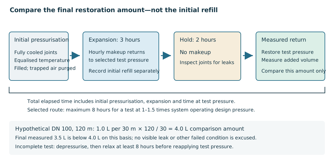
Figure 19.3. Authored state sequence for the selected HDPE test method. The three-hour expansion phase permits hourly makeup; the following two-hour hold does not. Only the measured addition after that hold is compared with the listed allowance. Initial pressurization is included in the method's total-time limit, although it is shown before the timed phases. Structured sequence, quantities and size data supplies the companion representation. The diagram specifies no project test pressure or valve line-up.
Table 19.1. Final test-phase makeup amounts in the selected method, after its two-hour no-makeup hold. The two length/unit columns are the method's rounded published alternatives, not exact conversions of one another. Structured cells and scope.
| Pipe size, DN (NPS) |
Litres per 30 m |
Gallons per 100 ft |
| 80 (3) |
0.5 |
0.15 |
| 100 (4) |
1.0 |
0.25 |
| 150 (6) |
2.3 |
0.60 |
| 200 (8) |
3.8 |
1.0 |
| 250 (10) |
4.9 |
1.3 |
| 300 (12) |
8.7 |
2.3 |
| 350 (14) |
10.6 |
2.8 |
| 400 (16) |
12.5 |
3.3 |
| 450 (18) |
16.3 |
4.3 |
| 500 (20) |
20.8 |
5.5 |
| 600 (24) |
33.7 |
8.9 |
| 750 (30) |
48.1 |
12.7 |
| 900 (36) |
68.1 |
18.0 |
For a homogeneous length evaluated on one column's basis,
Here is the final makeup comparison amount. is the table amount for the selected size and reference length. is the evaluated pipe length. is 30 m or 100 ft for the chosen column.
Use the same length unit for both lengths and retain the selected column's volume unit. This proportional calculation explains the length basis. It does not establish a method for mixed sizes, unlisted components or an altered test configuration.
Select one complete unit/length column; the rounded companion entries do not justify additional precision.
Time limits also belong to this route. For a test at one to one-and-a-half times system operating design pressure, total duration must not exceed eight hours. This duration includes initial pressurization, expansion and time at test pressure. That condition supplies a duration limit. It does not itself select a permissible test pressure for an actual assembly.
If leakage, equipment failure or another interruption prevents completion, depressurize. Before applying test pressure again, allow at least eight hours of relaxation. The three- and two-hour phases do not permit indefinite pressurization before or after them.
Other nonmetallic test guides use different hold periods, temperature guidance or manufacturer-selected pressures. Their conditions cannot be assembled into a hybrid by taking a pressure from one, a holding time from another and this makeup table from a third. The HDPE method used for a specified mixed HDPE/steel boundary, the thrust-block-age requirement mentioned above and an RTR alternative each retain their own eligibility and sequence.
Record the chosen test method, actual temperature, pressure, elapsed times, makeup quantities, length/size basis and leakage observations in the test record. This record lets later retesting use the same physical meaning.
Define cleanliness before selecting the cleaning method
Cleanliness is a required internal condition, not the name of one process. Loose debris can obstruct a burner or damage close-running machinery. Adherent scale can later detach and enter a compressor or oil circuit. Oil, grease, preservatives or cleaning residues can interfere with a sensitive service. A cleaning method is appropriate when it removes the unwanted material without creating an unacceptable new condition in the included materials and equipment.
One useful scoped vocabulary separates four duties:
Table 19.2. Internal-condition duties under the selected cleaning basis.
| Duty |
Required internal condition under this cleaning basis |
| A |
Remove loose non-adherent material and adherent material that could break away in operation |
| B |
Remove oil, grease and protective coatings |
| C |
Remove adherent rust and mill scale to leave bare metal |
| D |
Protect the cleaned surface against rust bloom before startup |
The equipment/material schedule selects the combination and method sequence. Under this particular basis, C and D are performed only when specified by the responsible engineer. The same schedule treats stainless lube/seal-oil piping differently from carbon steel, and its stainless scope includes duplex. These letters are useful locally. They are not universal cleanliness grades or particle-count acceptance categories.
Match the route to the material and equipment boundary
A material-specific machinery-piping procedure chemically cleans ferritic steel to remove dirt, grease, paint, rust and scale down to base metal. It detergent-flushes austenitic stainless steel to remove dirt and grease. Shop cleaning of flanged/threaded work, in-place cleaning where field welds are required and recleaning of equipment-supplied piping have different access and isolation arrangements. Final oil flushing is expressly outside that procedure. The chemically cleaned spool is one input to the later operating oil system.
The following representative routes preserve that distinction beside a broader equipment-cleaning schedule. They describe the selected method family. They do not authorize one route for every installation.
| Bounded route |
Required condition or stage sequence |
Interface that controls the choice |
| Ferritic machinery-piping chemical route |
Flush, degrease, pickle, passivate, dry and protect against rust |
Chemical compatibility and stage observations; bearings/seals excluded; later oil flushing separate |
| Austenitic machinery-piping detergent route |
Remove dirt/grease by degreasing and flushing |
Compatible water/solution and included components; ferritic pickling is not automatically required |
| Carbon-steel lube/seal-oil schedule |
Selected debris/oil/scale/protection duties; water flush, alkaline wash, acid/chelant, passivation and protection |
Bare-metal/protection duties remain conditional where specified by that schedule |
| Stainless lube/seal-oil schedule, including duplex where stated |
Selected debris/oil duties; clean construction, mechanical and compatible solvent cleaning |
This schedule's scope differs from the austenitic detergent route; hydrochloric acid excluded |
| Centrifugal/axial-compressor suction schedule |
Selected debris/oil duties and mechanical cleaning; compatible inhibitor/oil protection or a nitrogen blanket under this route |
Wholly stainless systems are excepted from those preservation measures; temporarily disconnected joints still require blinds, plugs or caps |
| Reciprocating/rotary-compressor suction/interstage schedule |
Listed clean-construction/mechanical or chemical sequences, including connected vessels, exchangers and pulsation devices |
Specific suction chemical-cleaning duty and material exclusions must remain in the selected instructions |
Table 19.3. The structured route comparison retains each scope and its qualifications. Letters A–D above remain local internal-condition duties, rather than universal material cleanliness classes.
A broad matrix can list alternative routes while a specific compressor-suction requirement calls for chemical cleaning. In that case, retain the distinction in the selected instructions.
Neither a table row nor the generic name “cleaning” independently settles the applicable route. Likewise, a stainless base pipe does not establish the material of every valve trim, gasket or instrument in the circulation boundary. The solution must be compatible with every included item, and excluded components must actually be isolated.
A chemical circuit that excludes bearings and seals must retain that bypass. A subsequent manufacturer-defined oil flush can use a different final path through bearings after its initial bypass. Its medium and operating function explain the difference. Combining the two instructions without their boundaries can damage a bearing or leave its operating oil path unverified.
Construction must control weld debris and temporary material before internal access is lost. Mechanical cleaning needs access and debris-removal paths; the chemical route depends on material compatibility and the selected internal-condition duty.
A compressor suction or lube/seal-oil system illustrates the consequence. The required result is not merely a shiny accessible flange. Material that can detach from a hidden pocket must be removed, and the cleaned state preserved through final connection. The extent can include coolers, dampers, bypasses and vessels as specified, while excluding sensitive machinery or internals from a particular cleaning circuit. Burner-fuel lines require unobstructed burner openings after their selected blow/cleaning method. The cleaning diagram should show the actual circulation, bypasses, restrictions, collection points and final acceptance observations.
Flushing flow and the passage it cleans
A fixed circulation flow produces lower mean velocity in a larger bore; parallel branches can receive less flow than the pump discharge total. Use actual internal diameter and flow in each cleaning path. A selected process-system route specifies a minimum 10 ft/s (3.048 m/s). Pump duty, restrictions and the temporary circuit must support the selected route; velocity alone does not establish cleanliness.
Cleaning chemistry, observations and preservation
A chemical-cleaning boundary must be compatible with pipe, valve trim, gaskets, instruments and every included component. A carbon-steel line can contain a stainless instrument or chromium-containing trim. Choosing a cleaner solely from the line's base material can damage that item. Bearings and seals are bypassed in a chemical-cleaning procedure that excludes contact with its cleaning solutions. This is distinct from a final lubricating-oil flush whose equipment-specific method can require flow through bearings after an initial bypass. The medium, phase and equipment instructions distinguish the two routes.
High-point vents and low-point drains are needed to fill, circulate and remove the selected solutions. Acid is not introduced into a boundary lacking its required removal path. Direct heating of an acid-filled item can be excluded by the procedure, which instead heats the diluted solution externally. Degreasing, pickling, rinse, passivation and final examination are separately observed so that completion of one stage does not conceal an unfinished subsequent stage.
The cleaning circuit needs leak-tight temporary connections, high-point vents and drains at low points and blanked-end pockets. Degreasing, oxide removal, rinsing, passivation and drying are distinct stages under a complete material-specific procedure. Required sample/endpoint observations determine completion; individual chemicals or endpoint tests cannot be transferred between routes. Collection and disposal capacity belong to the temporary circuit.
Material restrictions govern chemical selection. Under a stated austenitic-material route, hydrochloric acid and other halide-containing acid cleaners are excluded. Acidic alternatives, neutral/alkaline solutions and rinse water have their respective chloride criteria. Duplex is included where the cleaning schedule says so.
Caustic solutions have their own concentration/residue and flushing concerns. Carbon-steel acid-cleaning appendices describe a different material route and must not be transferred to stainless assemblies. Cleaning penetration and temperature limits likewise belong to the selected procedure.
Completion is established by the required observations and tests, which can include visual and tactile examination, stage-completion checks, filters, screens or specified particle measurements. Visual absence of foreign matter and lack of grittiness can be the selected general condition. A machine-specific lubrication duty can require a finer quantitative criterion. Particle-count classes, screen observations and microscopic-size designations are different methods. Their limits cannot be combined by choosing the smallest displayed number. The manufacturer and service basis establish the method and sampled location.
Keep removal, material loss and moisture criteria distinct
One ferritic/austenitic cleaning basis permits no retained particle larger than 5 mils and limits chemical metal penetration to 0.2 mils. A mil is 0.001 in: the particle length is 0.127 mm (127 μm), while the metal-loss limit is 0.00508 mm (5.08 μm). The first describes remaining debris. The second describes loss of material during cleaning. Neither is a particle-count class or a final machine-oil criterion, and satisfying one does not demonstrate the other. The structured cleaning quantities preserve these different duties and conversions.
Flushing velocity also belongs to a stage. The process-flushing example above uses a 10 ft/s condition. A particular ammoniated-citric-acid circulation/rinse route specifies 2 ft/s. Its chemical concentration, pH, temperature and oxide-removal observations act with that flow condition.
The complete cleaning procedure governs chemistry, stage endpoints and material compatibility. The circulation velocity is a stage condition, not a substitute for the required internal-condition result.
Temperature quantities differ as well. A stainless test-water drying route specifies air below 140°F, while a cleaning restriction limits austenitic equipment metal to 125°F. Gas temperature and attained metal temperature are different observations. A ferritic cleaning route instead uses 160–180°F nitrogen to achieve a stated −40°F dewpoint immediately after draining. Another carbon-steel route uses 150–170°F drying gas.
For drying criteria, retain the selected procedure, material and measured moisture basis with the values. Do not combine the values into one band.
Dewpoint interpretation still requires its measurement pressure/reference and representative location.
The cleaning state can include disassembled, water-filled piping with temporary supports. A particular procedure's 3/8 in deflection limit belongs to that state. It does not replace an operating span's sag criterion. Flow reach, drainability, chemical compatibility and support adequacy must survive the temporary circulation arrangement together.
Preservation closures depend on exposure duration and material. One procedure distinguishes a seven-day erection horizon: specified film at flange ends and line-class plugs for short exposure, secured metal protectors with gaskets and closures for longer exposure. These contamination barriers have no inferred pressure-test rating. Covers remain until permanent connection, with dry attachment/storage and cleaned-state identification.
Compatible rust preventive follows ferritic drying, with excess drained from pockets. In the particular centrifugal/axial-compressor suction route above, compatible vapor-phase inhibitor/rust-preventive protection or a nitrogen blanket are alternatives. Its lubricant-based measure excludes non-lubricated and refrigeration compressors. Under that route, a system constructed entirely of stainless steel does not require those preservation measures.
Temporarily disconnected joints still require blinds, plugs or caps against contamination. That bounded exception does not exempt stainless systems from other selected drying, cleanliness or preservation duties. Changing the exposure period or opening the cleaned joint reopens the preservation decision.
Draining and drying then remove a further contaminant: the cleaning or test medium itself. The fluid can remain in dead legs, low points, instrument connections and cavities. A required dewpoint is a measured moisture condition under its method, not a name for a chosen gas supply. Drying temperatures and gases must be suitable for the material, equipment and service. Cleaned ferritic piping may require compatible rust prevention, while stainless or a non-lubricated compressor can have a different protection duty. Excess preservative in a pocket is itself a condition to remove where required.
Protective covers, plugs, blinds or a prescribed inert blanket preserve the accepted state until final connection. Their duration and integrity affect whether the earlier result remains valid. Opening a cleaned joint, transporting a module, welding a field connection or leaving a system wet can reopen cleanliness or preservation evidence. A final cleaning as close as practicable to first machinery operation can reduce this exposure under the selected equipment route. Special-service cleanliness determines any additional service-specific condition before introduction of the fluid.
Restore the service configuration and demonstrate readiness
Before removing test items or opening joints, depressurize and drain by the prescribed sequence.
Venting prevents trapped pressure and can prevent an unintended vacuum during drainage. Differential-pressure limits remain applicable while releasing connected equipment. The final pressure reading at one gauge does not establish that an isolated pocket is depressurized. Its local boundary and bleed arrangement must be known.
Reinstatement removes test blinds, temporary spools and other items designated for removal. It returns identified instruments and internals to their correct locations. It remakes the affected joints by their assembly method. A restored flange has a new joint-making event even though the adjacent spool passed its earlier test. The required subsequent leak check or examination follows that changed condition. Test records should distinguish the boundary tested from the boundary finally restored.
Restore the defined support state: remove or retain spring locks, shipping ties and temporary supports according to the selected transition; confirm cold settings, contact, guide gaps, movement freedom and expansion-joint preset. Releasing a restraint differs from removing a permanent support. See support states.
Table 19.4. Readiness evidence and changes that reopen it.
| Readiness question |
Evidence to preserve |
Change that can reopen it |
| Is the intended arrangement installed? |
Walkdown, accepted dimensional/configuration changes and component identity |
Substitution, moved equipment, altered branch or valve arrangement |
| Are local joints in their required condition? |
Applicable welding/bonding, treatment and examination records |
Repair, added field joint or later thermal work |
| Was the required boundary tested? |
Marked boundary, medium, pressure/temperature, gauge and observation records |
A new joint, changed isolation or different included component |
| Is the internal condition suitable? |
Cleaning stage and final acceptance results, dryness and compatible preservation |
Opening, transport damage, residues or loss of protective condition |
| Is the service configuration restored? |
Removed temporary-item list, returned internals/instruments, remade-joint and support-release checks |
An incomplete replacement or retained shipping restraint |
| Can operation begin under its intended conditions? |
Outstanding-work disposition and service-specific release checks |
Unresolved leak, missing equipment condition or changed service |
The structured readiness tables retain the same handover questions and internal-condition duties. The table is an authored handover method, not a universal certificate form. It keeps different warrants connected to the actual line and its transitions. A successful pressure test does not permit closure of an unresolved cleanliness or configuration question. A sensitive leak result does not establish every operating load case. A valid shop result can be reused when its scope and unchanged condition are demonstrated, while a changed joint or boundary receives its affected checks.
The test record identifies its actual boundary/configuration, medium, pressure, temperature, duration, gauges, protection, observations, repairs and retests. Cleaning and reinstatement records preserve their own conditions. Engineering records makes that evidence usable for later inspection and maintenance, repair and change. Readiness is the established connection between those results and the configuration that will enter service. Unresolved work and genuinely missing information are made visible to the people responsible for release.