Chapter 20 — Operating integrity, inspection and maintenance
Begin with the installed system and its present duty
The installed material, wall, support contact, joints and protective functions can differ from the original design/test state. Replacing a valve changes concentrated weight; changing temperature changes movement; lower gas flow can move water and deposits. These changes can invalidate an earlier assessment without changing the line's identity.
Measured condition needs its physical reference: thickness location/method, vibration point and operating/amplitude convention, hose identity and new-length baseline, or the actual protective-function boundary. Repair and modification addresses the resulting changed configuration.
Ask what the observation can establish
A visible leak establishes local containment loss, not the surrounding wall or temporary-enclosure life. No leakage does not exclude cracking. Local coupons, thickness points and vibration measurements need coverage of the controlling mechanism: average thickness can conceal pitting, and small motion at a highly stressed attachment can govern over larger span motion.
Inspection access constrains routing and assembly. The selected tool must enter the pipe; required surfaces must be reachable and preparable; covered joints need a feasible examination route. See buried and offshore geometry.
Table 20.1. Observation evidence and consequential limits.
| Observation or test |
Useful evidence |
Consequential limit |
| Local thickness measurement |
Wall at the measured location under the method's conditions |
May miss isolated attack elsewhere; location/history matter |
| Corrosion coupon or recovered pig debris |
Local exposure/attack or qualitative evidence of material removed |
Does not prove the full route is undamaged or give a route-wide rate |
| Vibration displacement measurement |
Actual motion at the measured point and operating state |
Needs stress/geometry and state coverage; magnitude alone does not establish fatigue acceptability |
| Hose pressure and elongation assessment |
Containment and measured length response under the specified test |
Does not excuse inner-tube, reinforcement, vacuum or handling damage |
| Electrical continuity check on hose |
A conductive path under the measured condition |
Water can supply a false path; bonding purpose and construction matter |
| Protective-function test |
The defined action within the tested boundary |
A partial component test does not demonstrate the entire detection/logic/final-action path |
Observe wet sour corrosion where the changing flow puts water
Wet sour gas can produce markedly different corrosion behavior in lines carrying similar chemistry because flow changes where water, deposits and inhibitor contact the wall. A production decline can move an annular/mist condition toward stratified or slug flow. Water can settle at the bottom, solids can interfere with protective scale and inhibitor reach, and the resulting attack can be highly localised. A steady-operation program designed for the previous flow state may no longer address the controlling mechanism.
Coupons can miss isolated pitting; monitoring/inspection locations must cover expected water residence, deposits, turbulence, elevation and temperature changes. Fluid analyses, flow and actual inhibitor delivery distinguish a nominal concentration target from availability at the wet wall.
Inhibitor residual is another piece of evidence, not a substitute for understanding where the relevant phase goes. A chemical that partitions appropriately under mixed flow may reach the wet surface differently under stratification. Solids can adsorb inhibitor or shield the wall. High salinity, low pH or altered production fluids can also change performance.
The inhibitor's selected operating envelope and actual wet-wall coverage govern mitigation; see corrosion control. A faster sampling cadence cannot correct a point that misses the controlling pit or crack.
Reassess mitigation through startup, shut-in and restart
Non-steady states can change the corrosion mechanism. Initial well cleanup can bring solids, salinity and low pH. Mill scale can consume inhibitor as it converts and loosens. Prolonged blanketing can change protective scales, and opening a line to moist air can change the surface that later sees wet sour flow. Methanol addition can affect both chemistry and inhibitor behavior, including the consequences of oxygen introduced with it.
The mitigation arrangement must remain effective through startup, stimulation, shut-in and restart as fluids and exposed surfaces change.
Opening sour equipment also creates exposure hazards distinct from corrosion rate. Iron-sulfide deposits can heat on air exposure. Sensitised material can have another moisture/oxygen cracking concern. Sour-service intervention keeps those mechanisms and local precautions separate. Cleaning, preservation or gas-free evidence for one hazard does not establish every material and atmosphere condition required for entry or restart.
An outage offers access to a hidden location but also changes support, contents and contact conditions. Drainage can leave deposits in another location. Removing insulation can expose the pipe or damage its protection. A temporary spool or a newly welded connection can change material or stress state.
Investigate vibration in the operating states that excite it
A vibration report should identify where motion occurs, the connected span/branch/components, support/contact condition and the operating event. Flow, pressure, valve position, pump/compressor condition and a transient can change excitation or response. A spot measurement in an easy-to-observe condition can miss the maximum condition. Measurements over a well-defined operating envelope establish a different evidential basis from a single observation.
Cyclic stress is often highest where motion is restrained. Large displacement in a flexible portion of a span may coexist with modest local stress. Small motion close to an anchor or branch root can impose a high alternating stress. Measure the actual response and evaluate it with the geometry, attachment and loading model appropriate to the system.
Amplitude conventions (peak, peak-to-peak or other) must match the selected limit.
The adopted fatigue method also matters. One operating-vibration procedure distinguishes a system monitored over its full expected range from cases with only spot observations. For the latter, it uses a separate factor on its selected endurance-curve basis. For a project adopting that particular steel-weld endurance-curve convention, its spot-observation case divides the selected design endurance value by 2.0. This factor cannot correct an unsuitable measurement point or an unobserved operating state, and is not a universal multiplier for every displacement or material. Dynamic and fatigue evaluation supplies the analysis.
Corroded/loosened supports change response and load paths. Adding a guide can suppress visible vibration while blocking thermal movement and increasing equipment loads. A changed transient, valve or process can initiate late-life fatigue; restoring a failed support does not remove existing pipe/attachment fatigue damage. See support and restraint function.
Diagnose a leaking joint before selecting its intervention
Leak paths can arise from assembly/alignment, sealing-surface damage, gasket/packing deterioration, vibration, corrosion or changed duty. The actual medium, pressure/temperature, location and components determine intervention eligibility.
A clamp-type hub connector provides a useful example. If a properly tightened joint leaks, additional or excessive bolt tightening does not necessarily restore alignment or a damaged seal. Field observations for one such connector basis require opening the joint to determine the cause. That observation is a locally applicable repair/inspection route, not a universal instruction to tighten or dismantle every leaking joint while pressurized.
Opening requires the service-specific isolation and work configuration.
For any contemplated tightening in service, torque or bolt-load instructions must be established for the actual joint, condition and intervention. A torque value from initial assembly is not automatically a suitable live-leak remedy. A visible seal-ring scratch also needs assessment before repair or reuse. Joint behavior explains the component mechanism; Repair explains the evaluated intervention and changed containment.
Valve-stem or bonnet leakage can affect containment and exposure without creating an obvious pipe-wall defect. Packing/lubrication, seal design and the chosen service requirements matter. A bellows or injectable seal feature creates its own maintenance and failure modes. It does not make inspection unnecessary.
A temporary repair then becomes another item to monitor. Its weight, newly wetted components, temperature envelope, deterioration beneath it and planned removal matter. Reinjection or retorque is a reassessment event under the applicable repair basis, not merely repetition of the original action. The diagnosis and continuing condition evidence belong here. The enclosure, wrap or online connection design belongs in repair and modification.
Treat flexible hose as an identified operating assembly
A hose combines an inner tube or lining, reinforcement/carcass, cover and end fittings. Its flexibility comes from its construction, and its pressure, temperature, chemical and vacuum duties must fit that construction. A flexible route still has limits on bend, torsion, tension, support and handling. Calling it a hose does not permit it to absorb arbitrary equipment or vessel movement.
Cargo and submarine hose, steam hose, LPG hose and other specialty assemblies have different bases. The methods below illustrate a particular cargo/submarine in-service inspection arrangement, including its 275-psi-grade context. They are not general requirements for every hose family.
A rated working pressure is not burst pressure or test pressure. New-hose burst margin cannot be credited as a permitted operating excess, and aging/damage can reduce that margin.
Maximum available pressure includes pump, head and surge with the selected protection, rather than normal transfer pressure alone.
Flange/coupling temperature ratings and liner chemical limits are part of the same assembly envelope.
Dragging/rolling, sharp end-fitting bends and concentrated lifting can damage the assembly.
Support the hose so vessel motion and tide changes do not kink or abrade it. Adjust the actual supported curve as the vessel moves. Rollers, saddles and chafing protection serve different locations and loads. Pressure pulsation and contact with a hot surface can add another damage mechanism. An operating hose string needs enough length and support for the actual movement, not only an initial dockside fit.
External inspection looks for cover damage, flattening, ridges, bulges, corrosion and end-fitting condition. Circumferential ridges can indicate a broken helix capable of damaging the inner tube or reinforcement. Internal inspection looks for looseness, tears, bulges and fitting cracks. A harmless manufacturing lip in one construction is not a loose lining in another. Cutting a lining feature can destroy a particular barrier layer.
Compare measured length response with a defined new-hose baseline
The adopted cargo/submarine route measures flange-to-flange length in defined pressure states. The original benchmark is measured at 10 psi after raising the hose to rated working pressure, releasing to zero and holding the 10-psi state for five minutes, unless that original benchmark is already recorded. Test length is measured during the 15-minute hold at 1.5 times rated working pressure. After the 25-psi low-pressure leak check, the hose returns to 10 psi for a 15-minute rest before measuring permanent length . Support/extension and air removal follow the complete selected test method; see testing.
The two percentages are
In these equations, all lengths use the same unit and measurement convention. and are percent.
Periodic results use the original new-hose reference and recorded new-hose test/permanent elongations; resetting the baseline to an aged length conceals permanent extension.
Its limits use the greater of the new-hose value plus four percentage points or twice that value. Thus, for expressed as a percent number,
An analogous expression applies to . The added 4 is on the same percent-number scale. It is not a 4% relative multiplication of the new value.
The greater-value rule belongs to this procedure; the percent-number addition is not relative multiplication. Hypothetical new/current arithmetic remains in the structured companion.
Leaks, inner-tube damage, broken reinforcement, fitting condition, vacuum performance and other applicable criteria still matter.
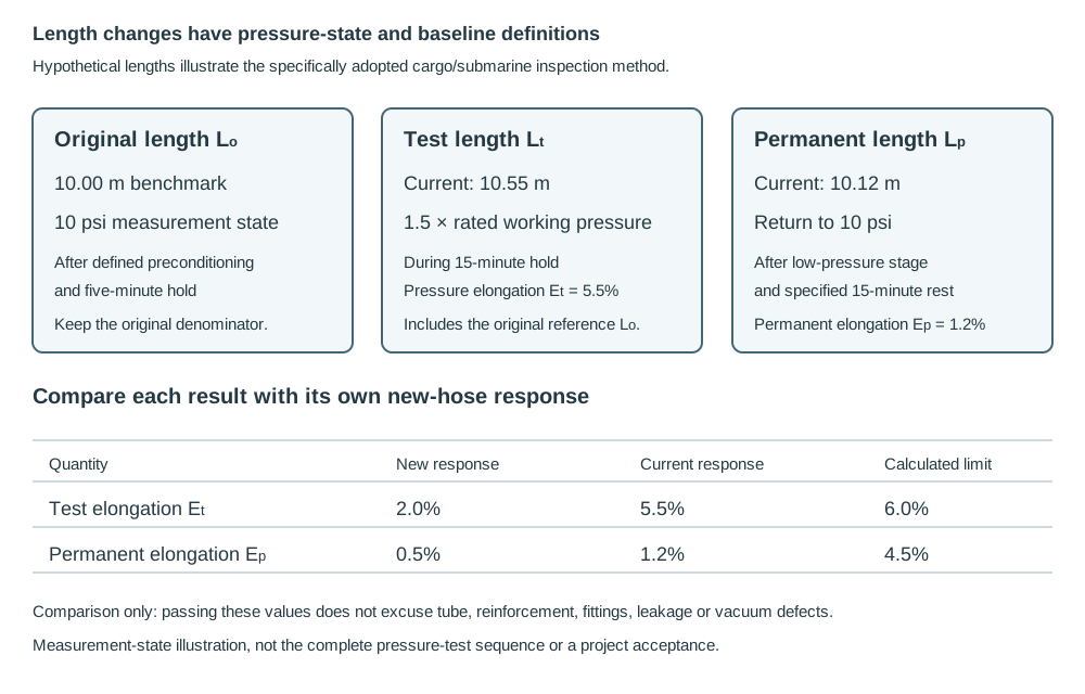
Figure 20.1. An authored measurement-state illustration using hypothetical current lengths. Original, test-pressure and permanent lengths have different definitions; the original new-hose benchmark remains the denominator. The panels do not supply the complete pressure-test procedure. Structured teaching calculations retain the new/current values, units, comparison rules and assumptions.
The 1.5-times-working-pressure inspection route is distinct from manufacture/qualification tests and actual component limits.
Give each hose test its own purpose and disposition
Hydrostatic inspection observes leakage, bulges, ridges, fitting movement and measured length response under the specified condition. A low-pressure stage can reveal a fitting leak not apparent at the preceding pressure. Vacuum examination addresses inner-tube separation, flattening and kinking. Electrical continuity addresses the conductive path needed for a particular assembly purpose. These are different warrants.
Water inside or outside the hose can provide a conductive path and conceal a broken intended bond.
The selected continuity observation uses an empty hose as dry as practicable.
In a submarine assembly, internal bonding can be part of cathodic-protection continuity. It is not automatically required for static protection, and the consequence of a loss depends on the assembly and whether it signals broken reinforcement. A different position in a string is a separate evaluated disposition, not permission to ignore an internal helix break.
Construction changes the visible damage criteria. A solid-wire-reinforced hose with a severe local kink is evaluated differently from a helix-free or kink-tolerant construction under its vacuum test. The adopted procedure gives separate criteria for these families.
A single flattening criterion cannot apply to all hose constructions, and an intact cover does not establish sound reinforcement.
External-cover-only damage in an otherwise acceptable hose can be repairable under the applicable method, followed by full required testing. Inner-tube tears or looseness, cracked fittings, broken strength reinforcement and pressure leaks lead to a different disposition. Mark and remove condemned assemblies so they cannot be confused with serviceable stock. A destructive evaluation of a retired hose can provide information about degradation. It is not a way to return that item to service.
For a cargo/submarine inspection program specifically adopting the following maximum intervals, keep the type and accessible location distinct:
Table 20.2. Conditional cargo and submarine hose inspection intervals.
| Inspection under this program |
Cargo hose |
Submarine hose that can be lifted above water |
Submarine hose at depth |
| External |
6 months |
6 months |
12 months |
| Internal |
6 months |
12 months |
12 months |
| Vacuum and hydrostatic |
12 months |
12 months |
12 months |
These are local program maxima, not universal intervals for every hose. The structured inspection table preserves their construction/service and access scope.
That program also normally requires hydrostatic assessment before reuse when a hose has been out of service and untested for more than six months. Retained-pressure/chemical/handling history still matters. Unusual stress, pressure, storm or handling damage calls for the required additional assessment before reuse. A calendar maximum is not a promise that a damaged hose remains suitable until its date, and an old manufacture test is not current-condition evidence.
Storage and cleaning preserve another state. The selected drainage/aeration/preservation method depends on the product and hose construction. Indefinite storage differs from frequent duty. Sun, ozone, retained product and a damaged cover affect the stored assembly.
Keep maintenance access and the load path available
Inspection and repair require a physical work arrangement. A filter needs room to remove its element without dropping trapped material downstream. A heavy valve needs a maintained weight path for the remaining pipe when it is disconnected. Insulation/coating access can require removable covers or a planned restoration of the barrier. An instrument bridle needs safe isolation and access to the measurement element.
Spring settings/locks, resting-shoe contact, guide clearance, bracket corrosion and movement relative to neighboring steel define the maintenance load state.
A removed or failed support can change the sustained load path before a visible pipe leak appears. Added repair weight, a seized slide or an unintended restraint can alter equipment reactions. Support assessment supplies the mechanical decision. The maintenance configuration must preserve or re-establish the relevant contacts and freedoms.
Coatings and insulation can hide or create deterioration. A support crevice retaining seawater and an insulated cold surface retaining moisture have different exposure and access conditions.
The arrangement needs access for required surface preparation, recoating and inspection.
Opening the protection to inspect also creates a restoration task. Leaving a broken vapor barrier or poorly sealed penetration can recreate the mechanism after an apparently successful wall examination.
Nonmetallic and lined systems need their own condition evidence. Metal-wall adequacy does not establish retained liner integrity. A permeated-gas annulus can affect depressurization behavior. Reinforced resin or polymer joints cannot be assessed or repaired simply by importing a metallic weld/torque method.
Material variants, installation and repair carry those detailed interfaces.
Offshore access adds restricted space, marine exposure and limited lifting/support services. A riser or under-deck line may require diver or remotely operated inspection access fixed by its original geometry. A removable spool can enable equipment withdrawal, but introduces joints and a changed load path.
Match material-condition evidence to the system that can be damaged
A metal wall, an internal lining and a reinforced-resin laminate perform different roles. A thickness reading on the steel may establish part of its containment section while leaving a damaged liner unresolved. Permeated gas retained behind a lining can create another differential-pressure state on depressurization.
The annular vent/pressure arrangement and liner condition govern that differential state; an unlined-steel corrosion allowance does not establish liner adequacy.
The maintenance consequence depends on construction. Under particular lined-system repair methods, damage to a plastic or resin liner can require replacement or relining of a complete joint/section. Under those methods, local cement-liner end damage may permit a selected patch. This distinction identifies the evidence and access needed for the proposed intervention; repair methods owns its actual eligibility and execution. A small visible defect can therefore demand substantially different preparation in two systems with the same steel outside diameter.
Reinforced thermosetting resin needs laminate/reinforcement condition evidence as well as surface observations.
Crazing, dry reinforcement, fracture/interlaminar separation and cut roving are different observations from a shallow scratch that does not expose fibers. Manufacturing visible-defect descriptions help identify those features. Their purchase-acceptance table is not automatically an in-service discard rule. For a critical high-pressure FRP application, a selected acoustic-emission assessment can be considered under its own method.
This does not make it mandatory for every resin line or an unrestricted substitute for other quality and condition evidence.
Thermoplastic fusion joints and resin-bonded joints also have different qualification, damage and repair routes. A repair sleeve/clamp acceptable under a particular low-pressure FRP method is not thereby a general pressure-pipe repair for HDPE. The relevant HDPE repair basis favors replacing/fusing the damaged section.
Cleaning and inspection can themselves damage a nonmetallic internal surface. Particular HDPE/FRP guidance permits smooth polymer pigs and excludes scraper pigs for those products.
Material behavior, inspection-tool geometry and cleaning together establish whether the chosen access and action preserve the system.
Demonstrate protective and utility function as well as containment
A protective valve's body integrity does not establish the required detection, logic, utility and final-action path. Temporary bypass/isolation can disable that function while hardware remains installed. See protective systems and measurement/control for the actual functional boundary.
Utility observations should also follow their required function. Air pressure alone does not prove dryness or remote reserve. Heater circulation alone does not prove the fluid is uncontaminated. A hot condensate discharge does not distinguish every trap failure or low-differential condition.
Consumer quality, pressure and temperature requirements remain those of the selected utility architecture.
Maintenance of a shared filter, compressor or return header can affect several consumers at once.
Service-specific restoration remains local. Oxygen work must retain clean components and the stated separation/atmosphere distinction. A chlorine water test must be followed by its cleaning/drying basis. Sour equipment opening must address deposit and material exposures. Cold liquefied-service work must preserve temperature and pressure-protection assumptions.
The general readiness method in verification and restoration connects these tasks, while service mechanisms explains why their conditions differ.