Chapter 12 — Buried piping, pipelines and offshore interfaces
Define the system before choosing its route
Piping below grade is not one engineering system. A plant oily-water sewer collects distributed drainage and depends on its internal elevations. A buried cooling-water header distributes pressurized water and must remain isolatable and repairable. A transmission pipeline connects facilities across a route whose terrain, population, crossings and operating inventory matter. An offshore riser connects that route to a moving, loaded structure through a severe marine environment.
Define the service boundary, endpoints and connections, pressure sources, receiving systems and physical environment before selecting hydraulic, structural or intervention methods. A pressure-rated line can still fail its function through an undrainable route, undermined foundation, excluded inspection tool or unassessed installation state.
This chapter keeps plant underground systems, transmission pipelines and offshore facilities/rigid metallic risers distinct. Utility architecture establishes collection, segregation and delivered service. Here the route and physical configuration must make those functions possible. Mechanical evaluation and supports and restraints explain general load and movement methods. The environmental and installation interfaces developed here supply their actual inputs.
Lay out the underground plant as an accessible network
Plant gravity drainage begins with what can enter the system and where it may go. Storm runoff, contaminated surface water, oily equipment drainage, chemical wastes and sanitary drainage have different collection and treatment requirements. Combining oily and storm drainage can save pipe while enlarging treatment duty and requiring suitable segregation against vapor or fire propagation. Separate chemical collection may be justified by material compatibility, recovery or neutralization. The preferred combination depends on the actual plant and receiving facility.
- Map the paved and unpaved catchment areas, curbs/dikes, equipment drains, continuous discharge and credible rain/fire-water cases.
A catch basin collects surface liquid and can include a sediment trap and an outlet seal. A drain hub collects an intended equipment discharge. Branches lead into sublaterals, laterals and a main. Sewer boxes and cleanouts provide access to otherwise hidden sections. Their positions must permit actual cleaning and inspection, not merely appear as symbols on the drawing.
Seals address communication through a drainage network. Under an arrangement using water seals to limit vapor/fire spread, determine which connections enter through a seal, the maintained seal depth and the behavior when flow or liquid inventory changes. Off-site straight-through mains can have different conditions from plant laterals entering a box. A seal or covered box does not itself establish an atmosphere suitable for entry.
Locate access, covers and any required vent destination with the service hazard and intervention in mind.
Prepare a below-grade obstruction plan while the plot remains adaptable.
Include foundations and their depths, existing lines, electrical/instrument ducts, trenches, light-pole bases, roads, paving and future connections.
Establish outlet and battery-limit invert elevations early.
An apparently convenient upstream route may be impossible once its downstream destination is fixed. Surface grading, catchment subdivision and collection points must be developed together so equipment foundations or access ways do not divert water away from the intended basin.
Material selection includes fluid, temperature, pressure, joining, burial and external loading. Metallic piping, iron drainage systems, concrete, vitrified clay, polymers and reinforced resin systems differ in wall dimensions, joints and resistance to handling or ground loads. A material that resists a corrosive drain may still need a particular buried support and joining design. Materials and installation carry the detailed family rules. A metallic pressure-pipe detail is not a universal buried-drain detail.
Keep secondary containment a usable second boundary
A buried drain carrying contaminants can need an arrangement that detects and collects leakage before it reaches surrounding soil. One alternative is a primary carrier pipe within a secondary containment pipe. Another can move the discharge to a pressurized aboveground route to remote treatment. They have different pumping, visibility, access and operating consequences.
- Select the actual required containment and emissions function before choosing the hardware.
In a double-containment assembly, the carrier conveys the intended fluid and its supports maintain the required position within the outer line. The outer pipe has a separate leaked-fluid/vapor collection function. FRP, lined or polymer assemblies may be prefabricated with internal supports, but the material, joints and handling must preserve both boundaries. A carrier joint that passes inspection does not establish the secondary joint, penetration or collection path.
Sewer-box transitions need particular care. The carrier penetrates a wall while the secondary barrier continues across the pipe/box interface.
- Provide a defined means of draining collected leakage and detecting vapor where required, with access to clean the collection line and inspect the barrier.
A small detector line connected at the wrong location or a collection pocket that cannot be emptied can leave the second boundary present in the drawing but ineffective in service. Permanent and portable detection arrangements have different observation and maintenance demands.
A below-grade trench is another physical arrangement from a directly buried line. Insulated or traced piping, valves and drains can remain accessible within it, but trench width, cover type, traffic, drainage and service exposure must suit the work performed there. Electrical/instrument ducts and pull points also need reserved space: a duct exit that later becomes covered by piping or a maintenance laydown area can lose its required access.
- Complete the underground composite with the actual drain points, line/reference elevations, joint/terminal details, crossings, foundations, duct space, cover, box schedules and new-to-existing interfaces.
Before covering the installation, verify the connections and recorded route against that arrangement. The carrier, secondary barrier and any detection/collection system must retain their intended separate functions through testing, restoration and later repair. Construction, readiness and technical records carry the general methods.
Trace carrier flow, collection and observation through the interface
Trace carrier fluid separately from leakage/vapor entering the secondary space. Sensors require their specified observation conditions; removal requires a communicating drain to a suitable destination. Neither supplies the other function or a seal.
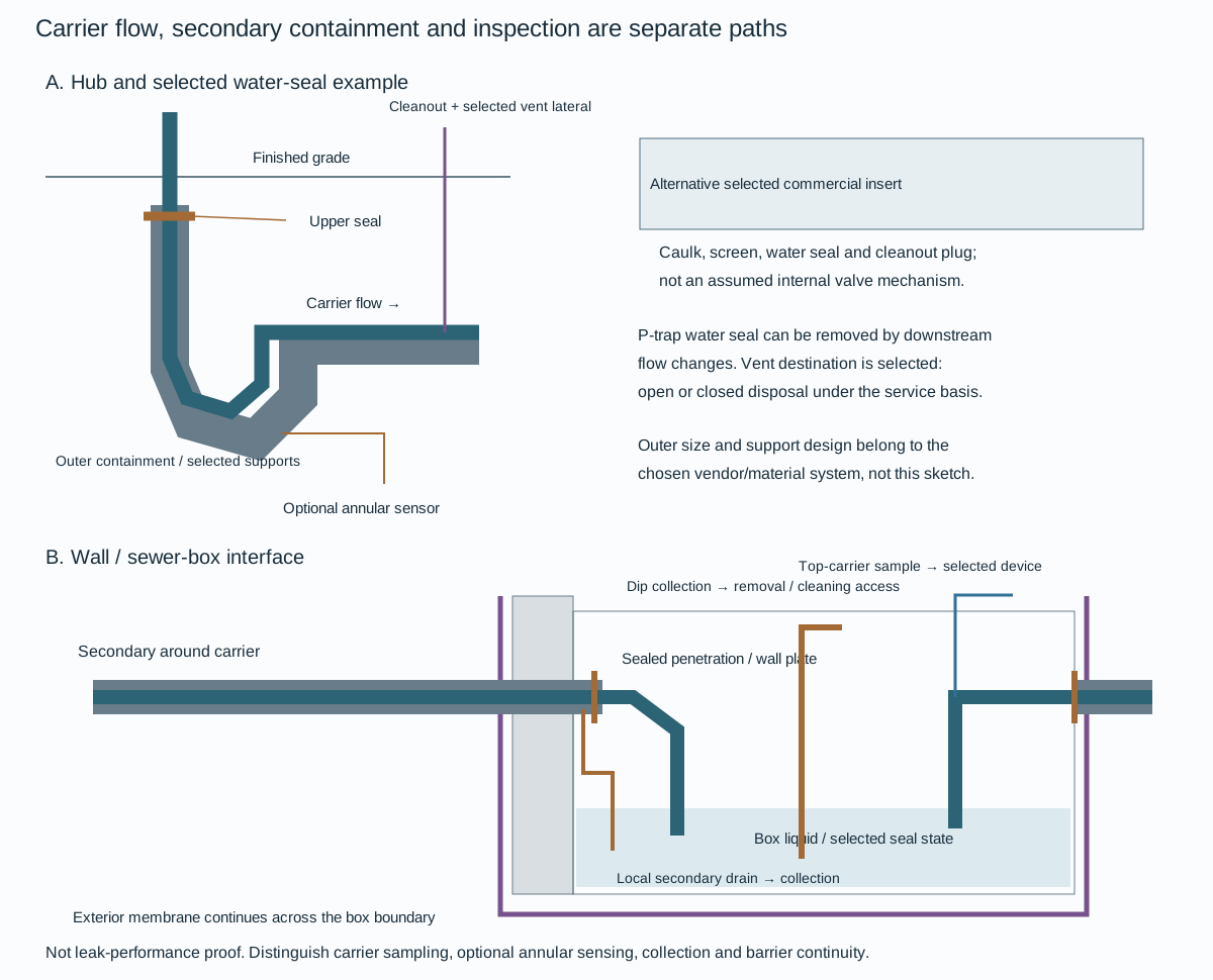
Figure 12.1. Selective functional sections derived from drain-hub and sewer-box arrangements. Carrier flow is distinct from the outer containment, hub upper seal, wall seal/plate and exterior membrane. The box's local secondary drain, dip collection line and top-carrier sampling connection have different endpoints. A separate optional annular sensor is shown at the hub. The commercial water-seal insert is an alternative, not an invented internal valve. These sketches carry no default pipe sizes, collection capacities, leak-tightness guarantee, detection coverage or regulatory compliance result.
At a hub, the carrier can pass through a P-trap while the outer pipe encloses the connection. An upper carrier/secondary seal terminates the annular boundary. That upper seal is distinct from the liquid vapor seal maintained by the trap.
- Select the position and construction for the real fluid level and containment duty.
The carrier-positioning supports and outer pipe size belong to the chosen prefabricated vendor/material system. FRP, lined and polymer combinations have different joint, support and handling requirements. A typical sketch supplies neither generic support spacing nor a substitute for the two-boundary construction checks.
A water seal can be lost when variable downstream flow withdraws it. Vent communication therefore belongs with the selected carrier/cleanout arrangement. The vent lateral shown in the functional section communicates with the drain path through the cleanout connection and needs its seals and accessible plug.
- Select an open or closed disposal destination under the service and emissions basis.
An open arrow on a layout is not permission to release a contaminant. A running trap, sewer-box seal or selected commercial hub insert is a different alternative. The insert arrangement includes caulking, a screen, water seal and cleanout plug, with debris-removal access. No additional internal mechanism is inferred.
At a sewer-box wall, the carrier penetrates a separately sealed outer assembly. A wall plate and the exterior polyethylene membrane example address different barrier interfaces. The local drain from the secondary side provides a route for material entering that space. A dip collection line reaches the box's lower liquid region and remains accessible for removal and cleaning. The box can also receive the intended carrier effluent.
A collection path does not, by itself, guarantee segregation of a leak from that effluent or establish adequate collection/storage capacity. The adopted receiving and removal method must match the actual material and state.
Observation paths need their own endpoints. The top-of-effluent-carrier sampling connection through the box top permits attaching a portable device for periodic checks or installing a separately selected permanent arrangement. It is distinct from an optional sensor located in the hub's annular space. Sampling the carrier does not automatically monitor the entire annulus, and one sensor does not prove coverage of every joint, pocket or box penetration.
- Retain the device's selected location, access, response basis, periodic or continuous observation duty and maintenance requirements with the installed assembly.
Before covering or restoring the system, verify both boundaries, the sealed penetrations, support positioning, collection communication and accessible inspection/cleaning paths. A changed carrier route or seal can alter where a leak collects. An inaccessible cleanout or blocked local drain can defeat an otherwise intact drawing.
- Preserve the installed geometry and separate barrier, collection and detection evidence through later repair.
These interfaces explain the containment functions. They do not establish complete leak performance or satisfaction of a current environmental requirement.
Preserve the invert and account for the outside envelope
The invert is the elevation of the inside bottom of a gravity line. It is a useful constant across pipes whose wall thicknesses differ. A construction dimension to centerline or outside bottom needs an explicit conversion. Maintaining the wrong reference can create a step inside the drain or miss a crossing clearance.
For a circular pipe with internal diameter , wall thickness and invert elevation , consistent geometrical relations are
, and are centerline, outside-bottom and outside-top elevations. All elevations and dimensions use m on one datum. The relations assume a circular section with the stated wall thickness. Sockets, hubs, insulation or another local envelope need separate clearance checks.
For a uniform downward invert grade over horizontal distance , the downstream invert is . Grade is dimensionless when fall and horizontal distance use the same units. A slope stated for a particular chemical drain or sewer procedure must stay with that arrangement. It is not a minimum for every liquid line.
At crossings, apply required separation to the actual outside/joint envelope, allowing for excavation, settlement and construction tolerances.
A reducer or a change of material can change the relationship between the outside envelope and the invert.
- Follow the internal bottom through the joint and fitting, with the applicable bell/spigot orientation and available reducer pattern.
An internal projection can retain solids or create a weir. An invert schedule should therefore carry actual pipe dimensions and fitting transitions, rather than use nominal size as though it defined every internal surface.
Coordinate excavation, foundations and the line that can move
Gravity routing consumes elevation as it proceeds. A pressurized water line can often rise or fall locally to clear it, whereas introducing an arbitrary rise in the sewer can destroy its intended gravity path.
- Use that difference when allocating crossing space.
A lift station is another arrangement, with pumping, power, overflow and maintenance duties. It should be selected deliberately rather than hidden in an unworkable gravity profile.
Spread footings depend on the supporting soil. A route outside the footing in plan may still require an excavation that removes that support at depth. A simple 45° exclusion sketch appears in one layout basis, but it is a scoped preliminary coordination aid, not a geotechnical rule for all soils or excavations.
- Establish the actual foundation/soil/excavation condition and evaluate the alternatives: reroute the line, change elevation, revise the foundation, or provide the required excavation support.
A pile-supported foundation changes the load-transfer problem. It does not eliminate every excavation, access or buried-service concern.
Pressure-water routing can preserve rack space and shorten exchanger laterals when headers are close to channel ends. Aboveground routing improves direct access but can enlarge racks and branches. Buried hot return and cool supply also interact through soil heat transfer. Leave practical space for joints, tools and future excavation while maintaining channel removal, roadway and electrical-duct access. The most compact initial drawing may have the largest repair cost once the line is covered.
Fire-water loops and section valves need a configuration that preserves the required coverage during repair or isolation. Cooling-water supply/return and potable connections must retain their distinct functions.
- Plan the below-grade-to-aboveground transition, the applicable joint and terminal elevation, supports and the division of installation responsibility.
A bevel end or buried flange at the agreed interface is part of the installed arrangement, not an unresolved drawing handoff.
Calculate drainage duty and hydraulic state together
For a rational runoff estimate, a useful SI expression is
In this equation, rainfall intensity is in mm/h. Catchment area is in m², and runoff coefficient is dimensionless. The conversion follows from rainfall depth times area: 1 mm over 1 m² is 1 L.
- Add the applicable continuous process drainage on the same flow basis.
The coefficient represents the selected catchment behavior. It does not account for every obstruction, temporary blockage or receiving-system constraint.
One adopted drainage procedure uses runoff coefficients 0.9 for paved and 0.5 for unpaved areas, with a 1.1 sizing factor on combined rain/process flow. That factor is not an independent 10% rainfall depth on each term. The procedure evaluates rain/process flow at 75% full and fire-water/process flow at full flow. Retain the fill-state criterion and actual plant rainfall/fire-water basis; the larger numerical flow alone does not complete pipe selection.
Fixed allowance values used in a particular layout example are not a substitute for a deluge or emergency-demand assessment.
The Manning uniform-flow method relates capacity to area, hydraulic radius, roughness and energy gradient. Expressed on an SI dimensional basis,
In these equations, is mean velocity in m/s. is flow in m³/s, and is flowing area in m². is wetted perimeter in m, and is hydraulic radius in m. is the dimensionless energy gradient. For the assumed uniform gravity-flow state it is taken equal to pipe grade.
is the conventional Manning roughness parameter, with s/m as the dimensional basis of this SI expression. The model does not resolve a backwater, surcharge, abrupt junction or an entire transient network merely by inserting the floor slope.
For a circular full section, and . Roughness, solids, joints and maintained internal condition affect performance; a clean/coated chart basis is not an aging-line assessment.
The 75%-full rain case needs the partially filled circular area and wetted perimeter. It is not established by multiplying full-flow capacity by 0.75: the hydraulic radius changes too. For a circular segment of liquid depth , its geometry can be expressed as
Depth and diameter use m, and is the wetted central angle in radians. This is geometric construction of the assumed circular flowing section, not another empirical hydraulic criterion. Identify the governing fill convention before interpreting a percentage. Verify velocity/self-cleaning and receiving-boundary conditions for the complete network.
Low operating flows also matter. A line sized for a large emergency event can retain sediment at ordinary drainage duty. The structured teaching calculations preserve the inputs, results and limitations without selecting a plant pipe size.
Define the transmission pipeline and its operating envelope
A transmission pipeline connects facilities over a route. Under one specifically adopted pipeline definition, it extends from pig trap to pig trap, including their pipework/valves, or to the designated first isolation valve where no trap is fitted. The connected plant equipment remains outside that defined pipeline boundary. Flowlines from off-plot wellheads can fall inside it, while piping within a producing facility has its own equipment, layout and pressure-design context.
- Draw and retain the actual code and engineering interfaces rather than assign scope by distance or pipe diameter alone.
Within a producing facility, removable piping around wells can preserve workover space, and planned future connections can avoid later interruption of a crowded operating area. Supports must prevent unintended liquid pockets and equipment connections need their flexibility/misalignment assessment. Those facility duties do not disappear when a connected off-plot flowline is assigned to a pipeline boundary.
The governing code edition, fluid category, jurisdiction and adopted supplements must be established for that boundary. One example pipeline procedure supplements the 1992 editions of ASME B31.4 and B31.8 with its adopted amendments. It classifies a fluid at ambient temperature and atmospheric pressure plus 0.5 bar, rather than solely by its transported phase. Its groups A/B have vapor pressure below 1.5 bar absolute at ambient temperature: A is nonflammable, stable and nontoxic. B is flammable, unstable or toxic.
Groups C/D have vapor pressure above 1.5 bar absolute: C is nonflammable, stable and nontoxic. D is flammable, unstable or toxic. Under that particular procedure, A/B use its B31.4 route and C/D its B31.8 route. Its explicit amendment places LPG and anhydrous-ammonia transmission in its B31.8 route even while noting their B31.4 coverage. That is a particular adopted classification/assignment, not a new universal rule for those products.
It should remain an explicit alternative wherever that practice governs.
- Establish pressure and temperature profiles for steady and transient conditions over the projected life.
Maximum throughput and turndown can create different duties. Low flow can permit water dropout, deposits or changed inhibitor distribution. High velocity can increase erosion or disrupt protective films. Shutdown, startup, pigging and flow changes can move liquid inventory toward downstream equipment. A pressure calculation at one nominal flow does not describe all these states.
For a liquid route, hydrostatic head and friction can change which location governs pressure. Designing different route sections for different pressures requires assessment of credible adjacent-section overpressure. In a gas route, pressure segmentation can also reduce useful line-pack flexibility. System conditions and pressure protection develop the general distinctions. The route establishes where they have to be applied.
The operating philosophy supplies practical inputs: staffed or remote operation, communications, access, pigging purpose/frequency, maintenance bypasses, integrity monitoring, foreseeable shutdown and final abandonment. These decisions affect physical hardware and route long before handover. A continuously required line needs a deliberate means of servicing a component that cannot remain in operation. An unplanned temporary bypass is a changed piping configuration with its own basis.
Choose the route with construction and intervention in view
A route survey has different tasks onshore and offshore. Onshore work needs topography, roads/railways/rivers, occupied buildings and future development, soils, subsidence, resistivity and environmental conditions. Offshore work adds bathymetry, rock/coral features, seabed properties, currents/waves, fishing/shipping activity, other installations and concession constraints. The survey should identify the features that construction must preserve or reinstate as well as the geometry on which the analysis relies.
Population/location classes and separation assessments affect particular pipeline design bases. They must stay attached to the applicable fluid/code scope. Neither a sparse route nor a low nominal pressure eliminates every release consequence.
- Consider emergency access and the environmental sensitivity of a release along the whole route, including places that are difficult to reach or isolate.
Route curvature, crossing angle and spacing interact with the installation method. A gentle foundation route may be followed by elastic bending, while sharper changes require a specified field/hot bend and its qualified geometry. An offshore crossing chosen only for minimum distance can conflict with installation, anchoring or future access. Approaches to a platform need space for tie-in and construction vessels and protection from marine activity. Shore and major-river transitions require a defined construction/environmental boundary.
Pipelines in permafrost or arctic conditions need considerations outside the ordinary route basis described here.
Soil and water participate in mechanical behavior. Burial can restrain expansion, alter load distribution and hide corrosion or movement. Subsidence, landslide, scour and seabed settlement impose a changed configuration. An offshore pipe can develop free spans. Weight/buoyancy and hydrodynamic loads affect stability.
Ground contours, crossing protection and cover are therefore analysis and inspection inputs, not only civil dimensions.
Use an initial route screen before completing the risk assessment
An initial occupied-building route screen requires fluid classification, pressure and geometry. Final assessment still needs failure likelihood, release/ignition, population and exposure over the line’s life, plus crossing and emergency-access consequences.
One historical pipeline planning method provides two unit-bound expressions. With design factor not exceeding 0.72 it uses
For the method's design-factor category not exceeding 0.4 it also provides
In these expressions, is distance in meters. is pipeline diameter in mm, and is wall thickness in mm. is maximum allowable operating pressure in bar gauge. is the method's dimensionless fluid factor, distinguished here from volumetric flow. The numerical coefficients contain this empirical unit convention.
Metres, MPa or psi cannot be inserted without transforming the method. Its design factor is the ratio of pressure hoop stress at design pressure to specified minimum yield strength, not a general safety multiplier.
Within this planning basis, take mm when diameter is smaller and bar gauge when operating pressure is lower. Thickness below 9.5 mm may be represented by 9.5 mm. Thickness above 13.5 mm shall be represented by 13.5 mm. These are input conventions of the screen rather than changes to installed wall. The fluid factors are 0.3 for its category C.
Within category D, they are 0.5 for methane, 0.8 for ethylene, 1.0 for LPG, 1.25 for NGL, 0.45 for hydrogen and 2.5 for ammonia. Its categories A/B carry zero factor under this particular building-distance method, while construction and operating access remain required. Zero factor does not remove other hazards or create a zero-separation rule for another service or design basis. The structured route method keeps the definitions and category conditions together.
The two written design-factor inequalities can overlap. Establish the applicable expression under the adopted basis; do not select the smaller distance solely for that overlap.
Unknown-fluid analogy also requires the actual hazard basis, rather than choosing the smallest quoted factor. Final routing follows the quantitative risk assessment and applicable requirements. The screen alone does not approve an occupied-building setback.
Make protection inspectable and retain its distinct mechanisms
External coating limits environmental contact. Cathodic protection addresses exposed metallic areas within its electrical and environmental conditions. Under an adopted metallic buried-pipeline basis, both can be required, with electrical isolation and monitoring provision arranged so their effectiveness can be demonstrated. Offshore submerged, splash-zone and atmospheric portions have different protection duties. More cathodic potential is not automatically better: excessive protection can introduce hydrogen-embrittlement concerns in susceptible material.
- Protect coating during storage, handling, lowering and backfilling, and provide the required field-joint restoration/inspection.
A coating selected well in design but cut by handling or damaged by backfill changes the installed corrosion basis. Support contacts and insulated sections need arrangements that avoid retained moisture and permit inspection. Coatings and corrosion management explains selection/application methods. The route and construction states determine their local exposure.
Internal corrosion depends on the transported fluid and its flow regime. Water, deposits and inhibitors may reach different locations as throughput declines. A probe or coupon can give local evidence without proving the entire line's condition. Pig debris is qualitative evidence rather than a general corrosion-rate measurement. Where the operating basis requires full-route internal assessment, inspection-tool access and geometry must have been provided.
Operating integrity develops the assessment and response. This chapter establishes the physical access.
Internal coatings, linings and corrosion-resistant pipe are different alternatives. A coating with holidays cannot be credited as complete prevention of corrosion. A lining needs compatibility and continuity at joints, and gas permeating into an annulus can create a collapse problem when the line is depressurized unless relieved by the evaluated arrangement. Nonmetallic and flexible pipelines can be useful for specific services, but their joining, restraint, collapse and testing rules need their own basis. The rigid metallic rules developed later are not silently extended to them.
Isolation divides inventory and separates a route from a plant incident. Sectionalizing valves address line releases along a route. An emergency valve at a facility interface has another role. Closure and leak detection should be assessed for actual consequences, available actuation and the contained inventory, rather than infer complete leak-tightness from a valve symbol. Blowdown introduces temperature, discharge and access conditions of its own.
Control pressure and protective pressure limits also differ. A regulator maintaining normal inlet pressure does not by itself protect the pipeline against its failure. Credible source overpressure, surge after valve closure and thermal expansion of trapped liquid require their appropriate evaluation. The maximum transient pressure can occur upstream of the initiating closure, especially in a hilly liquid route. Defined allowable operating and incidental pressures have different frequency/duration bases.
They must be assessed at every consequential location.
Carry pressure, restraint and shear into the pipeline stress question
Wall derived from pressure hoop stress still has to carry longitudinal and shear demands under the actual functional and environmental loads. The restraint representation changes the longitudinal stress: the fully restrained thermal case is different from a free-expansion case carrying bending. A pipe with partially mobilized soil resistance, a flexible spool or changing contacts cannot simply inherit either limiting expression as its complete model.
One adopted historical pipeline stress method combines components as
Its limiting longitudinal expressions are
These expressions apply to fully restrained and fully unrestrained pipe respectively. Its combined shear expression is
Use one consistent dimensional basis:
- and stresses in MPa (N/mm²).
- Diameter and wall in mm.
- Modulus in MPa and thermal coefficient in K⁻¹.
- Installation-to-operation temperature difference in K or °C difference.
In these expressions, is Poisson's ratio. is applied bending moment, and is applied torque, both in N·mm. is pipe section modulus in mm³. is shear force in N, and is pipe-wall area in mm². The signed longitudinal component is retained in the equivalent-stress cross term.
- Do not substitute a fluid area for the pipe-wall area or insert nominal size as though it were the required diameter.
The component method and examples preserve these quantities.
Nonzero torque or shear adds another component and must use its actual load/sign combination.
Under that method, operational calculations use nominal wall excluding corrosion allowance. Installation, hydrotest and operation have separate functional/environmental combinations and local equivalent-stress fractions of yield: 96%, 100% and 90%, respectively. Its installation provision explicitly excludes methods in which yielding is integral, including reeled pipe and rigid riser pull-in through a J-tube. These historical fractions do not qualify a new project or replace checks for collapse, fatigue, local attachment demand or a strain-based installation method.
Mechanical evaluation establishes the real restraint/contact and load representation. This method shows how that representation reaches a pipeline component-stress calculation.
Give pigging hardware its intended operating functions
A pig trap allows insertion/launch or receipt/retrieval of a pig while the connected system follows its defined operating arrangement. The barrel contains an enlarged major section for loading or removal, a reducer, a minor section and an end closure. Actual internal clearances matter: nominal barrel oversize can be consumed by wall thickness, fittings or the inspection tool's geometry.
The connecting lines have different functions:
Table 12.1. Pigging connection functions.
| Connection or item |
Function that the arrangement must establish |
| Facility bypass |
Continue the selected pipeline/facility flow path |
| Kicker line |
Divert fluid through the barrel for launch or receipt; connection position depends on trap direction/type |
| Balance line |
Fill/pressurise both sides of a pig without unintended motion |
| Pressurising line |
Control filling or pressure equalisation where required |
| Drain points |
Remove and verify accumulated liquid, including trapped regions near a pig |
| Vent/blowdown points |
Relieve/purge the relevant spaces, including a region isolated by a stuck pig |
| Thermal relief |
Protect a trapped-fluid pressure case |
| Pig signaller |
Give location/pass evidence at its actual installed point |
The structured pig-trap function table preserves these purposes and the geometry/condition qualifications. This is not a valve-operating sequence.
A launcher kicker located toward the closure and a receiver kicker toward the reducer do not perform identically. Bidirectional arrangements require their own selected connection design. A balance connection can prevent a loaded pig moving into a valve or losing its seal as the barrel fills. A small pressurizing bypass can permit controlled equalization but must not defeat a required shutdown boundary. The location and control functions should be drawn coherently instead of assigning one generic branch to every purpose.
Drain and vent placement must reach both sides of a potentially obstructing pig. A tell-tale drain gives evidence that liquid has been removed. Drain diameter, slope and sphere position also affect blockage. A vent near the closure alone may not depressurize the region behind a pig stuck in the minor barrel. Pig traps can contain air or air/hydrocarbon mixtures during intervention, so a flare connection needs that composition case as well as its ordinary pressure duty.
The receiving drain can be exposed to blow-by; collection architecture and protection remain connected to the physical trap.
Draw the connections around the spaces a pig can isolate
The facility bypass joins the main tee to the adjoining facility boundary. The kicker diverts fluid between that bypass and the major barrel. The balance line branches from the barrel side of the kicker path to the minor barrel near the trap valve. This makes simultaneous filling and pressurization of the two sides of a loaded pig a distinct function from the main diverted-flow path. A separate small pressurizing bypass around a kicker valve can serve controlled equalization where that arrangement is adopted.
It is not a replacement for the balance connection across the pig.
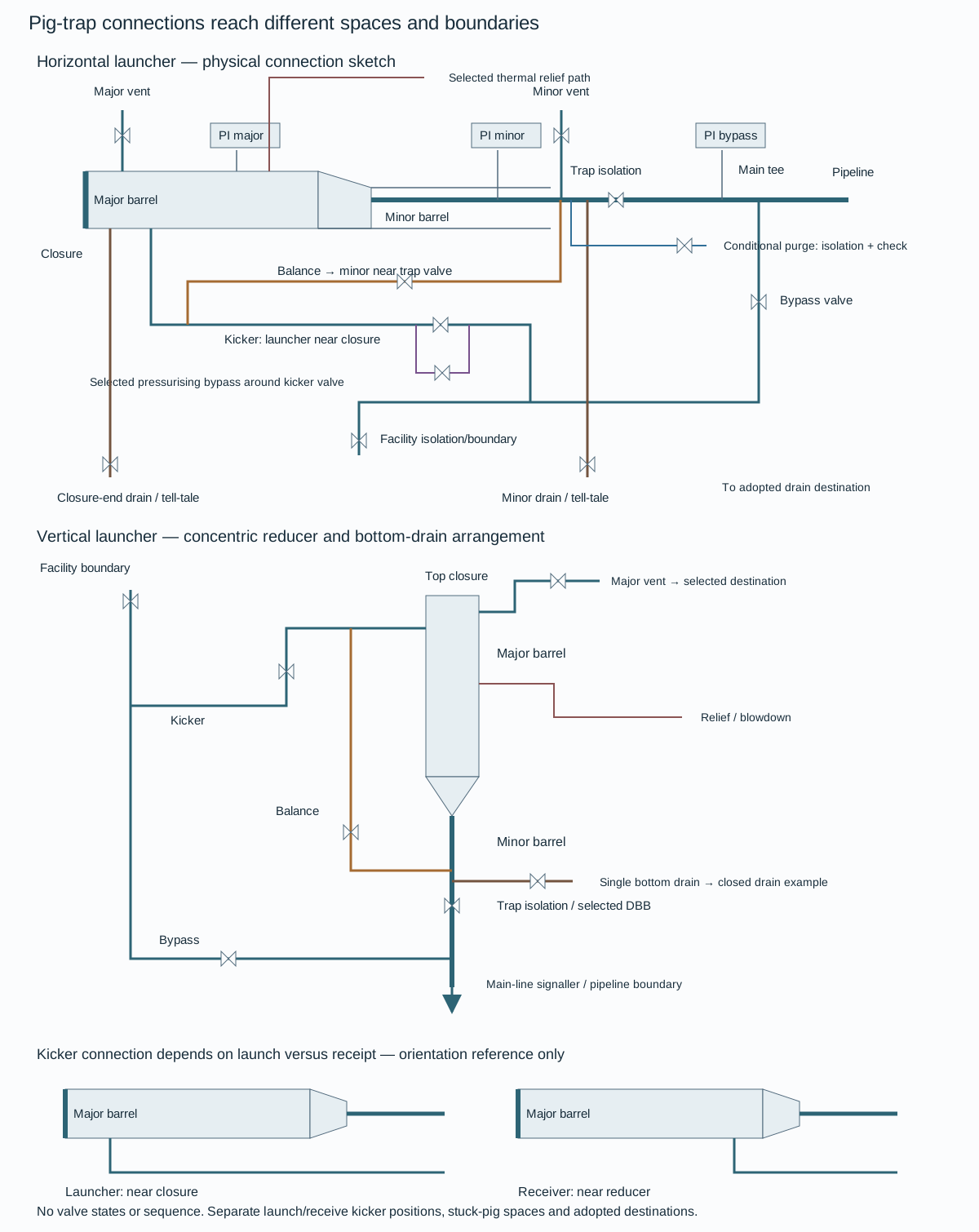
Figure 12.2. Functional horizontal and vertical launcher views, with a launcher/receiver kicker-position inset. The horizontal view retains major and minor vents, drains, pressure indications, a conditional purge connection, thermal-relief path and pressurizing bypass. The vertical view shows the concentric reducer, lower drain and selected vent/relief destinations. Valve symbols identify hardware interfaces and imply no open/closed state or operating sequence. These are connected functional views, not complete P&IDs, shutdown logic, capacity calculations or isolation proof. Structured endpoints, conditions and boundary roles and the native drawing implementation keep the distinctions recoverable.
- Consider a pig lodged in the minor barrel.
A vent connected only near the end closure communicates with the closure-side volume. The pig can obstruct communication with the volume near the trap valve. The horizontal arrangement therefore retains a vent on the minor side as a separate pressure-release path, together with the corresponding pressure indication. Drains near both ends address liquid pockets rather than prove gas pressure is relieved. A tell-tale connection supports checking the liquid state but does not demonstrate that every trapped compartment is empty or depressurized.
A blocked tapping or shut branch changes the actual connectivity represented by the sketch.
Orientation changes the physical endpoints. In the depicted horizontal method, drains connect at the bottom, while vents, pressure indications, relief, purge and signaller connections occupy the top quadrant. Kicker, balance and bypass connections use a side position or a separately selected top position. Sphere receivers can require the top position to avoid drawing a sphere into an outlet. The major/minor reducer has bottom alignment in the eccentric horizontal example.
A vertical launcher uses a concentric reducer and a single lower drain near the trap valve. Its closure-side vent and lower liquid-removal path serve different locations. The bottom drain of this offshore example connects to a closed drain. Neither rotation of a horizontal sketch nor the availability of one low point establishes a universal receiver arrangement.
- Keep launcher and receiver details distinct.
A launcher kicker connects close to the closure. A receiver kicker connects close to the reducer. A bidirectional trap needs its selected intermediate or twin-kicker arrangement. A launcher balance line prevents unintended forward movement into the trap valve or backward loss of the pig seal as the barrel fills. The corresponding receiver connection is considered where a differential across a received pig must be avoided.
Passage signallers supply evidence at their installed points. The selected tool length and actual cup locations still determine whether that evidence means the tool has cleared a tee or valve, as developed in the tool-envelope method below.
The illustration also leaves service selections visible. The horizontal source arrangement uses weld-end main isolation and flanged other-valve examples. The vertical example uses flanged valves and selected double-block-and-bleed locations. Those are distinct hardware examples, not one universally required connection type. An offshore riser shutdown valve outside the depicted trap boundary remains an interface to the pipeline system.
Any small equalizing path around a shutdown boundary must retain the adopted protection requirements rather than create an unexamined bypass. Chemical injection is absent from the illustrated vertical example and is separately selected where required.
Destinations are part of the model. A drain connects to a closed system or a specifically designated open drain under the adopted service basis, with receiving-system pressure and possible blow-by evaluated. A vent, flare or controlled-blowdown connection needs its selected destination, air/hydrocarbon-mixture case and capacity basis. The existence of a nozzle does not permit atmospheric release. A thermal-relief connection addresses an identified trapped-liquid pressure case under the adopted relief method.
No relief sizing or automatic depressurization follows from its appearance in the drawing.
Opening the closure requires the actual isolation, liquid removal, pressure and atmosphere conditions under its approved intervention arrangement, as developed below.
Treat opening a closure as a changed containment state
An end closure creates a large opening when released. Its pressure lock prevents opening under pressure, while an accessible, non-blocking safety bleeder addresses residual pressure. These devices have different duties and must remain usable rather than easily bypassed or fouled. A selected valve/closure interlock can add protection depending on service, trap location and pigging frequency. It does not replace verification of the actual pressure/contents state.
Pressure indication is evidence at a connection, not proof that every compartment is relieved. A stuck pig, blocked vent or liquid head can make the barrel's actual state differ from a single gauge reading.
Establish the applicable isolation, drainage, pressure verification and atmosphere/control conditions in the approved operating arrangement.
Do not combine the release sequence of one trap or service with another merely because both have a quick-opening door.
Plan access for the pig, closure swing/removal, handling equipment, inspection and valve overhaul.
Heavy or long intelligent pigs can change barrel length and handling demand. A trap installed to fit a short cleaning pig may be unable to accept the later inspection device without modification. Future integrity intent should therefore inform the original configuration and the as-built record.
The required tool defines more than an overall length.
- Establish its actual body, driving-cup/disc positions, mass, permitted bend/bore transitions and handling arrangement.
A receiver must bring the tool into a position where its cups no longer obstruct the required fluid path and where it can be retrieved. Space measured from the wrong branch or reducer can appear ample while leaving a cup across the intended route.
An adopted trap method distinguishes the launcher's major and minor straight lengths from the receiver's kicker-connection-to-end length and minor straight length. Those references matter when interpreting its length data. The method asks for the longest pig to be used plus a 10% margin, while its tabulated intelligent-tool dimensions separately account for cup position and historical extreme tool envelopes. Many tabulated barrel values equal the quoted overall tool length. The 10% instruction cannot be assumed already included in every cell, nor can the whole table be repaired by silently adding 10%.
- Use the actual selected tool and resolve the applicable dimension basis before fabrication.
The method separately provides external withdrawal space of tool length plus approximately 1 m. Its lateral work spaces are 0.9 m on each side for its 4–32 inch pipeline category and 1.5 m for 34 inch and above. These differ from barrel-length margins and do not establish crane, trolley, closure-swing or operator access.
Loading trays add mass beyond a tool-only weight.

Figure 12.3. Authored launcher/receiver reference sketch. The tool and cups are hypothetical. The launcher signaller is beyond the main tee by at least the selected maximum tool length under the depicted method. The receiver signaller has a corresponding minor-barrel distance from the trap valve. The receiver kicker-to-end dimension is distinct from its entire major barrel. Structured geometry data retains those references and the teaching envelope; the sketch gives no valve-opening sequence or fabricated dimensions.
A signaller reports passage at its location. For a launcher, this method places the downstream signaller at least a maximum tool length beyond the main tee to confirm passage through both tee and trap valve. For a receiver, it places a signaller in the minor barrel at least that distance from the trap valve. A closer indication can occur while a long tool still occupies an important interface. Offshore space and ESD constraints can require a separately agreed location.
- Do not describe its signal as proof of the longer clearance unless the geometry establishes that meaning.
Branch spacing also interacts with cup/disc separation.
- Avoid an arrangement in which openings coincide with the cup spacing and let the pig stall.
Spheres and soft foam tools can need different tee and catching-basket treatment. A basket can keep a received foam pig out of the kicker line while adding its own retrieval/debris duty. Nominal oversize alone does not establish actual barrel ID with thick walls, and the chosen intelligent tool's current requirements remain separate from historical extreme tables.
- Keep the final tool set, references, supports and passage meaning with the installed record.
A barred tee excludes a pig from the internal side-branch opening while preserving passage along the run. The relevant interface is inside the fitting: the swept bore seen by the tool, the branch mouth, the shaped bars or bridge arrangement and their attachment to the tee. An external tee symbol or a nominal size does not describe that interface.
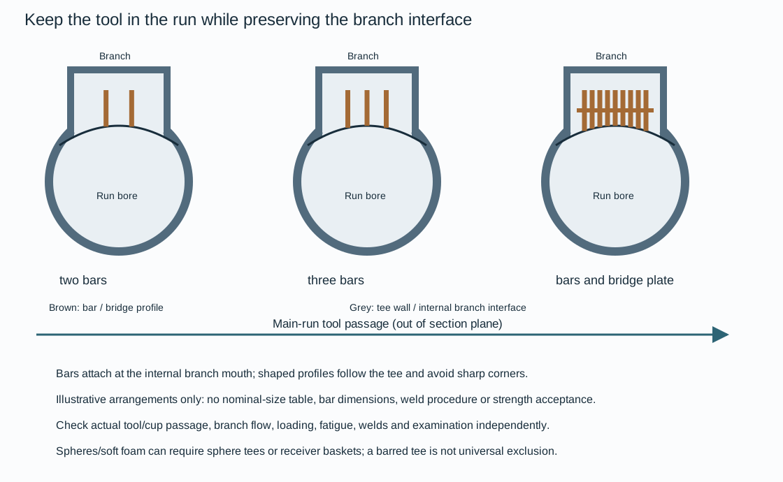
Figure 12.4. Qualitative two-bar, three-bar and larger bar/bridge-plate arrangements at an internal branch mouth. The curved profile represents the run-side interface; tool passage is normal to the illustrated section. The patterns explain exclusion geometry and are not fabrication selections for any nominal size. No thickness, spacing, bar count rule, weld procedure or load capacity is specified by this figure.
- Fit the profile to the tee curvature and installation angle, removing sharp corners that can catch or damage cups, discs or tool features.
The illustrated attachment basis includes a full-penetration weld detail, but the actual weld design, procedure and examination belong to the adopted material and fabrication requirements.
- Evaluate tool impact/loading, attachment strength and fatigue independently from clearance.
- Evaluate branch flow separately: a barrier that stops a tool can also alter flow area, collect debris or create a local restriction.
The suggested geometry is not a complete procurement specification.
The tool type can change the appropriate alternative. Spheres and soft foam pigs can stop, suffer damage or be lost at normal or barred tees. A selected sphere tee uses a perforated internal pipe to retain the sphere while allowing side-branch flow, with fabrication and possible corrosion/drainage consequences. A receiver catching basket can keep a sphere or foam tool out of the kicker line, but adds its own collection, retrieval and debris-removal duty. None of these alternatives establishes universal passage or exclusion from a drawing alone.
- Examine the actual selected tool and its cups/discs against the tee and adjoining bore, rather than optimize bar spacing in isolation.
Branch spacing that coincides with cup/disc separation can undermine the intended drive or let the tool stall.
- Retain the tool set, dimensions, material and attachment/examination basis in the selected design and installed record.
A later inspection tool or softer cleaning tool reopens the affected interface even when the pipe and nominal tee size are unchanged.
Separate slug arrival, gas–liquid separation and liquid storage
A two-phase pipeline can deliver liquid steadily, displace accumulated liquid during a flow increase, or send it ahead of a pig in a short interval. Those modes differ in volume, rate, gas content and droplet behavior. The downstream slug catcher has to separate phases while accommodating the liquid imbalance and providing the required supply to its liquid-treatment system.
A vessel-type catcher can use a relatively compact footprint. Large required storage can make a multiple-pipe arrangement attractive. A multiple-pipe catcher uses primary bottles for separation and storage, with secondary bottles serving storage. Its countercurrent displacement of gas and liquid can promote carryover if the geometry and arrival rate are unsuitable. A parking-loop arrangement separates the compact separator from a long storage loop and can save platform space by locating storage elsewhere. It relies more strongly on its selected controls and operating sequence.
These are alternatives with different plot, manufacture and operation consequences, not three equivalent ways to provide nominal volume.
In the multiple-pipe arrangement, flow splits from an inlet manifold through downcomers into primary bottles. Reduced velocity and appropriate downward inclination encourage stratification. Droplet settling needs residence length before gas rises toward the outlet. Bends and impingement can also deposit droplets, while tee orientation affects phase separation. The relative importance of these mechanisms changes with gas velocity and droplet size.
A geometry suitable for slow pig arrival can be inadequate for mist-bearing steady flow.
One multiple-pipe hydraulic approach assigns high-flow separation to the horizontal primary-bottle section before the gas risers. An older approach placed more of that demand on very large risers. These approaches have different length and riser-size consequences and should not be averaged into one dimension rule.
- Retain the selected separation model, required performance and physical fluid properties when choosing bottle count and geometry.
Keep separation and storage paths identifiable
Separation and storage paths must remain distinct when nominal vessel/pipe volume is converted into usable inventory.

Figure 12.5. Authored functional alternatives for a vessel separator with separate surge drums, a multiple-pipe arrangement with primary and secondary bottles, and a separate-separator/parking-loop storage concept. The vessel view keeps liquid transfer and displaced-gas return distinct. The multiple-pipe plan identifies the primary entrance separation region, downstream storage, gas-riser path and lower liquid collection header; secondary bottles have a storage-only function. No pressure equalizer header is included. The parking-loop view is a physical concept, omitting compressor, control and operating-valve networks. No source dimensions, separation efficiency or storage capacity are adopted. Structured functions, conditions and geometry relationships and the native drawing implementation preserve the representation.
In the depicted vessel alternative, an elevated phase separator sends liquid through a lower connection to surge storage, while a separate gas-return connection communicates with the separator gas region. The stored liquid leaves through its own lower outlet. The elevation and the two connections affect liquid transfer and displacement. They cannot be reduced to an unexplained line joining two vessels. Actual pressure duty, transfer resistance, level relationships and gas-return capacity remain design inputs.
A compact separator footprint can be useful where plot space is limited, while remote surge storage changes the interface and support requirements.
In the multiple-pipe alternative, the inlet splitter and header feed downcomers into primary bottles. Their entrance sections before the first gas riser provide the selected high-flow separation region. The remaining primary lengths provide storage, and secondary bottles provide storage only. Gas from the primary separation region reaches the riser/header outlet path. Liquid reaches the low liquid header.
The lower-end connection makes storage exchange possible, but the adopted heavily loaded primary-bottle evaluation still assumes no lower-end liquid transfer to other bottles.
- Do not credit secondary storage as an automatic escape path when checking a fast incoming slug.
An equalizer joining bottle gas spaces is a different connection from the intended gas outlet. A historical arrangement contains such a header, but its geometry-sensitive gas transfer carried liquid from primary into secondary bottles in the reported model assessment. The adopted multiple-pipe method excludes the equalizer system. The authored topology preserves the selected method by omitting it. Adding that connection back because it appears in an old full-system drawing would change the hydraulic basis.
A parking-loop concept separates the phase separator from a long storage pipe. A sphere separates entering parked liquid from gas already in the loop, with a selected displaced-gas path at the far end. That physical arrangement can reduce the countercurrent gas/liquid interaction characteristic of multiple-pipe storage and can separate platform space from storage location. Its dependency on a strict adopted operating procedure remains consequential. A source schematic showing only the valves used for receiving liquid is not a complete operational design.
The functional sketch gives neither an executable receiving/discharging lineup nor a compressor or control arrangement.
An arrangement capable of partial isolation also changes the duty. A particular multiple-pipe example permits continued normal production on its remaining section, but prohibits sphering while partly isolated.
- Do not equate that state with normal full catcher capacity or ordinary pig-arrival capability.
- Define which parts, gas paths and liquid storage remain available for the actual evaluation.
The inventory and usable-volume methods below supply separate quantitative checks. The topology alone supplies neither.
Calculate intercepting volume separately from downstream buffer
For the adopted inventory method,
In this equation, all volumes are in m³. is required usable liquid capacity. is the intercepting volume for the largest assessed arrival imbalance. is the liquid buffer required by the downstream treatment/operating philosophy. Neither quantity is the total metal-envelope volume of every bottle.
The intercepting volume depends on the maximum difference between arriving liquid and the amount the downstream process can remove over the event. For an arrival/removal time balance, define as added liquid above the selected initial buffer condition, and use
In this balance, both flows are in m³/min and time is in min.
- Determine the largest accumulated positive inventory over the assessed event, including the real initial state and the outflow that remains available.
A delayed or tripped downstream system changes that volume even if the pipeline sends the same slug.
Evaluate retained and interrupted downstream removal separately; the same pipeline arrival can require different intercepting volume.

Figure 12.6. Authored time balances for the hypothetical 10-minute arrival. The solid curve retains the assumed removal flow; the dashed curve loses removal during arrival. The six-cubic-meter downstream buffer is a separate initial allocation. The graph specifies no bottle geometry or actual process capacity; structured method data retains the assumptions and results.
Regular pigging can use the accumulated liquid between selected intervals, while occasional pigging may encounter the largest holdup at the permitted low-flow condition. Terrain slugs and restart from standstill can require transient prediction rather than subtraction of two steady holdups. Bypass pigs can spread liquid arrival over a longer period in suitable applications, trading pigging/operation complexity against catcher demand. They do not automatically reduce total produced liquid or establish the required downstream buffer.
Make the capacity useful through separation and drainage geometry
- Choose primary-bottle number and diameter first for the required separation duty, then develop storage and any secondary bottles within the plot.
For a project adopting one particular droplet-separation method, the entrance section before the gas riser is evaluated for separation better than 99%. Gas velocity in the bottle is no higher than 2 m/s to avoid excessive required length. Fluid properties, droplet distribution and residence behavior still determine that length. The velocity limit alone does not establish separation. For a project adopting this particular multiple-pipe method, evaluate the primary bottle under the worst-case assumption of no liquid flow from its lower end to other bottles.
- Do not credit secondary-bottle transfer when assessing that loading and choking condition.
The method also allows for maldistribution by assessing the most heavily loaded primary bottle at 20% above equal share. This allowance applies to the heavily loaded bottle, not 20% extra total fluid in every bottle simultaneously.
Slope affects both filling and gas escape. During an arrival, liquid must descend without choking the ascending displaced gas path. A steep slope can improve part of that behavior but create impractical structural height or inefficient storage. A dual-slope arrangement can separate the steeper separation/filling section from a shallower storage section. For a project adopting this particular dual-slope method, the general storage/secondary-bottle minimum is 1% and the recommended separation-section maximum is 2.5%.
A documented slower-flow arrangement used a 0.4% storage slope under its own conditions.
- Keep the choking/separation method and operating case with each choice.
That slower case does not establish a fast-arrival exception. Carry slope-induced fall into support height and plot geometry.
- Iterate storage length, primary/secondary count, bottle slope, gas riser location and maximum liquid level.
- Confirm volume again after actual dimensions and spacing are set.
The useful maximum fill is constrained by the gas-outlet geometry and carryover behavior, not only by the pipe's full circular volume. Keeping high-level/high-flow operation brief can be an operational requirement rather than an excuse to label every full bottle an adequate separator.
Liquid headers need drainage and cleaning access.
- Locate them to avoid gas carry-under and sludge accumulation.
Header diameter reductions described for a particular model study remain limited by blockage and cleaning considerations. Reducing diameter solely to save steel can remove the useful operating margin. Gas-outlet pressure drop can also make liquid levels differ between bottles. A selected symmetrical gas-outlet arrangement can address this distribution. An equalizer header originally intended to improve distribution is a separate proposal. Model work for one arrangement found that gas crossing from primary to secondary bottles carried liquid with it and impaired performance.
For a project adopting that multiple-pipe method, equalizer headers shall not be used.
- Balance the intended gas-outlet distribution without assuming that any additional connection between bottles is beneficial.
Level measurement must represent what is actually in the bottles. Water or glycol density can change differential-pressure indication and give different levels in neighboring bottles. Sludge can block taps and condensate can accumulate in a long gas impulse line. Appropriate tap locations, drainage and, where selected, multiple measurements or density-sensitive alternatives address different errors. The multiple-pipe practice excludes instrument bridles under its particular integrity basis.
That restriction is local. It does not reverse the useful bridle arrangements for vessels in other services or the broader sensing methods in instrumentation.
Preserve the lower liquid path at the inlet expansion
The inlet section includes the pipeline end, splitters, inlet header, entry restrictions, downcomers and expanders. It divides the entering mixture and begins phase organization before the primary separation length. Under the adopted multiple-pipe method, the pipeline diameter is maintained to the inlet to avoid unwanted acceleration. A tee splitter receives the stream perpendicular to its branching runs. Successive splits can divide the path into parallel streams.
The intended distribution needs the selected passage areas, backpressure and operating condition. The appearance of symmetry alone does not prove an equal liquid share.
Low-flow, liquid-rich arrivals such as a sphered slug can make entry geometry particularly important. The local restriction method describes porthole passages at most 40% of the inlet-header inside diameter. This is a diameter statement, not a 40% area opening, and is not a complete restriction-sizing calculation. The eccentric location near the lower downcomer wall guides the liquid and reduces the unsupported jetting that can generate mist or foam. It also avoids the upstream dirt pocket of a poorly located obstruction.
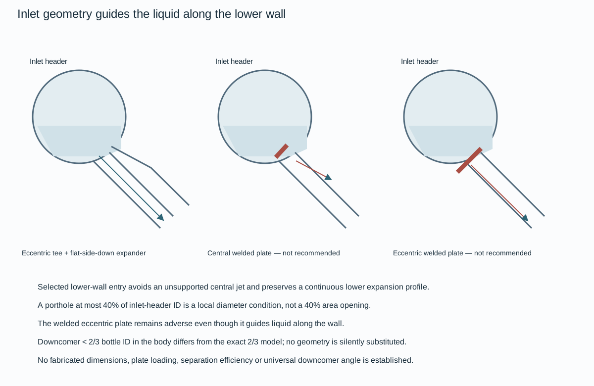
Figure 12.7. Qualitative lower-side eccentric tee and flat-side-down expander under the adopted construction method, alongside centrally and eccentrically located welded splitter plates. Both welded-plate alternatives are not recommended in the depicted method. Wall guidance in the eccentric plate does not reverse that disposition. The view supplies no plate loading, dimensions, fabricated specification or validated separation result.
The selected construction uses an eccentric tee on the inlet manifold followed by an expander with its flat side down, replacing the internal welded constrictor approach. Downstream expansion promotes segregation while the lower path remains continuous. The related bottle-entry flat-side-down expander avoids a lower-slope discontinuity that can disturb developing stratified liquid flow. A flat-side-up example and flat-side-down examples are distinct geometries. They cannot be exchanged merely because their nominal end sizes agree.
The local method favors a downcomer inclined at approximately 45° to promote stratification, rather than treating every vertical downcomer as equivalent. It separately describes an existing downcomer diameter less than two-thirds of bottle diameter, while a later model uses an exact two-thirds geometry.
- Preserve the adopted model's assumptions and actual inside bores.
- Do not silently replace the inequality by the model value.
- Do not convert a model dimension into a universal fabrication rule.
Separation and storage slopes also remain distinct. The general dual-slope method recommends a 1% minimum for storage/secondary sections and a separation-section maximum near 2.5%. A particular slow-flow storage concept uses 0.4%. Another drawing shows a 3% separation section with a 1% storage section. The slow-flow operating qualification and the difference between the drawn 3% example and the general recommendation remain attached to those cases.
No single combined slope prescription is inferred.
- Determine the actual geometry with the selected separation, filling/choking and usable-volume evaluations, then account for support height and plot consequences.
Distinguish the deposition mechanism experiment from the working panels
Gravity, turbulent diffusion and impingement in an entry bend can contribute differently as droplet size changes. The mechanism comparison below comes from a configured numerical experiment, not the six-panel design lookup. It uses gas velocity 3 m/s, a 45° downcomer and a printed diameter ratio of 0.75. The surrounding dimensions are a 1.22-m bottle and 0.9-m downcomer. Its assumed maximum droplet size is described as 500 μm, while the plotted size axis reaches 600 μm.
- Preserve the stated assumption and displayed axis separately rather than silently replace either with the later 750/1000-μm working-panel cases.
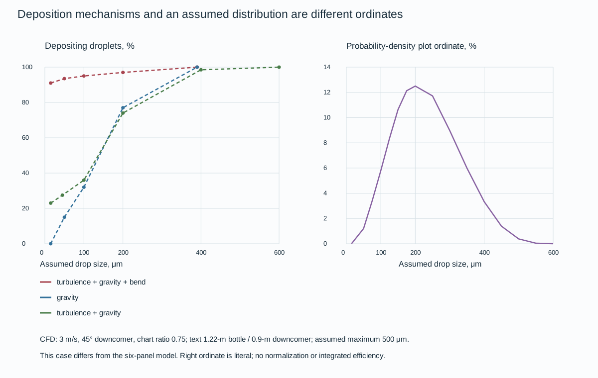
Figure 12.8. Original graphical recovery of the configured deposition comparison: gravity; turbulence plus gravity; and turbulence, gravity and bend. The assumed droplet-distribution shape uses its own right-axis ordinate in the original and is separated into a second native panel to keep the quantities distinct. The recovered deposition allowance is estimated ±2 percentage points; the distribution-ordinate allowance is estimated ±0.5 percentage point. These are author reading estimates, not simulation accuracy bounds.
At an assumed size near 100 μm, the graphical gravity result is about 32% depositing, turbulence plus gravity about 36%, and the combined bend result about 95%. Near 200 μm, the gravity and turbulence/gravity readings are about 77% and 74%, while the combined bend curve is about 97%. These local readings show the strong configured influence of the entry bend without claiming that turbulence always improves every point. Larger droplets increasingly respond to gravity. Smaller droplets can deposit by following turbulent fluctuations toward walls.
The mechanism depends on the actual flow and entry geometry.
The experiment does not supply all fluid-property/temperature inputs or validate scale-up. The plotted probability-density percentage lacks an established measure and normalization here; do not integrate or weight it to infer aggregate efficiency.
The experiment data and conditions keep the mechanism results distinct from the later model's gas/liquid densities, viscosity, 2/3 ratios and duty limit.
A branch can take different shares of gas and liquid
A two-phase branch does not necessarily receive equal fractions of the two phases. Orientation, flow regime, superficial velocities and geometry affect which phase enters it. A downward arm can receive much of the liquid while gas continues through the main. An upward arm can take gas with little liquid until the selected flow condition changes.
- Use the following experiments to understand that separation mechanism, retaining their scale and conditions.
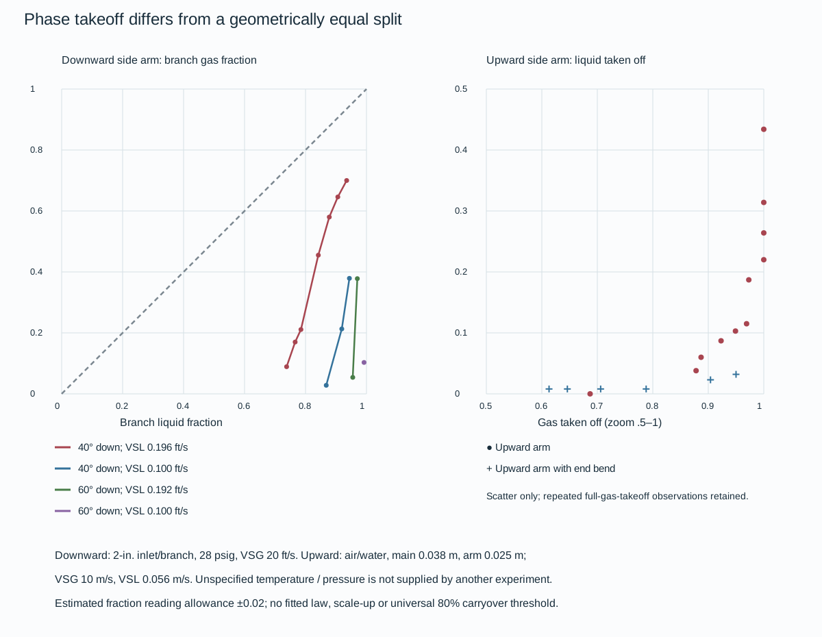
Figure 12.9. Left: four original series for 40° and 60° downward arms, with 2-inch inlet/branch diameters, 28 psig pressure and superficial gas velocity 20 ft/s. The series retain their separate superficial liquid velocities of 0.196, 0.100, 0.192 and 0.100 ft/s. The diagonal is an equal-phase-fraction reference, not a fitted experimental line. Right: unfitted air/water observations for a vertical upward arm and an upward arm with a bend at the end of the main. These use main diameter 0.038 m, arm diameter 0.025 m, superficial gas velocity 10 m/s and liquid velocity 0.056 m/s. The right horizontal axis is zoomed to 0.5–1.0. Estimated reading allowance is ±0.02 in phase fractions; the single-marker and repeated-abscissa observations remain intact.
For the 40° downward arm at liquid superficial velocity 0.196 ft/s, one recovered point near 0.84 of the entering liquid gives about 0.46 of the gas entering the branch. Equal geometric flow division would miss that phase difference. The other liquid-velocity and angle series are not an interpolation grid: the 60°/0.100-ft/s series contains only one plotted observation. Connecting the source's joined multi-point traces is useful for visual comparison within each series, but no new line fit, unobserved operating domain or experiment-scale conversion is supplied.
For the upward-arm air/water experiment, one point near 0.95 gas takeoff has approximately 0.10 liquid takeoff in the simple-arm series, while the end-bend series remains near 0.03 liquid takeoff at similar gas share. Several simple-arm points at full gas takeoff range from about 0.22 to 0.43 liquid takeoff. Collapsing them into one invented curve would erase the observations. Near-zero markers are retained as approximate readings rather than forced to exact zero. The experiment does not state the pressure and temperature needed to transplant its properties to another service.
The local account associates good upward separation with gas takeoff below roughly 80% and describes a selected 70/30 two-riser arrangement using that behavior. The observation and that implementation are not a universal carryover threshold or automatic design split. Larger-scale bottles, condensate properties, mist size and actual riser restrictions need the applicable evaluation.
- Compare the operating state and geometry, including partial availability, before making the phase-split evidence a design input.
Symmetry belongs to the gas-outlet pressure path
Gas leaving the primary bottles passes through risers and a collection header to the outlet. An undersized or unbalanced outlet path can impose different gas pressures on bottles. Liquid levels can then shift by manometer action, with bottles nearer the outlet rising relative to the others. A layout that balances this path addresses a different mechanism from adding a gas equalizer between storage bottles.
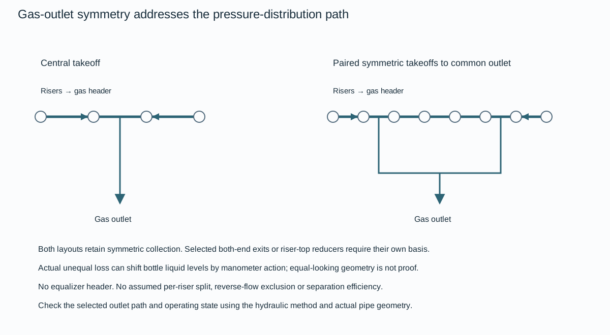
Figure 12.10. Two qualitative collection configurations: a symmetric central header takeoff and paired symmetric takeoffs collected into a common central outlet. Circles represent riser connections. The arrows show intended collection directions; they do not establish measured or calculated flow shares. No equalizer header is added.
The adopted gas-outlet method also considers gas exiting both ends of a header or selected reducers at riser tops to balance distribution. These arrangements require their actual pipe, resistance and operating basis. A two-riser approach can depend on a deliberately sized gas split and a separately evaluated carryover condition. The symmetric drawing does not create that split, exclude reverse flow or justify adding arbitrary extra risers.
- Preserve the intended primary-bottle gas escape and liquid collection paths, then verify pressure distribution and the heavily loaded arrival state under the hydraulic method.
The liquid header has a separate elevation duty. Under the adopted drainage method, locate it below the bottles' lower ends to avoid gas carry-under during liquid removal.
- Keep low-point drains, distributed liquid outlets and accessible header ends for sludge removal and cleaning.
A diameter reduction shown workable for one model remains bounded by dirt blockage and cleaning access. Outlet geometry cannot establish either useful storage volume or gas/liquid separation efficiency without the corresponding calculations and operating-state checks.
During rapid liquid receipt, descending liquid must leave a path for displaced gas. At a configured intake rate, stratified flow can no longer be maintained and the bottle becomes choked with liquid. Bottle slope affects that onset, but also the height and storage geometry. A steeper bottle is therefore not automatically a higher-capacity or better-separating choice.
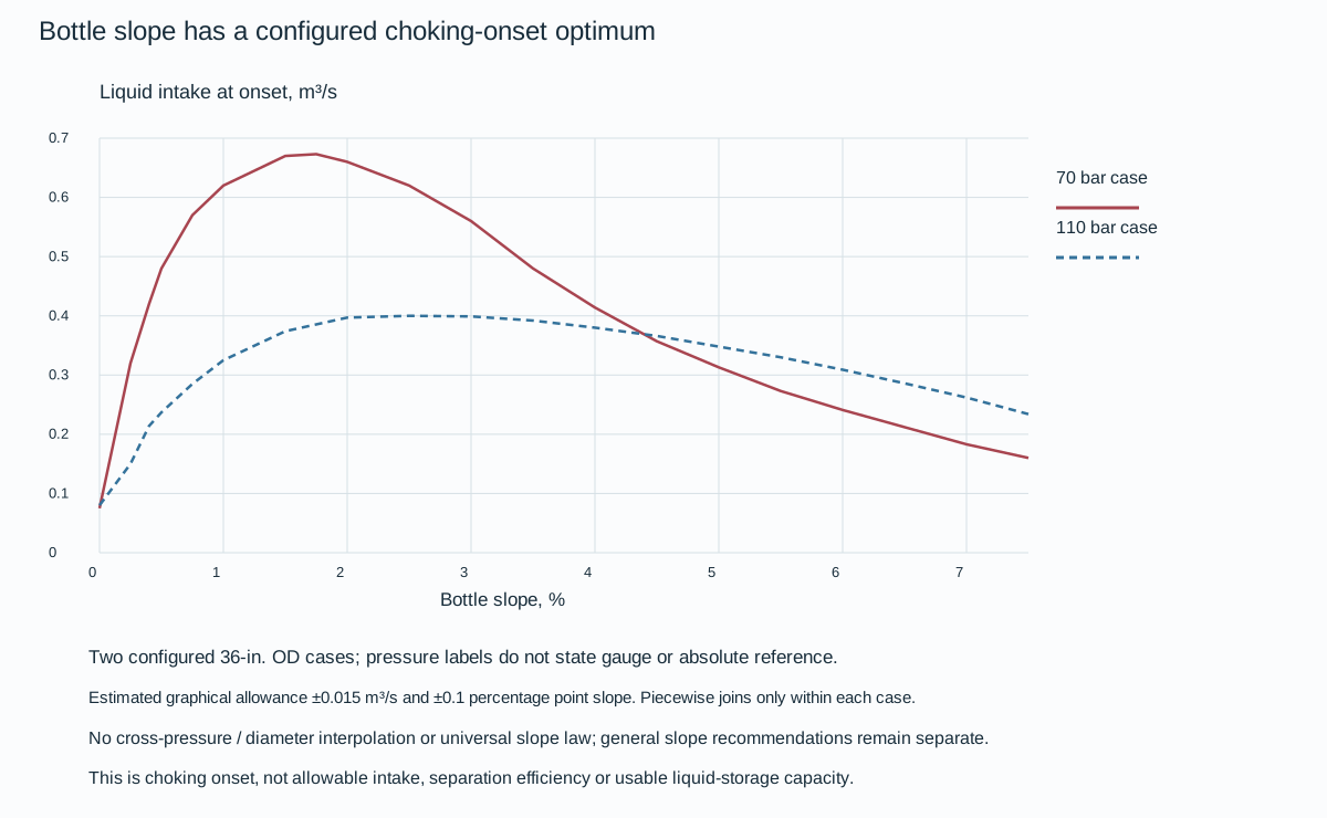
Figure 12.11. Approximate original-curve recovery for two configured 36-inch outside-diameter bottle cases labeled 70 and 110 bar. The pressure labels do not state gauge or absolute reference. The plotted intake rate is choking onset in m³/s, with bottle slope in percent. Estimated graphical reading allowances are ±0.015 m³/s and ±0.1 percentage point of slope. Saved case data and model limits preserve the configurations; no cross-pressure or diameter scaling is supplied.
In the 70-bar configured case, the recovered intake at a slope near 1.5% is about 0.67 m³/s and the plotted peak is near 1.7–1.8%. At 3% the curve falls to about 0.56 m³/s, and at 5% to about 0.31 m³/s. The 110-bar case peaks more broadly near 2.5% at about 0.40 m³/s. Its 0.4% marked operating slope gives about 0.21 m³/s. These comparisons establish the chart's configured trend, including the descending side of each curve, rather than a universal monotonic benefit from slope.
The underlying account describes a Kelvin–Helmholtz-based model supported by simulation experiments and reports a 70-bar case prediction near 0.67 m³/s compared with approximately 0.70 m³/s measured in practice.
- Keep predicted and reported measured quantities distinct.
The complete fluid properties, geometry and solver inputs for generating another case are not supplied by these two traces. No pressure-reference correction, pressure interpolation or diameter-independent law is invented from their difference. The 36-inch OD label is not the inside diameter for a volume or stress calculation.
Straight joining between saved slope samples can compare positions within the same configured case. It does not create an allowable operating intake, a separation-efficiency result or usable liquid capacity. The chart's domain up to 7.5% also does not replace the separate general minimum-storage and recommended maximum-separation slopes in the adopted geometric method.
- Resolve the applicable arrival state, no-transfer/maldistribution loading, fluid/geometry basis and operating limits before choosing a bottle slope.
Then carry the actual fall and buried or supported configuration into storage, stress and construction evaluation.
Calculate usable storage from the liquid surface and riser geometry
The liquid imbalance calculated above must fit within usable bottle geometry. Under the multiple-pipe method developed here, maximum primary-bottle liquid level is at the intersection of the lowest gas-riser centerline with the lower inner wall of the bottle. The sloping upstream region is partly filled at that horizontal liquid level. Crediting its entire circular cylinder volume would count space that must remain available for gas communication.
For the method's depicted single- or dual-slope geometry, the partly filled contribution is
In this equation, is bottle internal diameter in m. is the angle of the bottle beneath the riser to horizontal, and is in m³. For its dual-slope construction the riser reference is from the slope intersection, where is the steeper section's angle. These expressions describe the supplied geometry, not every arbitrary bottle profile or an additional process buffer.
Use the slope actually beneath the riser for volume. Calculate fully filled portions and other bottles separately, then compare total useful inventory with the arrival/removal/buffer case. The separate dual-slope riser-distance convention does not transfer a volume from one slope to another.
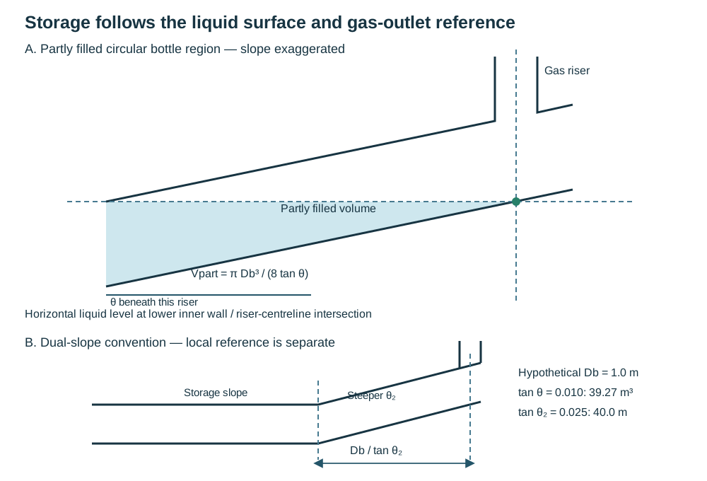
Figure 12.12. Authored schematic of the partly filled primary-bottle region. Slope is exaggerated, the liquid level is horizontal, and its reference reaches the lower inner wall at the gas-riser centerline. A separate dual-slope panel marks the local riser-distance convention. Structured geometry and calculations distinguish the partly filled volume from total catcher inventory. Secondary-bottle free surfaces must retain their own gas path; this sketch is not a fabricated section.
Secondary storage must be arranged so that its full-condition free surface is not wholly within its riser. Different slopes and lengths can change that position. A nominal storage volume that fills the wrong gas-outlet region can lose the phase-separation function just when the arrival demands it.
Check the gas escape path in its heavily loaded pigging state
Under the adopted riser method, define the load factor
In these equations, gas and liquid densities use kg/m³. is riser internal diameter in m. is risers per primary bottle, and is primary-bottle count. and are in m/s. is the method's pipeline gas-flow quantity in m³/s on the actual condition basis corresponding to the highest pigging/sphering velocity, rather than an unconverted standard flow or an assumed maximum normal throughput.
Its check uses m/s to settle droplets larger than 2 mm in the gas riser.
- Apply it to the bottle receiving 1.2 times equal share during pig/sphere arrival, with no liquid transfer from that bottle to other bottles.
Crediting transfer reduces the gas-escape demand and changes the prescribed case. This coarse-drop riser check does not establish the primary section's much finer mist separation.
Under this method the riser height is at least the lesser of five riser diameters and 5 m:
.
Two risers can introduce gas-flow imbalance: the arrangement discussed by the method throttles the second to about 20–30% of total gas under its own conditions. A maintenance state with part of the catcher isolated cannot inherit full-unit pigging capacity. Its no-sphering restriction remains consequential.
Check the droplet regime before turning settling time into length
A uniform-droplet calculation explains the dependence on size, density and viscosity. It is a limited model. The developed separation method instead prefers a droplet-size distribution with turbulent deposition, inlet expansion and the gas-riser junction represented. For a small droplet in the supplied Stokes regime,
In these expressions, is droplet diameter in m, and is gas dynamic viscosity in Pa·s. is in m/s², and is in m/s. The density definitions above remain.
- Compute the velocity, then verify its regime.
The supplied swarm relationship is , followed by . is dimensionless liquid holdup fraction. The method gives ranging from 4.65 to 2.39 over , without a complete interpolation law. A droplet distribution with turbulence/wall deposition cannot be replaced by one uniform small size or an unjustified exponent selection.
At higher Reynolds numbers the drag relation and velocity must be solved on their applicable basis. The available large-Re expression in this treatment lacks a dimensionally valid velocity basis. Dimensional analysis identifies the deficiency but does not qualify a replacement drag law. No high-Re velocity prediction is made from it here. This limitation does not invalidate the low-Re method or justify skipping the developed deposition-model path.
For the developed deposition path, match density, maximum droplet size, inlet/bottle geometry and no-re-entrainment conditions to the complete working-panel basis below before reading .
A representative coarse read at 60 kg/m³ gas density, 1000 µm maximum drop size, 2.0 m/s bottle gas velocity and the 99.5% curve is about .
- Carry an illustrative reading band of 8–12 for this graphical observation, rather than treat it as precise tabulated data.
The structured separation method preserves model conditions, quantities and uncertainty. The 40/60/80-density graphs do not consistently support monotonic higher-density substitution.
- Preserve that limitation when the actual density is not represented.
- Establish the applicable model or graph disposition instead of choosing a supposedly stricter curve.
If the required length will not fit, revise primary-bottle count or diameter and repeat the flow/geometry evaluation.
Use the separation chart only with its complete model gates
The developed deposition model provides six working panels rather than one general length curve.
- Select the represented gas density, maximum droplet size and target efficiency together, after confirming the inlet and bottle geometry.
A line labeled 99.5% describes the model's predicted separation at its conditions. It is not a measured efficiency certificate for an installed catcher.
The common model basis is liquid density 600 kg/m³, liquid-to-gas volume ratio 0.05 and gas dynamic viscosity approximately 0.000012 Pa·s. Gas density is 40, 60 or 80 kg/m³. The panels separately use maximum droplet sizes 750 and 1000 μm in a Kataoka-labeled distribution. The geometry is a 45° downcomer followed by a 1.5D bend and flat-side-down expander. Both downcomer/primary-bottle and gas-riser/primary-bottle inside-diameter ratios are 2/3.
The model assumes that liquid, once deposited, does not re-entrain. All these gates travel with the chart. Selecting density alone does not establish compatibility.

Figure 12.13. Approximate original-curve recovery for six panels, with efficiency families 80%, 90%, 93%, 96%, 99% and 99.5%. The recovered velocity spans and the top clipping at remain explicit. Shading above 2 m/s identifies plotted comparison space outside the stated separation-section duty limit; the plot's 4-m/s axis does not authorize that duty. The lower-efficiency curves permit comparison but do not satisfy the selected method's requirement for better than 99%. Recovered panel data and all model gates and the native drawing implementation preserve the curves without a fitted external equation.
For a represented panel and efficiency, read gas velocity on the horizontal axis and on the selected curve. Between saved samples, a straight joining of against velocity supplies an approximate graphical lookup.
- Do not interpolate between efficiency families, densities or maximum droplet cases, and do not extend a curve beyond its saved span.
The author-estimated reading allowance is the greater of ±0.5 in or ±5%, with ±0.03 m/s on velocity. This is graphical resolution, not an efficiency confidence interval or a design margin. A steep upper curve can make velocity uncertainty consequential, particularly near the clipped top of the chart.
Once the model basis is adopted and matched, convert the ratio using the actual primary-bottle inside diameter:
In this equation, and are in meters, and is dimensionless. The separation length runs from the model's bottle-entry reference to the first exit riser. It is distinct from the full storage length.
- Do not insert a 36-inch outside diameter or a nominal pipe label as though it were the inside diameter.
The bounded lookup implementation reproduces the saved-data interpolation and teaching length conversion. Its duty mode rejects velocity above 2 m/s and efficiency at or below 99%. Its comparison mode does not turn those plotted values into permissions.
Droplet-size selection materially affects length: at 60 kg/m³, 1.5 m/s and 99.5%, the recovered 1000-μm panel gives approximately , versus 8.87 for 750 μm. These are model readings, not project lengths or actual efficiency evidence. At 1000 μm and 1.5 m/s the 40-, 60- and 80-kg/m³ panels give approximately 8.92, 6.25 and 12.49. Their nonmonotonic order conflicts with the procedure’s suggested higher-density substitution; preserve that conflict.
No off-density selection, interpolation or presumed conservative curve is supplied here.
The 1000-μm choice reflects the stated empirical droplet basis for the adopted configuration. The smaller 750-μm assumption was suggested for vertical or strongly disturbing entries where re-entrainment could occur. Choosing that panel does not prove that a geometry violating the 45°/bend/expansion/no-re-entrainment model has become valid.
- Establish the applicable model or specific disposition before applying it to a different inlet.
If the required length cannot fit the plot, reconsider bottle count, diameter and flow, then repeat the actual model comparison rather than crop the separation section to the available space.
Burial moves the transition, support and inspection questions
A sloping catcher body can lie below naturally sloping ground, inside a constructed mound on a level plot, or transition into an outlet access pit. These choices preserve different exposed lengths, support conditions and work spaces.
- Coordinate bottle gradient and liquid-header elevation with the ground model before choosing an earth profile.
Hiding a long pipe beneath fill does not remove its thermal movement, testing weight or differential settlement.
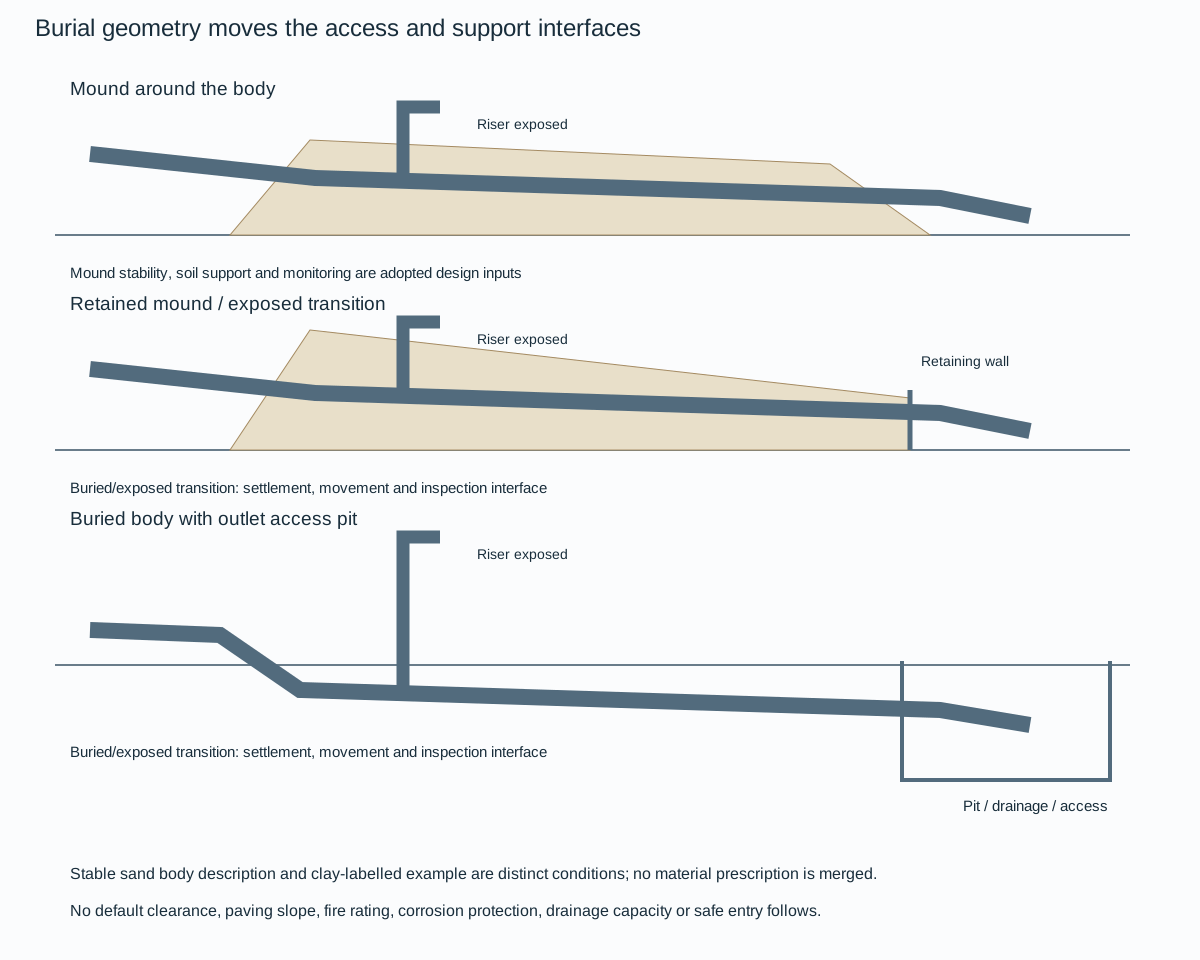
Figure 12.14. Qualitative whole-mound, retained-mound/exposed-transition and buried-body/access-pit alternatives. The original-grade reference, exposed riser and buried/exposed pipe transition are kept visible. Dimensions, paving slopes and transit details are not transferred as universal clearances, fire protection or settlement allowances. This is an interface comparison, not a foundation or safe-entry design.
The body description uses a stable sand mound, while a drawn mound example is labeled clay. Those are different source examples rather than a combined material prescription.
- Select mound stability, foundation preparation, drainage and pipe support for the actual ground and load basis.
A retaining wall or pit can reduce mound height while concentrating an exposed/buried transition at a wall penetration. The illustrated rubber transit detail is an example requiring its adopted movement and sealing basis. It does not qualify a generic settlement accommodation or fire barrier.
- Evaluate pressure, thermal expansion, slug or surge passage, support reactions, environmental loads and test contents in the actual supported or buried state.
Differential settlement of the catcher and adjoining structures can deform the exposed/buried transition even when each foundation appears locally adequate. The wall or pit must leave the pipe's intended load and movement path rather than impose an accidental restraint. Stress evaluation and support/restraint design provide the coupled mechanical account.
- Plan condition monitoring for the buried sections during design so routine assessment need not depend on unplanned excavation.
Header-end access remains useful for inspection and sludge removal. Ensure its removal and working space remains available beyond the mound or within the selected pit. Drainage, contaminant collection and access for maintenance belong to the real arrangement. A drawn pit provides no safe-entry condition or drainage capacity, and burial alone does not demonstrate the fire-resistance or escalation outcome claimed for a particular site.
- Evaluate those functions under the adopted hazard, corrosion and intervention basis before relying on the earth cover.
Establish the installed pipeline through construction and precommissioning
Construction changes the configuration before the line begins its intended service. Stringing, bending, welding, lowering into the trench and backfilling create temporary support and deformation states. Onshore working strips need room for the construction spread and reinstatement of topsoil, drainage and other preserved features. Swamp flotation or push-pull installation offers different equipment and environmental consequences. Offshore S-lay, J-lay, reeling or tow methods create other curvature, tension, contact and vessel-motion histories.
Select and analyze the actual method rather than represent all construction by an empty version of the operating model.
Prevent debris and muddy water entering open pipe, control welding/examination in the actual field conditions and restore field-joint coating.
Before acceptance, establish the installed bore condition as well as the pressure boundary. A gauge-plate or caliper pig can identify dents/buckles that a pressure test is not intended to locate. Test and precommissioning tools also need a route and a receiver that can handle them.
For a project specifically adopting one pipeline hydrotest procedure, strength testing is followed by a leak-tightness assessment of portions that cannot be inspected for leaks during the strength test. The two phases use different pressure/temperature control logic. That procedure uses a strength basis of at least 90% specified minimum yield stress at minimum wall thickness. Its subsequent leak phase starts at 80% of strength-test pressure and permits temperature-driven fluctuation without adding or removing water. A separately conditioned combined test is another option. These are scoped pipeline test criteria, not numbers to impose on plant piping or special materials.
System testing develops boundaries, stored energy and restoration.
- Retain the applicable pipeline procedure rather than choose a larger number from another basis.
Route elevation makes test pressure vary along the line, and stronger/thicker sections may need a separately established test before incorporation. Temperature changes must be understood when interpreting pressure change.
- Treat tie-in welds that are outside the hydrotest boundary by the required additional examination.
After water testing, cleaning, dewatering, drying or inerting follow the service and precommissioning basis. Passing the pressure test does not establish a dry gas or a clean oxygen condition.
Records retain the actual installation: route/burial survey, pipe joint/tally identity, material/wall/coating, jointing/examination and test evidence, changes and their reasons, nonconformances and repairs. Handover also preserves operating limits, special states, pigging purpose and adjustment criteria, route/corrosion/valve monitoring, access and contingency arrangements. Technical records explains continuity. The pipeline's installed location and geometry must remain linked to those decisions.
Make offshore facility piping maintainable in its actual space
Offshore facility piping and the transmission/riser interface have related but distinct duties. Congestion, restricted crane/support access, harsh external corrosion and costly intervention strengthen the case for deliberate layout and onshore fabrication. They also make a completely prefabricated fit without adjustment difficult.
- Preserve an appropriate field-fit allowance and verification of the actual structure/equipment interfaces, rather than force a spool into an assumed geometry.
Routing overhead, in central racks or beneath decks can preserve equipment access, while deck-level lines can obstruct operation and removal. The chosen position must still allow inspection, lifting and corrosion maintenance.
- Minimize unnecessary hydrocarbon connections over water.
- Retain removable sections where equipment servicing or modification actually requires them.
A facility maintenance spool and a seabed transmission tie-in need different joint strategies. A plant practice using periodic flanged removal points and a pipeline practice preferring welded tie-ins need not become one universal connection rule.
Wellhead flowlines can carry sand and have concentrated erosion locations. A selected target-tee or replaceable spool arrangement addresses access to an expected wear location, rather than making the whole line immune to erosion. Small connections susceptible to vibration or mechanical damage need their specified joining/bracing treatment. Closed vessel/instrument drainage retains hydrocarbon vapor, while deck-floor drainage needs the appropriate traps, slope, cleanouts and penetration arrangements. Connections and drain architecture carry the associated functions.
Corrosion at a support can arise from a wet crevice even with a suitable coating elsewhere. Support details must provide the required mechanical restraint and avoid moisture traps against the pipe, while permitting the selected removal/maintenance. Clearances between parallel surfaces and around penetrations need enough room for surface preparation and recoating. The detailed dimensions and material compatibility belong to the adopted arrangement. Rubber or another contact material is not automatically a suitable vibration, restraint and corrosion solution for every line.
The riser account here concerns rigid metallic piping, its clamps and the associated expansion/tie-in arrangement. Flexible and nonmetallic risers require separate design bases.
- Define the topside, jacket and pipeline/spool interfaces with their loads, movements and responsibilities.
A code break does not terminate mechanical influence: the structure can move a support, and the pipeline can expand into the riser even where component scope changes.
The topside interface includes piping layout, terminal/valve and pigging access, electrical isolation, supporting structure and overlap of analyses. The jacket interface supplies actual members, dimensions, deflection, support types, protection and installation provisions. The pipeline/spool interface supplies approach geometry, expansion, tie-in method and an analysis overlap that can carry the interaction continuously.
- Avoid a disconnected pair of models in which each assumes the other boundary is fixed.
Weight includes steel, contents, coatings, attachments, anodes, marine growth and buoyancy. Water absorption by weight coating can change it. Pressure and temperature create both direct demands and movement under restraint. Residual lay tension, curvature and seabed undulations can remain after installation. Pigging/slugging, surge, waves/currents, wind and relevant seismic/ice conditions add other demands.
A modeled force list is not yet an evaluated combination: environmental direction, phase and the system configuration can make different locations govern under different cases.
Hydrodynamic evaluation must match water depth, wave/current theory and profiles, appropriate drag/lift/inertia coefficients and combined directions/phases. Shielding or amplification near jacket members changes the local flow.
- Distinguish the environmental descriptors required by the adopted analysis.
A maximum-wave condition is not replaced casually by a significant-wave height. Vortex excitation and fatigue are different checks from static yielding. Mechanical analysis supplies their broader interpretation, with the actual riser environment retained as input.
Establish the support and installation state before evaluating it
A guide clamp controls transverse motion while retaining the intended axial movement/rotation. A deadweight clamp carries the selected weight path, with its downward axial restraint and other freedoms determined by its detail. An anchor restrains movement and rotation in the specified directions. Those functions cannot be assigned interchangeably because all three are called clamps.
- Select them from the required riser movement and reactions and carry the loads into the supporting structure.
Installation, hydrotest and operation create distinct states. Handling, load-out, transport, upending or retrofit can change gravity direction, support contact, temporary restraint and vessel-motion loading. Hydrotesting adds contents and pressure under its actual support/environmental condition. Operation adds thermal, residual and cyclic/environmental combinations. A temporary knee brace can reduce installation stress yet increase operational restraint.
Under the scoped installation arrangement it is removed completely after installation. The model and records must reflect that restoration.
Retrofit clamp alignment depends on as-built accuracy, diver measurements, fabrication/handling change, closure and adjustment tolerances. Provision for adjustment can avoid pulling the installed riser into an assumed location and creating unintended stress.
- Examine access for bolt tensioning and a design that limits stress concentrations under cyclic load.
The support's own weight and environment join the reactions transmitted by the riser. Support function explains the general distinction. The riser-specific state and adjustment must be established here.
Pipeline expansion can be restrained away from the platform or absorbed through a flexible geometry. Rock placement, trench/backfill, added submerged weight or an anchor change resistance. A spool/loop or selected flexibility changes the displacement accommodation. Lower seabed friction can increase movement reaching the riser, whereas greater friction can increase a pull-in demand. The “conservative” coefficient therefore depends on the question.
Settlement into another soil layer or scour can change resistance over time.
Preserve the range and assumptions rather than assign one friction value to every state.
Protect above-water, splash-zone and submerged supports according to their actual exposure and electrical relation.
A clamp can shield cathodic protection or create a difficult inspection location.
- Avoid a splash-zone support where practicable under the riser basis, and evaluate unavoidable locations for corrosion and access.
Protection must preserve the intended movement as well as integrity. A liner that grips an intended guide can create a different restraint.
Similar clamp outlines can represent different installed freedoms. Figure 12.15 compares three riser-to-jacket load paths and a separate retrofit adjustment arrangement. The guide has a split hinged clamp connected to a jacket sleeve through a structural member. Its lined inside diameter permits axial travel without significant restraint while contact limits movement perpendicular to the riser. The lining, coating and closure setting must preserve that function.
Tightening it into a gripping clamp changes the modeled boundary.
The deadweight detail adds a sleeve welded to the riser and a projecting flange that bears on the support clamp. Downward weight enters the sleeve/flange, the bearing face and the jacket connection. This one-sided bearing is different from a connection preventing axial movement in both directions. Rotation and other axial freedom depend on the detailed arrangement, including whether the bearing lifts clear. A device called a deadweight clamp must not be assigned a full anchor merely because its flange is labeled an anchor flange.
The illustrated anchor instead transfers reaction through a doubler attached to the riser by circumferential welds, into the connecting member and jacket. Its intended function is restraint in all directions, including torque, under the selected riser basis. That intention requires actual connection stiffness and capacity. An integral anchor flange welded into the riser string is another construction route with its own fabrication and pressure-component basis. It is not an interchangeable external doubler.
Material, parent wall, attachment welds, examination and fatigue assessment remain local to the selected route.

Figure 12.15. Three separate installed support functions and an erection-state adjustment schematic. Guide travel arrows describe intended operating freedoms; adjustment arrows describe alignment before the final connection/closure is established. No load rating, spacing or adjustment dimension is encoded. Structured clamp and state constraints retain the distinction.
Retrofit adjustment accommodates errors in as-built geometry, diver measurements, clamp position, closure, fabrication and handling. The selected arrangement permits adjustment at the riser clamp and connecting stub, and relative angular alignment at the jacket attachment. These are installation provisions for a stress-free fit, not unlimited travel after assembly. The local procedure's 250-mm adjustment allowance belongs to that installation basis.
- Establish the available axes and tolerance stack for the actual clamp, then record the closed, tensioned and restored operational configuration.
A temporary knee brace that was necessary during installation may need complete removal to restore the analyzed freedom.
Bolt tensioning needs sufficient bolt length and physical access for its tooling. Pre-tension must follow the qualified joint design.
- Include hydrotest contents, support weight, environmental load and the riser's transmitted reactions in the support/structure assessment.
Cyclic loading makes local concentration and bolt stress changes consequential. The drawing's contact topology cannot supply the reaction, preload, fatigue resistance or jacket capacity.
For the selected lined-guide procedure, ribbed polychloroprene lining is vulcanized to the guide, and coating protection at the travel interface may include specified external metal sheeting.
- Preserve clearance and travel through the entire coating/liner stack.
Ribbing also addresses shielding of cathodic protection. Retrofit supports require the selected electrical-continuity route. Above-water, splash-zone and submerged locations have different coating, corrosion-allowance and cathodic-protection conditions.
- Avoid splash-zone supports where practicable under that basis, and retain inspection access where they are unavoidable.
Choose a marine attachment with its moisture and removal interfaces
A marine support can hide deterioration at the same contact through which it carries the pipe. Figure 12.16 separates fixed attachment from removable contact rather than claiming either eliminates corrosion. In the fixed examples, seal-welded plates or a doubler and stand-off carry reactions to the structural member. The doubler detail seals its ends and explicitly avoids penetrating the flow-line wall. A saddle alternative has its own vent-hole sealing detail.
These features have distinct fabrication and inspection routes. A seal weld at one interface does not justify sealing or drilling another.

Figure 12.16. Qualitative fixed doubler/stand-off and removable split-clamp alternatives. The fixed load path includes the parent wall and attachment weld; removable contact needs its own liner, fastener and release/load-support procedure. The drawing does not certify corrosion immunity or hardware capacity.
The removable examples include a sleeved U-bolt with support pad and a split clamp on a stand-off. Their sleeves/liners change contact and can reduce abrasion or vibration, but retained moisture, damaged coating or an unsuitable fit can still cause local damage.
- Select their material and coating compatibility, inspectability and actual contact pressure.
In the split-clamp family, the illustrated neoprene insulation belongs only to its insulated variant. The bare and coated-pipe variants cannot inherit that liner by appearance. Its slots belong in the bottom clamp only. Coating, clamp thickness and fastener selection are part of the actual detail rather than dimensions inferred from this panel.
Fixed details reduce the need to release a pipe-to-support joint during routine work but retain welded pressure-wall interfaces. A removable arrangement can permit equipment servicing or pipe changeout while requiring a safe load path before fasteners are loosened. A pipe can remain supported in normal service and become unstable during partial removal.
- Plan temporary support, tool access, isolation and restoration under the applicable work procedure.
The drawing itself grants no permission to release a clamp or repair a live attachment. Historic plating, galvanizing or paint choices remain subject to the adopted material/service restrictions.
A deck collar and the riser clearance serve separate purposes
Figure 12.17 shows a raised collar attached to a deck around a riser. The collar-to-deck joint and the free clearance to the riser are separate interfaces. The space around the riser provides access for surface preparation and recoating and must also remain compatible with movement. A collar is not attached to the riser in this example. It does not carry riser weight or establish a pressure, fire-rated or watertight seal.

Figure 12.17. Conceptual penetration section. The raised collar is attached to the deck; clearance remains between collar and riser. Actual coating/tool access, movement, deck and collar construction are project inputs. The local source clearance, collar height and schedule are not encoded as universal dimensions.
Access has to be usable after installation.
- Account for adjacent pipes, bracing, insulation and the reach of the selected preparation/coating tools.
The local 2.5-in clearance and 4-in collar rise are detail examples rather than general offshore minima. A visible gap is not proof of tool access, and filling it with a later seal changes both access and movement.
- Keep the deck penetration, riser support and any separately required barrier/sealing function distinct in the drawings and inspection record.
Structured interface data connect these construction, operating and maintenance states without assigning an unverified capacity.
Give ovalization its defined denominator
Flattening under manufacture, external pressure or bending changes the riser section and can contribute to buckling or collapse. A reported percentage is useful only with its normalization. One rigid-riser method defines
This expression uses maximum and minimum outside diameters in the same unit, with a local 2.5% limit. A percentage normalized by mean diameter is twice this quantity and cannot be compared directly with that limit.
The riser method data retains this convention. Meeting that shape criterion alone establishes neither external-collapse resistance, fatigue life nor suitability for a plastic pull-in state.
A J-tube creates an installation path and an annular environment
A J-tube must pass the riser and its pull-head through the actual bends while carrying the pull-in contact loads. Larger radii, smaller bend angles and fewer bends can reduce friction and imposed bending. Under one adopted rigid-steel pull-in criterion, routing uses typical bend radii near 100 pipe diameters and excludes radii below 50. The J-tube internal diameter is at least twice the riser diameter. These are local screening/design criteria, not a substitute for a pull-head passage and strain/collapse assessment.
- Analyze the pull-in step by step from bellmouth entry to the final position.
- Include back-tension, elastoplastic bending, riser/cable contact friction, radial bend loads, potential bellmouth or J-tube jamming and the load before the winch stops.
The pull-head must transmit tension without damaging the riser and must fit through the bend. A scaled geometry check can expose a jamming configuration before a load calculation is trusted. The winch, cable, J-tube and supports must share one evaluated installation basis.
The installed annulus creates another service environment. A selected seal excludes seawater and retains inhibited water or another compatible medium. Its restraint on the riser, flushing behavior and ability to retain the medium need assessment as well as nominal sealing.
- Provide the required sample/maintenance route.
The bellmouth can have different installation and operational reactions, and protection of the J-tube exterior remains a marine corrosion problem. A successful pull-in is not proof that the annulus will remain noncorrosive or that its seal permits the required operating movement.
Select the seal for pressure direction, movement and replacement
The J-tube annular seal separates its retained medium from the sea. Its differential pressure depends on both fluid columns and their pressure references, not solely on water depth. Under a hydrostatic seal method,
In this equation, is inside-minus-outside differential pressure at the seal. is gauge pressure at the top of the J-tube fluid. is its density, and is seawater density, both in kg/m³. is height from the seal to the top of the retained fluid. is seal depth below mean sea level, both in m.
With in m/s² the result is Pa. The simple balance assumes hydrostatic columns, consistent atmospheric gauge reference and stated densities. Wave effects, temperature/density variation and gas compressibility need their actual treatment.
Changing retained medium can reverse seal-demand direction and magnitude. Evaluate both actual fluid columns; a constant-density gas contrast is not a compressible-gas inventory model.
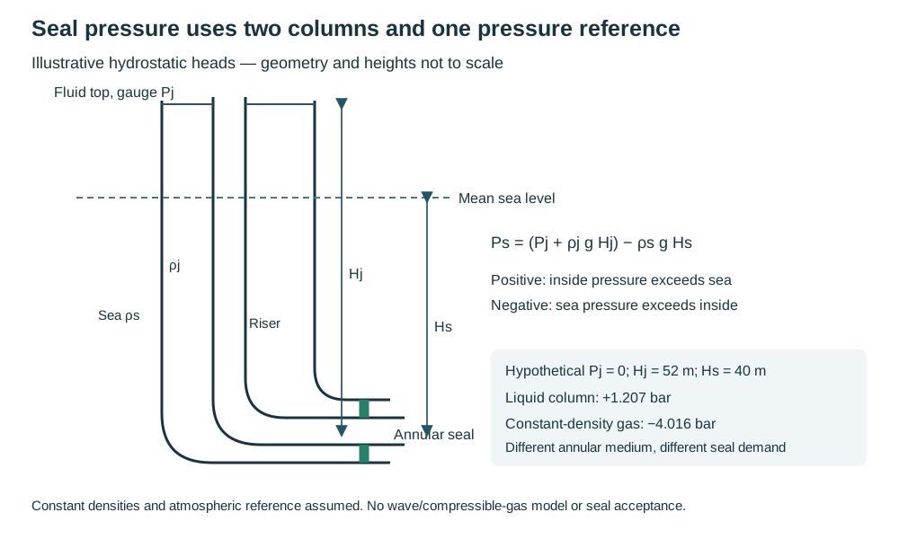
Figure 12.18. Authored hydrostatic reference sketch. Top-fluid gauge pressure and its seal-to-level height are distinct from seal depth below mean sea level. The inside-minus-outside sign permits either pressure direction. Structured seal data supplies the hypothetical liquid/gas comparison and scope; geometry is illustrative.
Seal construction also changes movement and repair. A conical elastomer seal relies on maintained contact/compression and limited motion. An inflated toroidal arrangement has a different shearing/slipping damage question. A boot installed for pull-in can suffer wear and may not be replaceable afterward. An integral diaphragm needs protection during pulling.
A zipped form can be installed later and replaced. A longer bellows sleeve can accommodate greater axial travel. An anchor-type seal keeps compression by preventing axial riser motion at the bellmouth, thereby transferring the thermal/restraint question into the system. These are functional alternatives, not interchangeable nominal seal ratings.
The described families include illustrative differential-pressure capabilities around 2 or 5 bar and millimeter-scale travel allowances. A family name does not qualify the actual calculated differential pressure.
- Establish the actual seal's permitted pressure direction, travel, attachment and retained compression, installation damage controls and replacement access.
- Combine those inputs with the riser's operating and shutdown movement/load assessment.
A sealed annulus that no longer permits its intended expansion has changed the mechanical system. A freely moving riser with an inaccessible worn seal has changed maintainability.
- Retain both consequences with the installed medium and sample/inspection plan.
Preserve inspection, replacement and the actual installed route
Inspection-tool geometry can govern bends, bore changes, valves and flanges early. For a riser arrangement specifically adopting the following intelligent-pig criterion, retain its nominal-diameter categories and minimum bend radii:
Table 12.2. Conditional intelligent-pig bend geometry.
| Nominal pipe diameter D in this criterion |
Minimum bend radius |
| D ≤ 100 mm |
10D |
| D from 150 to 250 mm |
5D |
| D ≥ 300 mm |
3D |
Unlisted sizes are not interpolated here. Tool-specific bore/bend requirements and the governing detail still apply; the structured interface data preserve this local scope.
- Aim for the internal continuity needed by the selected tool, with compatible valves and carefully evaluated transitions/pup pieces where diameters change.
Nominal pipe size alone does not describe the actual bore of a heavy-wall valve or fitting. Access along the riser for divers or remotely operated vehicles, support locations and the ability to replace a damaged riser can be as consequential as an analytical allowable. Where replacement is not feasible, a specifically assessed spare-riser provision may be appropriate. It does not justify leaving the working riser uninspectable.
After installation, record precise routing, clamp positions/types, tie-in geometry, support/structure interfaces, tolerances and any retained residual/temporary conditions.
- Update the actual configuration and the technical basis together.
A later repair, new pig type, added anode, changed fluid or rerouted topside branch can reopen affected geometry, weight, corrosion and movement assumptions. Condition assessment, intervention and records connect that work through the operating life. Useful routing preserves containment and function while leaving a credible way to find, inspect, maintain and change the installation.