Chapter 8 — Instrumentation, measurement and control systems
Use the adopted P&ID legend and instrument information to distinguish indication, recording, alarm and control. A local operating comparison may not satisfy accounting or protective requirements. The symbol does not establish range, accuracy, material, action or accessible mounting.
Keep ordinary regulation distinct from protection. A control valve can regulate a variable without providing an independent response to every hazardous departure. An alarm is not automatically a shutdown, and a valve-position indication is not proof of containment. Pressure and protective basis and the safety/service chapters establish those functions. This chapter explains measurement and control, while component behavior and physical connections explain the hardware interfaces supporting them.
Trace the complete sensing-to-action path
Begin with the physical quantity and its location. Pressure at a nozzle, metal skin temperature, fluid temperature inside a line and vessel liquid level are different measurements. A nearby connection may be convenient yet sense another condition from the one the function needs. Define where and in which operating states the information must be representative.
Then follow the path to the reading or action. Local gauges can provide direct observation at the equipment. A sensing element connected to a transmitter can support a remote indication, record or controller. Mechanical, pneumatic and electrical arrangements have their particular connection, routing, supply and maintenance needs. Describe the selected signal arrangement without inferring the capabilities of an unspecified control system.
A sound installation preserves both the process and information interfaces. A pressure boundary and isolation arrangement can be mechanically satisfactory while a trapped, blocked or unsuitable sensing path gives a misleading reading. A calibrated transmitter can accurately reproduce a signal that does not represent the vessel or line because its process connection is in the wrong state. Conversely, a correct sensing position can be useless if its local display cannot be read or its signal path cannot serve the intended receiving device.
Temperature sensing begins with the intended quantity. An inserted probe measures through its contact with the internal service and its selected construction. A skin-temperature attachment measures the wall at its attachment. Neither should be assumed to stand for the other under every heat-transfer condition. Define whether the function concerns fluid, wall or another equipment temperature, then select and position the actual element.
When incoming streams mix, the sensing position also needs to represent the temperature the function is intended to use. A probe close to a junction can see an incompletely mixed region rather than the eventual combined stream. Coordinate the selected mixing and location basis with the actual flow, phase and purpose. A historical diameter-distance detail is not proof that every junction is representative at that distance.
A local temperature indicator combines the sensing arrangement with a readable indication. Fixed and swivel-headed forms put the face in different positions. A thermocouple arrangement provides an electrical temperature signal for a receiving instrument. Filled-capillary arrangements transmit through their sealed working system and specified tubing. Their connection and location requirements differ. The piping layout should not assume that all temperature elements can be inserted, bent or extended in the same way.
A thermowell protects an inserted element and provides a selected pressure-boundary and access arrangement. Its immersion and the connection projection must suit the actual pipe or vessel and sensing requirement. A common center-reaching example is not a universal immersion rule. The instrument, thermowell and connection must fit together, and the selected materials and rating must suit the service through materials and connections.
Two nearby thermowells can collide inside a pipe even when their external couplings fit. A check-point thermowell and an operating element therefore need their actual insertion paths and lengths. Stagger or reorient the selected connections where needed to avoid interference. Do not discover after erection that one element cannot be installed. Thermowell vibration and mechanical suitability are also part of the selected installation, with mechanical analysis where required.
Outside the pipe, reserve the complete element and withdrawal envelope. A coupling clear of an obstruction may still leave no room to pull the instrument. A horizontally projecting assembly can occupy a walkway after the element and head are installed. Gauge orientation should also preserve readout and the selected weather/service condition. The required space follows the actual instrument and task, not a historical default clearance number.
A sealed capillary assembly is not ordinary field tubing. Its specified length and integrity form part of the sensing system. Cutting or extending it can defeat that basis. Coordinate the sensing point, receiving instrument and available route with the selected length, or choose another supported arrangement. A source-era economic length range does not establish a present universal limit or a substitute design for a new installation.
Distinguish the external outlet axis from the installed well
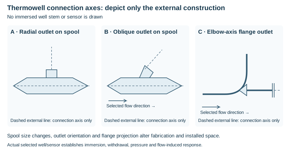
Figure 8.1. External thermowell outlet and spool alternatives.
A radial threaded outlet and an oblique threaded outlet establish different external connection axes. In the selected small-line arrangements, size-changing fittings surround an enlarged straight spool before returning to the line size. A larger-line variant attaches directly to the line. An elbow-axis arrangement instead uses its specified outlet on the elbow, a projecting pipe length and a flange boundary. Those choices alter fabrication, end preparation, mass and installed space before the thermowell is fitted.
The selected oblique and elbow details carry flow arrows. Retain them with those details rather than turn them into a preferred direction for every temperature connection. A threaded outlet, threaded lateral outlet and socket-weld/flanged elbow outlet also have different joint systems. Match the actual header size, line class, material and end preparation, including the source detail's particular spool/projection dimensions. The structured external-axis comparison records the selected construction without prescribing those catalog dimensions for another installation.
Only the external construction is shown. The dashed projection identifies an external connection axis, not an immersed stem, sensor tip or withdrawal envelope. Use the selected well and instrument to establish actual insertion, fit, removal and the mechanical conditions already described above. An outlet-axis drawing cannot establish sensing accuracy, pressure adequacy or wake/fatigue response. Carry the actual well geometry into Mechanical analysis and its physical space into Access and handling, while Fabrication verifies the spool and end interfaces.
A pressure tap senses one location and one state
Pressure indication can be local or transmitted to a receiving function. The tap, root connection, valve, tubing and instrument define both a pressure boundary and a sensing path. Preserve the material/rating break and the physical scope of each participant. A small instrument connection is still exposed to its applicable process condition. Its size does not justify an unsuitable first nipple or valve.
Locate the sensing point for its purpose. A controller regulating a downstream pressure needs information representative of that controlled region. A location immediately affected by a junction, throttling action or unstable flow can have a different signal from the one intended. The required separation and geometry depend on the selected service and instrument basis.
One location basis allocates at least six pipe diameters after a control valve or intersection. A different pressure-mixing/controller example specifies a 30-diameter minimum downstream of its junction. These are separately scoped criteria, not interchangeable measurements or a reason to adopt the larger value automatically. Retain the actual disturbance, tap purpose and diameter convention of the selected basis, and evaluate the resulting location.
Elevation and sensing-path contents can change the pressure reaching the device. In a known continuous liquid-filled path at rest, pressure increases downward with liquid density and vertical depth. A gas pocket, changed liquid, two-phase path or selected condensate leg needs its actual head/reference basis. Pressure-reference and elevation accounting provides the bounded static-head method.
Tie any zero or elevation correction to the selected hookup, fill fluid and instrument procedure. It is an installation correction, not automatically a process-pressure change or a generic subtraction from every gauge.
Keep measurement separate from pressure protection. A control valve can reduce normal downstream pressure while a different open, blocked or failed configuration exposes a region to a higher pressure. Where that credible state applies, a class break cannot be justified solely by the normal controlled reading. Pressure design establishes the actual exposed boundary and protective basis. The pressure measurement and control layout must represent the same conditions.
Flow measurement depends on the physical stream and approach
A flow device needs more than a line number and a convenient straight segment. Define the fluid, phases, pressure/temperature, expected range and measurement purpose. Process indication, control, custody accounting and leak-detection applications can have different acceptance targets. The adopted range and uncertainty basis should describe the conditions in which the device will operate, not merely its nominal size.
Differential-pressure arrangements such as an orifice assembly use a specified primary element and sensing connections. A transmitter receives the selected pressure difference and supplies the indicated, recorded or controlled flow function under its calibration basis. A venturi or an averaging pressure device uses another selected geometry. The configuration affects the approach, required lengths, taps, pressure loss and maintenance. Do not replace one form with another solely because it fits without reevaluating the measurement and process consequences.
Upstream bends, valves, branches and other disturbances affect the flow presented to the primary element. The selected straight-run basis must match that configuration and the meter's dimensional ratios. A length expressed as pipe diameters is not meaningful until its diameter and conditions are defined. A code or guide referenced historically does not establish a current requirement without its applicable edition and configuration.
For an orifice, retain diameter ratio with orifice bore and corresponding pipe inside diameter . A selected straight-run factor in pipe diameters multiplies that actual diameter. The applicable disturbance, ratio, meter basis and edition determine the factor; nominal size alone does not establish the run.
When a selected meter run does not fit, compare meaningful alternatives. Another validated element, a different route or a selected flow-conditioning arrangement may recover space, but can change pressure loss, maintenance and the measurement basis. Ask which engineering result each alternative must preserve rather than shorten a run without examining the source of its requirement.
Tap orientation and small-piping arrangement also matter. Liquid, vapor, steam and solids-containing service can require different selected hookups. A staggered tap arrangement can solve valve or flange interference while being incompatible with a prefabricated manifold. Keep the actual device, sensing connections and process phase together. Connection details develops the physical forms. Their geometric fit does not itself validate the measurement.
Phase and operating window limit what a reading means
A liquid-service meter or control arrangement should not be credited for the same function after upstream flashing changes its inlet. Phase-sensitive equipment paths shows how elevation and loss can cause that change. Evaluate pressure, temperature, density and the actual device basis, preserving the state in which the measurement is to be used. A layout drawing cannot establish single-phase operation by itself.
That limitation is different from saying that all two-phase or multiphase flow is impossible to measure. The admitted service material includes wet-gas and full-wellstream measurement arrangements. A wet-gas arrangement can use a gas-meter basis with selected correction for liquid effects. A full-wellstream system may determine quantities for more than one phase. Some selected systems do not distinguish different liquid phases. Their output, uncertainty and operating window need their own definition rather than inherit a simple liquid-meter calibration.
Flow and phase proportions can change over facility life. Gas-volume fraction, water fraction, composition, rate, pressure and temperature can move the stream outside a device's stated range. A measurement satisfactory at most conditions can still be unsuitable for a consequential interval. Select or plan alternatives around the required operating window and purpose, not a single early duty point.
Different calibrated ranges, parallel meters, exchangeable elements or selected non-intrusive arrangements can support that changing duty. A long-term change may permit a planned shutdown for an element replacement, while another service cannot tolerate frequent containment breaks. Selected computational compensation can use additional condition/composition information where the admitted metering basis supports it. Compensation is not proof that an unmeasured input or an out-of-range device becomes valid. The selected compensation method still needs its actual inputs, validity range and verification.
Do not universalize a project-specific uncertainty percentage or a lifetime-coverage target. Preserve the required output and operational window for the actual contractual, reservoir, process or protective purpose. The technology and the installation must be evaluated against that purpose, including how a changed element, calibration or bypass affects the rest of the system.
Level instruments sense a physical relationship
A local level gauge makes the selected liquid level visible through its communicating arrangement and readable range. Reflective glass, for example, has a particular viewing side. Segments or multiple gauges can cover a larger range, but their visible overlap and connection positions must reflect the actual assembly. A nominal gauge length is not necessarily its readable span.
An external cage or chamber communicates with the vessel through its selected connections. A float or displacer then responds to the liquid condition in that chamber. The instrument can represent vessel level only while the communicating arrangement is in its required state. A blocked connection, trapped phase or an isolated cage can leave the instrument sensing a different inventory. Correct calibration of the device does not correct that physical difference.
An internal float or displacer places the sensing assembly within the vessel instead. Its withdrawal connection, range and access differ from an external cage. Some selected arrangements cannot be isolated for removal in the same way. Compare the actual maintenance configuration and process service, not only the smaller footprint of the installed device.
A suspended displacer senses a density-dependent change in apparent load as immersion changes. It differs from a floating element. Its spring or torque-tube response, range and calibration must suit the actual liquid density/specific gravity and selected mechanism. A service-density change can alter the indicated level without the same change in inventory. The mechanism and pressure boundary remain particular to the selected device.
Coordinate the bridle, chamber and readable gauge span
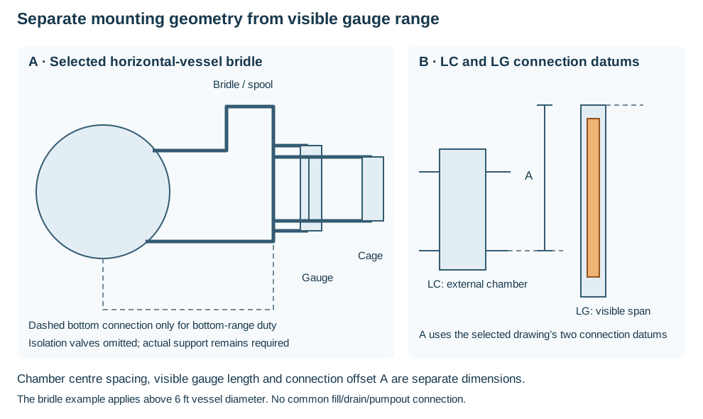
Figure 8.2. Selected bridle and gauge mounting geometry.
A selected horizontal-vessel arrangement above 6 ft diameter uses a communicating pipe spool or bridle to avoid excessively long separate connections. The bridle carries the physical gauge and external chamber connections. Its lower extension to a vessel-bottom connection is a distinct option used only when the required range extends to the bottom. Do not make it the default merely because a drawing shows it.
The diagram omits isolation valves for clarity. The actual gauge arrangement retains dedicated block valves and the vents/drains needed for its prescribed cleaning and intervention. The installed support must suit the mass, projection and service movement.
Keep the external displacer chamber, denoted LC in the selected construction, separate from the visible level gauge LG. Chamber connection center spacing describes one geometry. Visible gauge length describes what can be read. The elevation difference A compares the specified LC and LG connection datums. These are not a differential-pressure calibration diagram or interchangeable dimensions. A correct overall mounting height does not establish complete readable coverage between segmented gauge windows.
One class-specific mounting table applies to ASME Classes 150, 300 and 600. It relates a 356 mm chamber center spacing to one two-element gauge with 670 mm visible length and A from 90 to 394 mm. A separate 813 mm chamber spacing uses one three-element gauge with 1,036 mm visible length and A from 102 to 315 mm. Its 2,134 mm chamber-spacing row instead uses two two-element gauges plus one three-element gauge. It has 2,326 mm visible length, a standpipe and A from 102 to 284 mm.
These selected rows illustrate the different references. Their A convention assumes that the individual gauge with the longest visible length is placed at the top when several gauges are required. They do not dimension another product, pressure class or segment sequence. The structured mounting relationships preserve those exact selected rows and conditions.
Keep the communicating connections dedicated to the level arrangement. The selected vessel mounting basis excludes sharing them with fill, drain or pumpout services. Establish the actual cage and gauge, material/rating, readable overlap, valve access, cleaning path and support before releasing the installation. Small-bore connection duties and Work envelopes provide the connected physical checks. This mounting account adds no control architecture.
Calibration and installation have different errors
Checking a receiver's range or a transmitter's response can establish only part of the sensing chain. It does not prove open, representative process connections or free displacer movement. Nor does it prove that the indicated quantity uses the right fluid condition. A nearby check-point thermowell or local gauge can support a comparison. Before one reading is simply declared wrong, a difference should be investigated through the actual sensor, connection, reference and state.
Changed service can reopen the calibration basis. Density, phase, temperature or flow range can change the relation between a physical quantity and the signal used to infer it. Reevaluate the affected sensing and conversion rather than assume that an unchanged instrument tag means an unchanged valid measurement. Operating integrity and engineering records preserve the relevant condition and revision.
Differential level includes the contents of both pressure paths
A differential-pressure level arrangement compares the pressure supplied to its high and low sides. In a closed vessel, the common gas pressure can cancel while liquid head remains. That cancellation requires both paths to communicate with the intended pressure regions. Their elevations and contents still contribute to the result. The device measures the pressure difference reaching it. It does not directly observe the liquid surface.
Trace each pressure path from its tap elevation to the selected cell port, including every rise/fall and its intended gas, process-liquid or reference-liquid contents.
A known, maintained liquid reference leg can be included in calibration. An intended gas leg that gradually collects condensate creates a changing head. Both can contain liquid, but they have different design premises and verification needs. A zero adjustment cannot make an intermittently filling path into a stable reference.
This matters especially in a long, sloping, multiple-pipe slug catcher. The gas reference connection may traverse much of the equipment length before reaching the cell near the liquid header. Cooling along that path can condense liquid. Sludge near the header bottom can obstruct the liquid tapping. Water, glycol and condensate can also produce different density distributions in neighboring bottles. The system therefore needs more than a transmitter range: it needs a communicating arrangement whose actual contents remain consistent with the inferred level.
One selected arrangement slopes the gas impulse pipe parallel to the bottle, provides generous drainage space, and places a drain knockout pot before the cell. Its illustrative gas connection is approximately 50 mm, shown as a 2 in pipe detail. These are separately stated size conventions rather than an exact bore conversion or a minimum for every instrument. The liquid-side tap is 45° around the header from its lowest point, reducing exposure to bottom sludge. This placement avoids the dirtiest part of the header. It does not prove that a connection cannot block.
The drain pot collects liquid from the reference path, while the header drain serves a different inventory.
Each needs its selected containment, pressure rating, access and safe drainage arrangement.
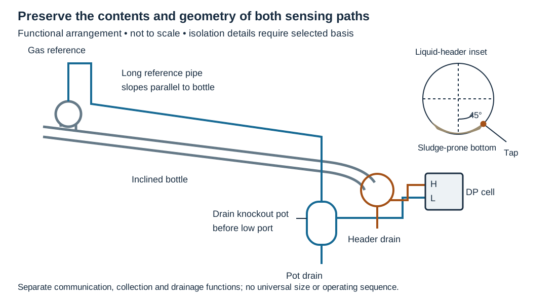
Figure 8.3. A functional side view separates the long gas reference path, its drain pot and the liquid-side sensing connection. The header inset identifies the selected tap relative to bottom sludge. It is not to scale and gives no drain operating sequence or isolation specification. Structured paths and geometry.
A compact vessel bridle offers a different tradeoff. Several instruments can share vessel connections, with suitable isolation and independent support for a heavy assembly. This may reduce penetrations and simplify removal, but it introduces a shared communicating path: a closed or obstructed root can affect several readings at once.
The selected slug-catcher arrangement excludes instrument bridles for its integrity basis. That exclusion belongs to this equipment route. It does not establish that every vessel bridle is unsuitable. Compare the actual service, sludge, density distribution, support loads, maintenance boundary and required independence before selecting either arrangement.
For this bounded static head model, write the pressure-head terms after the common gas pressure and all known fixed installation offsets have been removed:
In these equations, is the vertical thickness of liquid layer above the liquid tap and is its density. The variable is the additional continuous vertical liquid head on the low-side reference path, and is that liquid's density. The calibration density is . This simplified model assumes negligible gas-column head. Cancellation of the common gas pressure does not cancel hydrostatic gas head. Where that contribution is material, include the actual gas and liquid pressure-head integrals.
Heights are in m, densities in kg/m³, in m/s² and pressure difference in Pa. The minus sign applies because added low-side head reduces high-minus-low pressure.
The reference term describes a continuous column supplying that head to the low port. A shallow pool with gas communicating around it is not automatically a column of the same vertical height. Where the path contains several liquid or gas regions, use their actual pressure-head integrals and elevations.
Layering and added low-side liquid head can produce opposite indication errors. Partial cancellation at one condition does not validate the hookup or conversion. Structured head/conversion method and units.
Select an observable level before choosing compensation
A single differential reading cannot generally resolve both total liquid depth and an unknown interface between liquids of different density. Several combinations of layer heights can produce the same head. Select the required output: total inventory, a particular liquid interface, liquid approaching a gas outlet or another defined process condition.
A long inclined bottle also has different elevations along its length. Thus selected taps and observed regions must use the same geometric datum as the intended output.
One compound-liquid approach uses multiple differential cells connected at predetermined heights. Its design premise includes knowing the maximum glycol level when locating those taps. The additional readings can constrain the inferred distribution, but retain the conditions that remain uncertain. Adding cells does not independently determine every unknown composition, density or blocked connection. Define how the selected combinations distinguish the required conditions and what observations would invalidate the conversion.
A different approach places gamma densitometers along the bottle. A horizontally oriented beam supplies a density-sensitive response through its selected chord, while several longitudinal positions observe different regions. This can provide information about denser liquid that a single total-head reading cannot separate. It still requires a selected calibration, geometric coverage, composition basis and operating range. A signal amplitude should not be credited as instant, unambiguous glycol identification for every mixture merely because one example proposes that interpretation.
Neither arrangement alone establishes a complete protective function. Its sensing, logic and final action retain the distinctions developed earlier.
Table 8.1. Level arrangements, available information and premises.
| Arrangement |
Physical information available |
Premise to retain |
Consequence for the design |
| One differential cell |
Integrated pressure head between the supplied references |
Known path contents and usable density conversion |
Unknown layering can resemble a change in total level |
| Multiple cells at selected heights |
Several head relationships over different regions |
Predetermined taps and a defined maximum interface range |
More constraints, with remaining uncertainty and shared-path failures evaluated |
| Gamma measurements along a bottle |
Density-sensitive response over selected chords and locations |
Calibrated mixture response and actual coverage |
Another observable, with its own uncertainty and installation requirements |
| Communicating local gauge or chamber |
Local inventory in its connected region |
Open, representative connections and readable range |
Can corroborate a condition, but can also remain trapped or unrepresentative |
Implement the selected method with inspectable paths. Provide access to the actual tapping, pot, valves and device. Support the assembly without loading a small root or restraining equipment movement unintentionally. Preserve slope and low points after erection rather than rely on a line drawn at a nominal fall. Insulation or tracing may control phase changes where the service basis supports it, while changing heat input can alter fluid density or temperature. The thermal treatment and the measurement basis need to agree through normal operation, standby, startup and shutdown.
Verification should separate several questions. Does the cell respond to a known differential input? Are the process and reference paths in their selected communicating state? Does the conversion represent the current liquid distribution and density? Can the receiver and selected control action use that output? A satisfactory answer to the first cannot substitute for the others.
Following maintenance or cleaning, restore the specified path contents, connections, mode and reference condition through readiness and intervention. Investigate path blockage, condensate accumulation, composition and actual inventory before adjusting zero or treating a drifting reading as proof of a process change.
A control valve is an adjustable flow path with a selected action
A control valve throttles through its selected body and internal arrangement. An actuator moves the controlling member. Globe forms are common in the source-described arrangements, while ball, butterfly and other forms can serve particular duties. The selected flow direction, body, actuator and travel must be understood together. Hardware and joints develops their component behavior. This chapter connects that hardware to the sensing and control function.
An actuator may respond to pneumatic, electrical, hydraulic or other selected signals. A handwheel or handjack can provide a specified manual action. Those are different operating modes, not evidence that every signal loss results in the same valve position. Establish the actual action and failure or standby state for the selected service. Keep protective requirements with their governing basis.
Thermal and mechanical details affect the installed envelope. A selected cooling extension or fins can separate hot body conditions from the actuator, increasing height and changing clearance. A horizontally oriented assembly can introduce support and lubrication issues different from the usual vertical arrangement. Use the actual supplier configuration. Do not turn a historical temperature threshold or example actuator clearance into a universal rule.
Pressure and flow direction matter at the body. An angle arrangement or special-duty valve can have a selected side/bottom connection and flow path. The certified outline and service information establish that path. A control signal that moves the actuator does not prove that a wrongly connected valve provides the intended process function.
Control location should serve both information and action. An operator manually regulating vessel level needs the relevant indication visible from the operating position. A remote function needs the selected transmission and receiving interfaces. Shorter connection lengths can be useful, but are not the only criterion: process representativeness, access, signal arrangement and the actual equipment envelope must remain coherent.
Stations provide operating modes, not automatic equivalence
A control-valve station can combine the control valve with upstream/downstream blocks, a bypass and selected drains. Its purpose can include continued operation while the control valve is being serviced. The station is therefore more than an arrangement of equal-pressure-rated valves. It creates different fluid paths and intervention states.
In normal automatic operation, the selected control path carries flow under its sensing and actuator arrangement. In a manual-bypass mode, flow can use another valve and path while the control valve is out of service. The operator needs the appropriate indication and means of adjustment. That mode need not preserve the automatic response, accuracy or protective functions of the normal arrangement. A bypass valve is not an automatic substitute for the controller.
When the control valve is removed, its isolation, trapped contents, opening and remaining pipe support need the applicable work procedure. The presence of two blocks on a drawing is not by itself proof of positive isolation for every service. Special services, maintenance and intervention establish their required boundaries, while supports examines the partly dismantled assembly.
Valve and actuator removal should be physically possible. A flanged valve, a ring-joint connection and a screwed or socket-welded arrangement can need different break-out geometry. A removable elbow or the selected unions/spools may provide the required path. The body, actuator, handwheel, flanges and nearby vertical branches all occupy space. A station that can be bolted in place but cannot release its valve has not met its maintenance purpose.
Steam stations add condensate and temperature conditions. Their block, drain and support arrangements may differ from an ordinary liquid station. Coordinate the selected service rather than copy a universal station template. Likewise, a manual-handwheel arrangement and a station with a bypass can be alternatives rather than mandatory simultaneous hardware. Describe the actual selected configuration and the conditions under which each mode is used.
Locate the complete instrument and the work it needs
Instrument location must satisfy sensing conditions and practical access. The P&ID identifies a function and connection. The instrument information supplies the dimensions, range, mounting and selected hookup. Coordinate these with vessel internals, piping, structures and the operator's task. A connection point alone is not the complete installed object.
Readability requires the intended line of sight and viewing side. Orientation, elevation and a swivel or fixed head can change whether a gauge is usable. Vessel level gauges can need their readable range aligned with the selected operating levels. A local flow or temperature indication used while adjusting a valve should be visible from that work position. It should not require viewing around another line or from a different platform.
Removal needs a path for the inserted or housed element. Thermowells, probes, level assemblies, valve actuators and panels can each require a different envelope. Do not use the space around a bare coupling as evidence that the assembly can be installed or serviced. Spatial and work envelopes supplies the common method, while this chapter supplies the particular instrument and signal requirements.
Mechanical environment also affects a reading and its boundary. A transmitter mounted on a vibrating structure can load its small connections and lose function. Thermowells and small-bore instrument branches have their own mechanical susceptibility. Mounting and support should preserve the sensing path and actual connection requirements without creating another thermal or vibration problem. Mechanical analysis and supports develop the evaluation.
Access categories differ with service and task. A portable means may be suitable for a particular meter inspection, while frequent operating action or a heavy actuator needs a different arrangement. Choose from the adopted task/access basis and actual equipment. A historical list saying an item needs no permanent access does not establish that every future maintenance job is achievable.
Restore the function after testing or maintenance
Instrumentation can be installed, isolated, bypassed or partly removed while the main line is tested or maintained. A test boundary and pressure state can differ from normal service, and the sensing devices may need their specified treatment. Verification and readiness coordinates these changes. A successful test of the main line does not prove the final measurement or control state.
Restoration should identify which connections and communicating paths must be open or reassembled, which temporary conditions are removed, and which operating mode is intended. A valve left isolated can make a level cage or pressure indication represent a trapped condition. A bypass left in another position can change the controller's authority over flow. Verify the actual function rather than count installed tags.
Check the process connection, sensing mechanism, signal/receiving function and final element against the selected basis. Preserve calibration/range and fluid/reference information, confirmed mounting and removal clearances, action/direction and remaining limitations. These records allow later observations or service changes to reopen the right part of the chain through engineering continuity. They are evidence of the actual state, not a second source of engineering truth detached from it.