Chapter 3 — Components and pressure-retaining joints
Choose what the component must do
Select components for their required flow function, coincident service conditions, loading, joints and maintenance access. For valves, specify body containment, seat shutoff and external sealing separately: pressure class establishes neither tight shutoff nor low external emissions.
The materials and class selected in Materials and piping classes provide the starting component requirements. Read the size-dependent selections and service notes as well as the general class designation. Body material, trim, seat, packing, bolting and end connection need compatible conditions. A material suitable for the body may be unsuitable for a moving stem, a soft seal or a seating surface exposed to erosion. The installation must also leave room to operate the component, inspect its leak paths and remove the parts that its maintenance requires.
Direction, area and connection geometry have consequences
Turn radius affects space, flow resistance and local mechanical response.
A short-radius elbow can fit where a longer turn cannot, but that compactness is not a free improvement. For fitting selection, evaluate the actual rating, pressure loss and stress consequences. In the historical ASME B16.28 short-radius fitting comparison, the rating is 80% of that calculated for seamless pipe of the same size, material and nominal wall. That factor belongs to that fitting and edition basis.
The matching wall designation alone does not establish capability.
Bending avoids some fitting welds and can be useful for large or heavy-wall systems. It also changes wall distribution and section shape. Forming must preserve the required minimum wall and flow area and meet the material’s fabrication and heat-treatment requirements. A miter can be practical in a suitable large, low-pressure arrangement, but its welds and direction discontinuities intensify stress and flow disturbance. Cyclic thermal or vibration loading can make those details consequential. Welding and Fabrication develop how those choices are made into acceptable parts.
Choose concentric or eccentric reducer orientation to preserve the required top or bottom profile and avoid gas or liquid pockets that impair suction, drainage or readiness. A tee or outlet fitting creates a branch whose opening, reinforcement and attachment loads need the connected explanation in Branches and small-bore connections.
Dimensional designation must not conceal incompatible bores. A fitting heavier than its connecting pipe can require a prepared transition for weld fit-up, with the required wall preserved. Factory-made wrought fittings and forged socket-welded or threaded fittings use different dimensional and rating routes. For fittings rated by comparison with equivalent pipe, material, associated wall, manufacturing tolerance and applicable allowances enter that comparison. A fitting class number is not a pressure in psi.
Strainers add another function: intercepting solids before they reach equipment or a sensitive component. For the service, select the screen or basket opening, accessible cleaning arrangement and pressure capability. The device can accumulate material, increase pressure drop and become an obstruction. Its clean condition cannot stand for its loaded condition when evaluating equipment supply or a relief path.
A temporary startup screen remains part of that protection until its specified duty is complete and the applicable release conditions permit removal or replacement. Temporary removal for cleaning is a separate intervention. Before resuming the duty that requires protection, restore the screen or establish the specified replacement protection.
Isolation, throttling and nonreturn require different behavior
A gate valve places a wedge or disc across the flow. When fully open, the passage generally offers relatively low resistance. Its geometry makes it a familiar block valve, but prolonged throttling is a different duty. Seating loads, thermal distortion and piping moments can affect operation. Wedge and seat arrangements, bonnet construction and trim should be evaluated for the temperature, service and operating requirement rather than selected by a simple size rule.
A globe valve moves a disc or plug toward a seat across a changed flow path. Plug shape provides different opening characteristics: a flat disc can open quickly, whereas a needle shape changes area more gradually. The changed direction of flow usually produces greater pressure loss than a straight-through gate arrangement. Angle and Y-pattern bodies modify that route. This geometry is useful for throttling and can also be selected for demanding block service when its losses and operating behavior are acceptable.
Ball valves rotate a bored ball through the flow path. Full and reduced ports change the open flow area, mass and cost. A full port can be required where pigging or a particular intervention must pass through the valve. In a floating-ball design, differential pressure helps force the ball against its seat.
In a trunnion-mounted design, the ball is restrained while the seats are loaded toward it. Springs can provide seating at low differential pressure. Seat and body-seal construction therefore matter beside the body rating. A trapped body cavity can need a pressure-relief arrangement when liquid warms or when the selected isolation arrangement closes both sides.
Plug valves offer another rotary closure, with lubricated and nonlubricated seat arrangements that have different service and maintenance requirements. Butterfly valves rotate a disc in the flow path and can offer a compact, relatively light component. Disc and shaft offsets change how the disc contacts or lifts from its seat. Resilient seats, metal seats and laminated seating constructions do not have identical temperature, wear or fire behavior. A historical preference for a particular offset design should retain its service and evidence basis. Compactness or a metal seat alone does not prove suitability for every duty.
Check valves need enough forward-flow force to open appropriately and an effective response when flow falls or reverses. A swing disc pivots from the stream. Lift and ball checks depend in part on gravity and correct orientation. Piston checks may use pressure and spring assistance.
Tilting-disc and split-disc arrangements change inertia and closing response. Frequent reversals, pulsating flow and closing speed influence wear and surge. Selecting “a check valve” without those conditions can produce a device that chatters or closes poorly. A stop-check combines a nonreturn function with a means of holding the disc closed.
The isolation duty of the actual design still needs to be established.
A flexible wedge permits limited elastic adjustment of seating faces under temperature change or small misalignment, reducing binding in its intended duty. It does not guarantee sealing or tolerance of arbitrary piping loads. Body/wedge guides, the stem-to-disc connection and seating contact must maintain alignment without lateral stem strain. Body distortion, worn guides or unsuitable seats can impair operation even when the actuator moves.
Globe/angle disc shape and seat construction determine opening behavior. A swiveling stem connection can permit seating alignment. Body rating does not establish trim, seat, bonnet or stem-seal suitability.
Check-valve selection needs actual gravity/spring arrangement, flow forces and internal clearance through full motion. Do not assume a spring in an unspecified swing construction or evaluate suitability from open-port area alone.
The comparison needs the actual duty. A manual bypass used intermittently has a different frequency and duration of throttling from a valve regulating continuously. That distinction can justify considering a simpler arrangement, but only if its flow behavior, pressure loss, wear and operating task meet the selected service requirement. Infrequent use does not prove that a smaller gate is an adequate substitute for a globe. Conversely, the word bypass does not require one body pattern independent of its job. Control stations carries the selected manual mode and information/action relationship into the system.
Include the open and intervention configurations
Operating dimensions must represent what moves. One selected rising-stem gate has an axially retained rotating yoke-sleeve arrangement. As the valve opens, the stem projects while the wheel can remain at its operating height. In the illustrated globe and angle arrangements with a handwheel attached to the stem, the wheel rises with the stem. An envelope based only on the closed position can miss either projection.
| Selected construction |
Geometry to represent |
Consequence for the task |
| Gate with rising stem and retained yoke-sleeve operator |
Open stem projection and actual wheel diameter/position |
Clear the complete stem travel while preserving access to the operating wheel |
| Globe or angle with handwheel moving with stem |
Open handwheel height and swept wheel envelope |
The operator and adjacent piping must allow the translated wheel as well as its rotation |
| Geared or powered operator |
Actual gear/actuator shape, drive location and removal requirements |
Equal valve face-to-face dimensions do not establish equal operating or maintenance envelopes |
| Check valve with removable cover and internal closure |
Cover opening, closure withdrawal and handling path |
No external operating stem does not mean no maintenance space is required |
Table 3.1. Operating and intervention envelopes depend on the selected construction. Structured envelope comparison.
Some class methods assign gear operators by size and pressure class while expressly allowing differential pressure to change the selection. Those thresholds describe a particular selection basis. For the operating envelope, evaluate the actual operating load, selected drive and supplier dimensions. Do not inherit a plain-handwheel envelope from a table that excludes gears. Work envelopes supplies the common access and handling method; the component construction supplies the motion that method must accommodate.
Orientation also changes what can accumulate. A bonnet cavity below a flowing line can collect debris or condensate. A position that reduces such collection can change access or support needs. Check-valve orientation changes how gravity acts on its disc, while pulsating flow can repeatedly excite the closure. These are physical configuration questions. They cannot be resolved by rotating a catalog symbol for drawing convenience.
Table 3.2. Valve duties and hardware consequences.
| Required behavior |
Hardware questions |
Consequence to evaluate |
| Block flow |
Seat construction, differential pressure, direction, leakage basis and operability |
Passing seat, trapped cavity and ability to isolate the intended boundary |
| Throttle continuously |
Plug/port characteristic, pressure drop, trim, actuator and packing friction |
Stable control, cavitation/erosion, noise and required operating force |
| Prevent reversal |
Opening differential, disc inertia, spring/gravity effects and orientation |
Chatter, delayed closure, slam and pressure surge |
| Permit pigging or intervention |
Actual bore, port and passage geometry |
Whether the required tool can pass; reduced port cannot be assumed adequate |
| Limit external leakage |
Stem/shaft, packing, bonnet and body joints |
Emissions, condition monitoring and maintenance access |
The operator must move and hold the selected valve under its credible differential pressure, temperature and friction. Manual levers, gear operators and powered actuators change operating effort, closure speed and access. Rapid closure can create surge. A slow or undersized actuator can fail to perform the required action.
A valve used for emergency action needs a defined response to loss of its power or actuation supply, coordinated with the protection system. Measurement and control explains the control interaction and Pressure protection explains the system duty. The hardware choice must support those functions.
Bonnet and end connections affect repair. A bolted bonnet offers access with an additional pressure-retaining joint and mass. A welded bonnet can reduce leak paths and mass but restrict repair. Outside-screw-and-yoke construction keeps stem threads outside the fluid and makes stem travel visible.
Stem retention must be a mechanical feature of the design. Packing friction is not a dependable substitute for it. At a small-bore root valve, the mass saved by one construction can affect vibration while the loss of repair access affects the maintenance plan.
Select the joint as part of the installation
Butt-welded joints can provide a continuous metallic boundary with few dismantling interfaces. Their integrity depends on material, preparation, alignment, welding, heat treatment and examination. Removal generally requires cutting or opening a different joint. Socket-welded joints simplify some small-bore assembly but introduce a local geometry and crevice.
Cyclic loading, cleanliness and crevice-corrosion concerns can change their suitability. Threaded joints permit assembly without welding but remove wall, introduce thread-root stress concentrations and require compatible sealing and service conditions. An adopted class’s exclusions of either joint remain binding for that class.
A flange provides a separable connection for equipment, valves, blinds and spools. That access brings a gasket, bolting and seating surfaces that must remain a functioning assembly. Welding-neck, slip-on, socket-welded, threaded and lap-joint arrangements transfer load into the pipe differently. A rotating lap-joint flange assists bolt-hole alignment, but its freedom and stub-end arrangement are not equivalent to a welded-neck flange. Attachment and service limits must follow the chosen form.
Unions and tubing connectors offer compact removable connections. Compression and bite-type fittings require the specified tube material, dimensions, end preparation and assembly. Mixing similar-looking parts or using damaged tubing can defeat the intended seal. A small fitting with a pressure marking still needs support and protection from mechanical loading at the connection.
Grooved and plain-end couplings can simplify assembly and accommodate limited misalignment or motion in qualified services. Some do not provide axial restraint. A sealed slip connection can separate under pressure thrust unless the installation provides a suitable restraint. Elastomer compatibility, fire exposure, hydraulic shock and temperature limit the choice. Flexibility at a joint should therefore be described by permitted motion and retained load path, rather than treated as unrestricted movement. Mechanical analysis and Supports and restraints develop the connected evaluation.
Separate the flange attachment from the separable seal
Evaluate the pipe attachment and mating seal separately; either can fail while the other remains sound.
A welding-neck flange uses a prepared butt joint at its neck. Its bore and end preparation must match the connecting pipe under the selected transition rules. The tapered neck and completed weld form part of the load path into the pipe. A compatible nominal size does not prove that the inside diameters or required walls match.
In the illustrated slip-on form, the flange fits over the pipe and is attached by specified front and rear welds. The pipe-end setback provides the geometry for one construction. Another specified form uses a prepared front groove and refacing. They are not interchangeable fabrication sketches. The selected weld configuration and dimensions must establish the attachment and preserve the sealing face without assuming that a convenient slip fit is itself a pressure-retaining connection.
A threaded flange uses its engaged threads as the mechanical connection. Where a rear seal weld is specified, that weld closes a potential leakage path through the threads. Its sealing duty does not automatically make it a qualified strength weld or justify unspecified structural credit. Preserve the selected joint design, thread engagement, material and weld procedure rather than treat adding a weld as a universal upgrade.
A lap-joint arrangement separates the rotating flange from the stub or lapped end. The flange bears on that end to transmit the bolting action. The end presents the sealing face, and its attachment continues the boundary into the pipe. Rotation can ease bolt-hole alignment. It does not remove the need to match the flange/stub geometry, material, facing, gasket and load basis. Nor does that rotation establish unrestricted movement after the joint has been tightened.

Figure 3.1. The sections distinguish pipe attachment from the mating sealing face. They are schematic constructions, not weld sizes, tolerances, pressure ratings or permission to interchange forms. Structured recreation data.
These distinctions affect removal. A separable gasketed interface can permit opening a selected spool while a butt-welded attachment remains intact. A changed flange form or longer neck can alter the break-out geometry. Keep face, end and center datums with the actual component dimensions. A face-to-face dimension that includes the specified facings cannot be replaced by a dimension to an unfaced body plane. Spool description and fit-up carries the selected datums into fabrication, while Connected loads and supports preserve the mechanical interfaces.
Attachment choice carries load and service conditions
The rotating backing flange of a lap joint helps align bolt holes, but the stub end still transmits the pipe's pressure, weight and thermal loads into the joint. Its thickness, bearing shoulder, face flatness and parallelism therefore matter independently of that convenience. A backing flange of another material also creates a galvanic compatibility question. Rotation during fit-up does not demonstrate that the loaded assembly is suitable.
An adopted metallic selection basis illustrates how these checks can constrain alternatives. It excludes slip-on flanges above 500°F, at Class 600 and higher, and in cyclic or erosive service. It excludes lethal service and corrosive service with a specified corrosion allowance above 1/8 in. It restricts aggressive environmental service with specified material/service exceptions.
It assigns weld-neck or long-weld-neck construction to vessel and exchanger connections and excludes welding a slip-on directly to a welding fitting. Those are conditions of that selection basis, not permission inferred from a slip-on flange's nominal rating. Its lap-joint route has its own 750°F and Class 600 restrictions, a combined longitudinal stress check at the pipe design temperature, specified wrought stub ends and forged backing flanges, and no ring-joint gasket. Its stated stub-end flatness tolerance is 0.0035 in over the circumference, or 0.0889 mm, with front and back faces parallel.
This geometry criterion is separate from the permitted stress. Substituting an ordinary slip-on for the specified backing flange would lose the substantiated construction.
The same basis calls for a confirmed bending-load calculation when diameter exceeds NPS 12 and design temperature exceeds 650°F, or when diameter exceeds NPS 24 at any temperature. These triggers identify where that procedure requires further evaluation. They do not give a general exemption below the trigger or supply an allowable nozzle load. Establish the selected flange calculation, actual external loads and equipment interface through Connected loads. A catalog rating cannot resolve rotation or uneven seating caused by the installed piping.
A local joint permission can require several conditions together
Threading removes wall and changes the connection geometry, so a pressure class on an adjacent flange cannot establish the permitted threaded duty. A bounded pipeline-class example applies to the two nominal sizes 3 NPS and 4 NPS. It limits their threaded piping to 3,500 kPag, requires non-cyclic service and requires fluid of low vapor pressure. All of those conditions belong to that local permission. It is not a three-quarter-inch rule, a permission for every size in the class or a pressure-only allowance.
The size, pressure, non-cyclic duty and low-vapor-pressure conditions must all be established. Unknown duty or vapor pressure leaves eligibility unestablished; no numerical vapor-pressure cutoff is supplied. Other sizes follow their own applicable basis.
Meeting the note establishes only its local conditions. The actual material, wall after threading, joint construction, service limits, governing code and fabrication/verification requirements remain part of selection. Another class can restrict the available threaded component sizes differently or specify another rating for threaded and socket-welded fittings. No such condition is supplied by carrying over the preceding class number. Class application establishes those relationships.
A separate pair of selected small-bore families excludes threading for its 1½ NPS fittings, nipples and flanges because of wall-thickness constraints. That attached note identifies a geometry limit distinct from the same families' primary-process threaded-joint exclusion. A pressure comparison cannot restore wall removed by the thread, and meeting a service permission cannot erase an attached component constraint. Follow the size and item association through to the selected socket-welded or other permitted construction; do not extend either note to an unrelated class.
Separate isolation capability from the live state
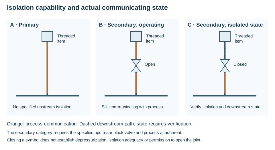
Figure 3.2. Primary and secondary threaded connection capability and state.
A primary connection in the selected sour-service route communicates directly with the process without its specified upstream isolation capability. A secondary connection has the specified upstream block valve attached to the process through its required welded, flanged or welded-fitting construction. This describes the physical arrangement. With the valve open, the secondary threaded item still communicates with the process and sees its applicable condition. The category does not mean that it is normally unpressurized.
Closing the valve changes the intended path but does not establish the downstream condition by itself. Verify the isolation boundary, retained contents and depressurization under the actual intervention procedure before relying on that boundary. An upstream valve connected through an ineligible attachment cannot be assumed to confer the required secondary category. The structured topology and conditional matrix keep capability, operating state and adopted eligibility separate.
The following matrix records one selected historical route. Its sour, severe and critical categories depend on that route's separate service and material specifications; they are not interchangeable with the H₂S concentration descriptions in Sour service. Critical-sour design is outside that specification's scope even though its table contains critical-column instrument entries. Establish the governing category and complete adopted basis before using a cell.
| Application / connection |
Sour category |
Severe category |
Critical category |
| Piping/equipment primary |
Conditional A |
Excluded |
Excluded |
| Piping/equipment secondary |
Conditional A |
Conditional A |
Excluded |
| Instrument primary |
Conditional B |
Excluded, with specific exception route |
Excluded |
| Instrument secondary |
Permitted within adopted route |
Permitted within adopted route |
Table entry permitted; critical design needs its separate basis |
Condition A permits liquid-hydrocarbon/oil systems, or gas and multiphase systems within the stated ANSI Class 600-or-lower restriction. That class restriction is not a pressure in psi. It excludes service with fatigue-damage risk from vibration, thermal cycling or pulsation. Condition B carries consideration of a tapped blind flange that can be replaced after corrosion or thread damage. The primary-instrument exception applies where no reasonable alternatives exist and requires concurrence of the designated owner's representative. It does not grant an exception for piping/equipment or extend the table beyond its scope.
Whenever this sour-service threading route is adopted, also preserve the less-than-NPS-2 diameter, Schedule 80 minimum wall, cut-thread requirement and avoidance of liquid-water collection areas. Rolled threads require written engineering concurrence, suitable subsequent heat treatment, thread-root microhardness below 248 HV₅₀₀ and supporting test data. Applicable codes, standards and specifications remain simultaneous conditions. These requirements coexist with the component-wall and class restrictions above. An isolation category cannot override them.
A flange seal depends on retained compression
Bolts pull flange faces toward one another and compress the gasket. The gasket must conform sufficiently to its seating surfaces to seal, while retaining suitable strength and recovery through pressure and temperature changes. Internal pressure creates separating effects. Flange rotation and external moments can redistribute compression around the joint. A high average bolt load does not prove that every part of the gasket remains adequately seated.

Figure 3.3. The figure separates bolt-induced closure from pressure-induced separation. It is a qualitative section, with two representative bolts. It does not specify a gasket, flange geometry, bolt load or allowable pressure.
For flange selection, choose the facing, gasket and bolting together. A flat full-face gasket, a ring gasket on a raised face, a spiral-wound gasket and a metallic ring in a machined groove depend on different contact arrangements. Gasket thickness, filler or core material, confinement and flange finish affect seating. Graphite can be useful in many hot services and unsuitable for a strongly oxidizing chemical environment.
PTFE offers useful chemical resistance and low friction but has its own deformation and temperature limits. Metallic windings, rings or jackets likewise need compatible materials. A gasket chosen solely by nominal diameter cannot establish the intended joint.
Bolt material determines strength and environmental/temperature suitability. Nuts, thread form and engagement, washers where specified, and lubrication affect the load generated during tightening. Low-temperature, hot and sour-exposure requirements can demand different bolting. High-strength bolting applied to a fragile flange does not automatically improve the assembly. The component’s permitted seating load and the actual procedure remain essential.
Torque is an indirect route to bolt load because friction consumes much of the applied effort. A change in lubricant, thread condition or nut-bearing condition may cause a previously chosen torque to produce a different load. Torque tables therefore belong to a defined bolting, gasket, flange and lubrication basis. A number copied from a superficially similar joint is not a complete procedure. Equally, forcing poorly aligned piping together can impose pipe strain and equipment loads even if the bolts reach their target torque.
Relate the torque setting to its assumed preload
A useful approximate model writes tightening torque as a nut factor multiplied by nominal bolt diameter and preload. On a consistent inch-pound basis,
In these equations, is torque in ft·lbf and is a dimensionless empirical nut factor. Nominal bolt diameter is in inches, and bolt preload is in lbf. The selected tensile stress is in lbf/in². The effective thread stress area is in in².
The factor 12 converts in·lbf to ft·lbf. The thread stress area is not the gross circular area formed from . Thread form, material strength and the selected stress basis remain separate inputs. In consistent SI units the same model is , with torque in N·m, diameter in meters and preload in N.
The inch-to-foot divisor does not carry into that expression.
The model explains a consequence of table selection. It does not determine the required preload. That selection must address gasket seating and retention, bolt strength, flange load and deformation, service and the adopted assembly procedure. Nor does an assumed prove the actual friction or scatter of a used assembly. Lubricant, threads, nut-bearing surfaces and any specified washers must match the basis. Lubrication intended for threads is not permission to lubricate a gasket or sealing face.
The tabulated torque bases also preserve assembly state. A selected procedure's tables apply at unpressurized, ambient conditions, with its stated 40–100°F ambient range. Internal floating-head bolting has a different lubricant, fine/coarse thread distinction and material/stress basis from general external bolting. A local higher stress fraction needing engineering disposition is not selected by choosing the largest table value. Before applying the stages below, preserve the joint identity and actual adopted procedure. This calculation supplies no warm or live-tightening permission.
Match the ring, groove and assembly datums
A metallic ring joint depends on the selected ring profile engaging compatible groove surfaces. In the illustrated ring family, an oval profile can be used with the specified flat-bottom or rounded-bottom groove forms. An octagonal profile requires the flat-bottom form. That is a profile-compatibility distinction within those constructions, not proof that every oval ring, octagonal ring or flange groove is interchangeable. Match the actual dimensions, material and service basis as well as the profile name.
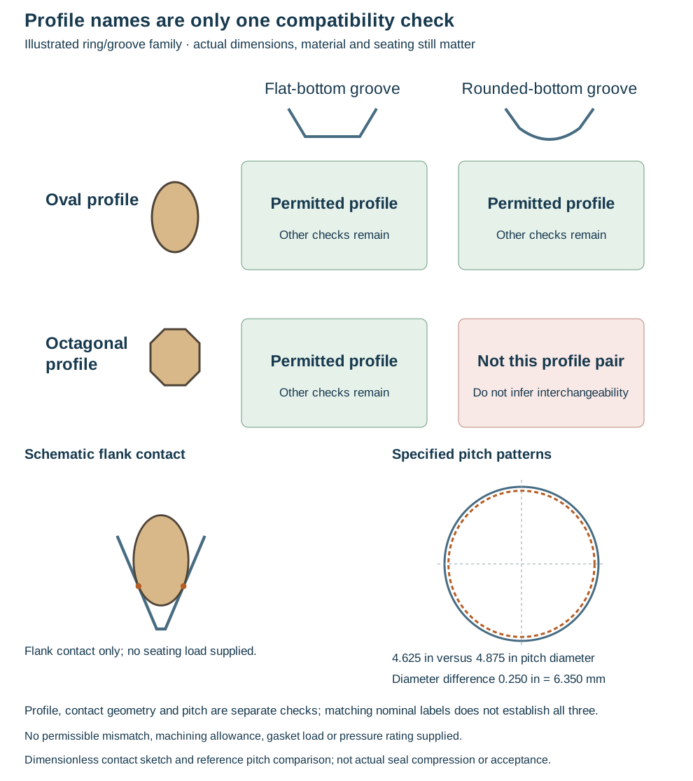
Figure 3.4. The matrix records the illustrated profile relationships. The dimensionless flank-contact sketch and common-scale pitch patterns show separate geometry checks. A permitted profile pair still needs the actual ring/groove dimensions, material, seating and service checks. It is not a pressure-tightness result. Structured profile comparison.
Match pitch diameter independently of nominal size and class. The specified reference details at in and in do not coincide. That comparison supplies no allowable mismatch or machining permission; use substantiated compatible mating parts.
An assembled ring joint can retain a gap between the opposing flange faces after the studs are tightened. A drawing's approximate gap is not a required universal zero and is not a direct measure of gasket seating load. Likewise, a stud-length or assembly dimension stated for one construction may not apply to a lap arrangement with a different end thickness. Preserve the actual face/end/center references, ring geometry and bolt engagement rather than force an unfamiliar detail into another table's letters.
Replacement requires matched ring/groove geometry, facing and material, sound surfaces and the selected tightening basis. Condition assessment and intervention carry wear and restoration requirements.
Compatibility includes material, facing and exposure
For a metallic ring, profile and pitch agreement leave the material question open. The ring must conform at the selected contact surfaces without unacceptable groove damage, and it must withstand the fluid exposure. An adopted ring-joint basis requires the ring to be softer than its mating flange unless an exception is qualified. Its carbon-steel route permits soft-iron or low-carbon-steel oval rings only up to 0.050 in corrosion allowance and selects another ring material above that allowance.
It requires the selected ring material to have a predicted corrosion rate below 0.010 in/year. These local quantities correspond to 1.27 mm allowance and 0.254 mm/year rate. Corrosion allowance is a thickness, while predicted corrosion rate is a thickness per year. A small allowance is not evidence of a small rate, and dividing an allowance by a predicted rate alone does not establish joint life or replacement acceptance.
Different local material portfolios specify different alloys and maximum hardness values; choosing the lowest or highest number across them would discard the applicable material/service basis.
A spiral-wound gasket's outer centering/compression ring and inner ring have different roles from the winding and filler. Their material and dimensions remain part of the assembled description. In a thin-wall pipe or large-bore flange, determine whether an inner ring protrudes into the actual flow bore. Nominal gasket size alone cannot resolve this interference. A qualified omission or different inner-ring metallurgy belongs to the applicable gasket basis. A confined facing can define another arrangement, so do not assume every gasket uses the same rings.
A conversion from a ring-joint seal to a specified spiral-wound conversion gasket is also a changed contact arrangement. One adopted route requires inner and outer rings, qualified adoption and a suitably finished flange surface where the replacement actually seats. Groove compatibility from Figure 3.4 does not prove that broad face's condition. Likewise, sheet, graphite, PTFE and metallic gasket temperature descriptions remain conditional on fluid, chemical oxidizers, facing and manufacturer pressure-temperature limits. A favorable filler temperature cannot rate the whole gasket or authorize an unqualified substitution. Keep replacement geometry and the actual service/material criteria with the change record in Engineering records.
Establish alignment and surfaces before tightening
Verify the matched flange/facing, gasket and bolting, with clean undamaged sealing surfaces. Check radial offset, bolt-hole rotation, parallelism and axial gap before tightening. Bolts must not be assumed to correct discrepancies. Changed piping position after unbolting requires renewed assessment of equipment strain and supports.
Make the fit-up observations explicit
Radial offset, bolt-hole rotational offset, non-parallel faces and excessive axial gap describe different discrepancies. Measure the relevant geometry rather than record one undefined “alignment” value. For example, an adopted fit-up basis distinguishes a 1/16 in radial offset, a 1/8 in bolt-hole offset and a maximum 1/32 in difference between the widest and narrowest face gaps. These correspond to 1.5875, 3.175 and 0.79375 mm respectively. They are local fit-up criteria, not universal tolerances for every gasket or connector. The gap-difference measurement tests parallelism and is not the total axial separation.
That basis treats an axial gap above 1/4 in separately: if pulling the faces together requires more than 10% of the selected seating torque, assembly stops for investigation. It does not invite using the remaining 90% to straighten the line. Supports, dimensional fit, thermal position and changed equipment connections can explain the discrepancy. A compliant wrench reading after forced pull-up would still leave imposed piping strain and possibly a changed machinery alignment. Establish the cause and the permitted correction before completing the joint.
Read each measurement in its own geometry
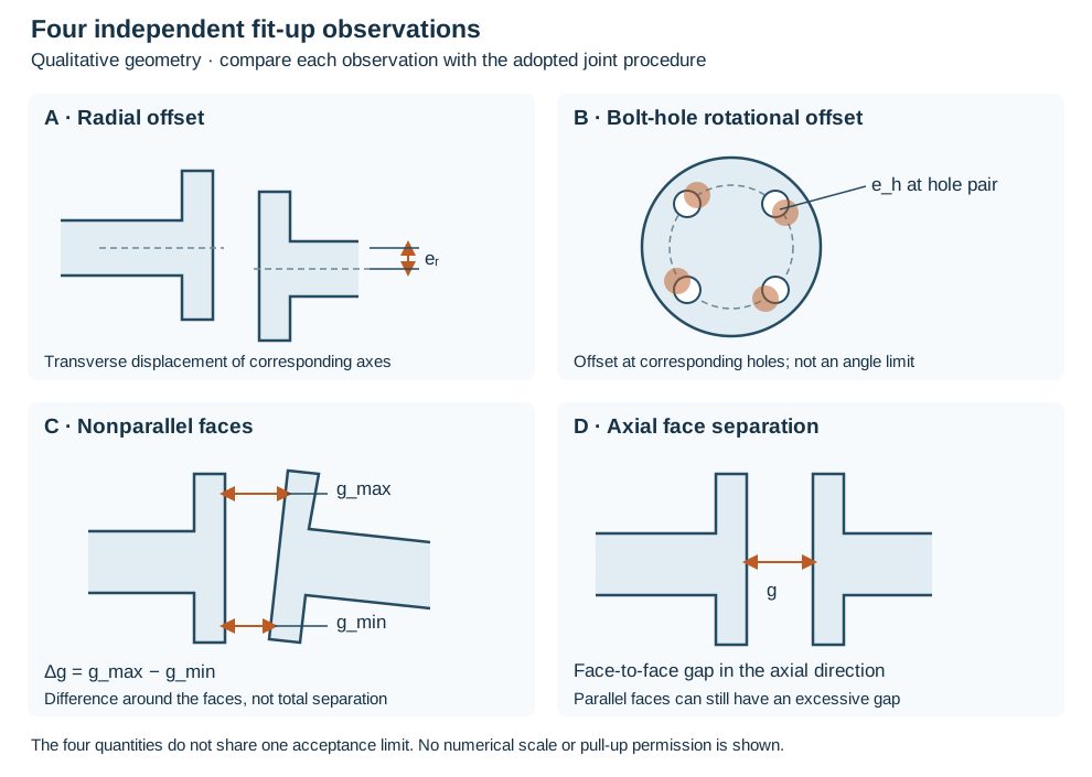
Figure 3.5. Radial displacement, bolt-hole offset, face-gap difference and axial separation are separate observations. The geometry is qualitative. The selected local criteria and excessive-gap investigation rule remain those stated above. Structured measurement relationships.
Measure bolt-hole displacement at the actual corresponding holes; it is not a specified rotation angle. Record the widest and narrowest face-gap locations on a common measurement basis. Parallel faces can still have excessive axial separation. Neither freely entering bolts nor a small gap difference establishes all fit-up conditions. Carry the observed geometry, permitted correction and verification into assembly and records.
The assembly procedure must define compatible fasteners/gasket, permitted lubricant surfaces, tightening stages and gap/alignment checks. Crossing passes distribute initial compression; later passes address bolt interaction. One adopted sequence uses crossing passes at 30%, 60% and 100% of prescribed final torque, then two circular passes at 100%. It neither selects final torque nor applies to every joint or tightening technology.
Relaxation after assembly can reduce retained load. An adopted procedure can require a later pass after a specified resting interval for defined equipment joints, while applying different follow-up requirements to piping joints. Keep the type of joint, interval and service conditions with that instruction. Do not infer that every assembled flange should be retightened after the same time, or that tightening during pressurized operation is an ordinary extension of assembly.
Cast-iron, plastic and FRP flanges, isolation kits, lap joints and equipment closures require their specific load and assembly treatment. An isolation kit combines sealing with an electrical-isolation function. Sleeves and insulating washers are part of that arrangement. Bolting that preserves containment but bridges the intended insulation has not achieved both functions. A soft or nonmetallic component can be damaged by load tolerated by a steel assembly. Construction carries the selected assembly into field work and Testing and readiness establishes the boundary, proof and restoration.
Keep the measurement setup, circle and acceptance basis together

Figure 3.6. Flange measurement circles and individual-plane policy.
Parallelism observations compare face gaps at equal distances from the centerline. Record the measurement circle with the widest-minus-narrowest difference. A difference taken at the outer rim cannot be compared directly with a limit defined at a smaller raised-face diameter. Lateral displacement of flange centerlines and bolt-hole orientation remain separate observations. Neither is the face-gap difference.
One adopted alignment procedure first requires bolts to enter freely. It then inserts the gasket and 25% of the bolts, with at least four. Those bolts are uniformly fastened with manual spanners only to remove free slack. That state establishes its general preassembled measurement.
It does not authorize pulling strained piping into alignment or replace the torque and investigation conditions above. Its rotating-equipment check instead uses loosely inserted bolting and its separate equipment criteria. Preserve the specified state in the measurement record. Substituting the general gasket/slack-removal setup would change that check.
The adopted procedure distinguishes two parallelism bases:
| Flange construction |
Paired-face criterion and measurement reference |
Consequence |
| ASME B16.5 construction in this route |
2.5 mm/m at the actual measurement-circle diameter |
Convert the slope quantity to a gap difference on that circle; rim tables use the corresponding rim diameter |
| ASME B16.47 construction in this route |
1.75 mm absolute at the raised-face outside diameter |
A value measured at the larger flange rim needs the specified rim conversion, with its size, class and series |
These are historical adopted alignment criteria, not a statement of current standard tolerances. For planar face tilt, the difference scales with the diameter of the observation circle. Let D_m be that diameter in meters. In the B16.5 route, M = (2.5 mm/m)D_m.
Before using a rim-table value, resolve its criterion and units: the accompanying historical table headings use a per-diameter unit while the raised-face instruction states an absolute gap. Establish a consistent criterion, circle and table rather than silently changing a unit. These criteria do not replace the earlier local radial, hole-offset or gap limits.
A terminal flange on an individual spool is compared with its design plane before its mating part is present. A selected policy permits an individual departure of (M/2)√2, approximately 0.7071M, stated in rounded form as 0.7M. That policy relies on a statistical possibility that eventual mating departures may compensate. It is not a deterministic guarantee that every permitted pair meets M.
Worst-case accumulation answers a different question. If two independently bounded departures must guarantee a combined maximum M, their adverse sum must fit M. Allocating M/2 to each is one equal allocation under that specific two-term model. Do not use the statistical 0.7M policy as that worst-case allocation. Terminal datums and dimensional closure carries the actual design planes and accumulation method into spool manufacture. The structured measurement relationships and teaching cases preserve the reference circles, setup and differing evidence claims.
Preserve the distinct assembly configuration
An electrically isolating joint can conduct through the central gasket, through a stud touching either flange, or through an incorrectly assembled washer stack. Sleeves separate studs from the flange holes. Insulating washers separate the steel load-bearing parts at the nuts. Verify the actual stack and the intended electrical isolation as well as containment.
A selected kit combines one central gasket with sleeves, insulating washers and steel backup washers. Another adopted construction uses sealing gaskets on both sides of its central insulating gasket. Those configurations must remain separate. Adding or deleting a gasket changes sealing, bolt engagement and stack dimensions rather than simply improving insulation.
The temperature limit belongs to the assembled kit. For example, one selected kit's gasket, washers and sleeves are limited to 392°F, or 200°C, while its nonconductive anti-seize has a much broader stated application range. The lubricant's upper temperature does not extend the kit limit. Compatibility with oxygen, oxidizers, acids and other reactive service also requires the actual lubricant/material basis, not merely an electrical-resistance label.
HDPE and FRP joints demonstrate a different limit on bolt loading. A selected HDPE procedure uses the manufacturer's gasket-specific torque and pattern. It repeats tightening at least one hour after first tightening and at least four hours after the second. It follows the changing assembled condition over time. It is not a universal retightening interval for nonmetallic piping.
An FRP torque table based on a stated bolt stress cannot be replaced by the steel-bolt table merely because diameter matches. Observed flange flexing requires disposition, not continued loading until the wrench reaches a larger target. The material qualification in Materials and construction account in Construction carry those system and installation checks.
Equipment closures preserve another history. In a selected sour-service floating-head basis, an existing retrofit with B7M fine-thread bolting retains that thread form, while a new floating head uses a separately specified coarse-thread arrangement. The respective torque tables use their own effective thread area and lubricant basis. That internal construction omits washers. An external flange's washer arrangement is not carried inside by analogy. Keep the actual material, thread form and maintenance configuration with the exchanger in Equipment arrangement and its records.
Air-cooler header plugs also use a different description from a flange stud. Their selected torque depends on the nominal threaded plug diameter, header/plug material and gasket construction, not wrench-head diameter. A soft-iron gasket and a graphite-faced profiled gasket can have different torque settings at the same thread size. The facing needs protection during installation.
A selected instruction threads the new gasket onto the clean plug instead of pushing it over the threads. Lubricate the specified header threads while protecting the gasket-seating faces. A plug that does not run in by hand needs a qualified thread-condition decision. Greater tightening effort or automatic thread chasing does not establish restoration.
These are equipment-specific assembly conditions, not a new general flange torque table.
External valve leakage has its own mechanism
Packing seals around a stem or shaft that must move. Compression loads the packing against the stem and box. Too little effective load permits leakage. Too much can increase friction, hinder movement or damage the assembly. Stem finish, straightness, corrosion, packing-box condition, gland alignment and the way rings are installed all affect performance. New packing in a damaged box is not necessarily a repaired seal.
A selected backseat can provide another stem-sealing contact near the fully open position. That contact changes a possible path toward the packing. The body and connected line can remain pressurized. The presence of the feature or the valve's wide-open position does not establish its leak-free condition, a complete isolation boundary or a permitted repacking intervention. Preserve the actual valve design and verified work state; Intervention develops the applicable preparation and limits. A statement about one valve's backseat cannot be applied to every bonnet or stem construction.
Manual block valves can remain at one position for long periods. Control valves continually move to regulate the process. Packing friction that is tolerable in one duty can create hysteresis or inadequate actuator force in the other. Changing from a low-friction packing to graphitic packing can therefore require an actuator reevaluation. This is a hardware/control interface, not merely a choice of emissions material.
Graphitic, fluorocarbon and combination packing systems provide different chemical, temperature, friction and fire-related behavior. Live loading uses springs, commonly disc springs, to maintain packing load as the packing consolidates or wears. It does not repair a corroded stem or make an incompatible packing suitable. Correct ring-by-ring installation can be important because compressing a stack inadequately can leave voids below a loaded top ring.
A bellows seal replaces the moving packing interface as the primary fluid barrier while it remains intact, often with backup packing. It can reduce external leakage but adds fatigue, cleanliness and replacement concerns. A claim of zero leakage must include the condition of that barrier and the duty for which it was qualified. It is not a permanent property of every operating state.
When leakage is observed, identify whether it is from the stem, bonnet, body joint, end connection or through the closed seat. Controlled adjustment under an applicable procedure, repacking, reconditioning and replacement address different causes. Repeated overtightening can damage a flange, gasket or packing and increase leakage. Online sealing or other temporary intervention has its own preparation and limits in Repair and modification. It should not become an assumed substitute for a maintainable valve. Operating integrity develops monitoring, condition assessment and intervention sequencing.
Install the packing as a defined set
Packing removal opens a fluid barrier and requires the isolation/depressurization basis in Intervention. Inspect stem, box, gland and follower before selecting replacement. Corrosion, scoring, misalignment and unsuitable box geometry cannot be repaired by a lower-emission packing alone.
Identify the required ring material, dimensions, arrangement and installation method. In a selected flexible-graphite construction, braided end rings contain the die-formed middle rings and wipe the stem. A deep box can need a specified bushing, spacer or lantern-ring arrangement rather than additional packing rings. Compression applied at the top may not reach the lower rings adequately.
PTFE and combination constructions have different arrangements. The graphitic end-ring recipe cannot be transferred to them. Chemical compatibility, temperature and fire duty remain part of the selection. In particular, graphite's usefulness in many hydrocarbon duties does not establish compatibility with strongly oxidizing chemicals.
The selected ring construction controls installation access. Unsplit die-formed rings can require disassembly; a field-split route must be permitted for the actual product. Staggered splits avoid a continuous leakage path through an eligible split-ring set.
Keep ring compression separate from stack compression
Use the manufacturer's instructions for the selected packing. Where a specifically adopted hand-operated-valve procedure uses the following fallback, it distinguishes three operations:
- Die-formed ring precompression: as each ring is installed, use the gland and spacer to compress it by 2–3% of its original height. This establishes contact through the depth of the set.
- Completed die-formed stack compression: after installing the full set, compress the stack by 20–25% of its original reference height. The denominator is the stack height, not one ring's height.
- Braided graphite set compression: under its separate five-ring route, install the first four rings. Tighten until resistance is felt. Install the fifth ring. Compress the completed set by 30%. This is not the die-formed precompression sequence.
Keep the reference height and stage with each percentage. Do not add percentages with different denominators or silently multiply successive reductions against a new reference. The actual procedure must establish the height used to set and verify its compression. Product-specific ring and set instructions can differ from this fallback, and an automatic control valve retains its separate friction, actuator and packing requirements. A higher compression is not automatically a better seal.
Structured compression method preserves the separate stages and reference heights.
A manufacturer can instead specify gland-bolt torque to obtain the required packing condition. Use that torque with its actual bolt, gland and packing basis. The flange-stud model above does not select it. The selected readiness procedure must verify stroke and leakage under the prescribed state, with any permitted adjustment followed by renewed observation. Retain installed-set identity and its height or torque basis in records; repeated tightening can increase friction or damage packing.
Keep packing research tied to the tested assembly and service
Transfer packing results only where construction/formulation, ring set, compression/torque reference, stem/box condition, motion, fluid, pressure, temperature and leakage measurement represent the intended assembly. Ambient methane comparisons on new identical valves do not qualify worn valves in hot service. Historical studies found corrosion and stem finish influential; experimental finish/clearance levels are not manufacture tolerances.
Cycling increased emissions for most tested packings, and retightening generally improved measured response. No tested packing achieved zero measured emissions. Field comparisons need service severity and sample size: the highest reported medians were in the 700–1,050°F and 450–1,010 psig group. A ppm screening concentration is not an annual mass leak rate without the measurement/conversion basis.
The laboratory chart's “100% compression” label supplies no absolute height reduction or installation schedule; methane pressure and exact cycle count are not given. An ambient packing-pressure chart has a clipped protocol note and cannot supply a numeric gland-pressure selection method. Structured historical research populations and limits retain these evidence boundaries.
Graphitic packing service compatibility is a separate gate. The historical incompatibility list includes strong oxidizers and specified conditions such as contaminated chlorine, oxygen above 600°F, phosphoric acid above 85%, sulfuric acid at 50–96%, fuming sulfuric acid and particular peroxide descriptions. It also lists butane/phosphoric-acid and sulfuric-acid/alkylate mixtures. These are listed exposures, not an exhaustive positive rating for everything omitted.
Several legacy chemical names or spellings and percentage conventions need actual substance identity established; a synonym cannot silently become a new concentration criterion. The structured companion retains the complete literal list and its qualifiers. Water service also raises graphite/metal galvanic-attack concerns. A favorable emissions test cannot remove them.
Pressure changes can damage gas-loaded soft seals
Gas absorbed into an elastomer can expand during depressurization, causing swelling, blisters and internal cracks (rapid gas decompression, also called explosive decompression). CO₂ is important in the reported applications; chemical attack, hardening, abrasion and thermal aging can coexist with that damage.
The seal must therefore be selected for its pressure history as well as its steady operating state. A body O-ring can remain stationary while a stem seal moves, yet both can become gas loaded. Dynamic seals generally have greater susceptibility in the reported comparison. Motion also introduces friction, wear and changing contact conditions.
Cross-section size matters: a reported distinction identifies seal cross-section diameters above 0.15 inch, or 3.81 mm, as generally more susceptible than smaller sections. That is the thickness across the sealing section, not the outside diameter of the complete ring. It is a susceptibility observation, not a guarantee for smaller seals or a universal size prohibition.
The assembly changes the result. Clearance, confinement and available extrusion paths affect how the seal can expand and retain contact. A design that limits expansion and avoids an extrusion path can perform differently from another design using the same named elastomer. Changing the seal compound without assessing its installed section, groove, clearances and movement can leave the damaging mechanism in place. Conversely, success with one confined assembly does not qualify the compound in every larger or moving seal.
Interpret a service history as an assembly history
A polymer family name does not fully identify a seal. Formulation, cure, hardness and actual manufacture affect its response. A reported sensitivity grouping can help identify questions, but individual formulations can perform better or worse than the grouping suggests. Temperature capability, oil and water compatibility, abrasion resistance and the required sealing motion remain simultaneous selection conditions. Greater decompression resistance is useful only in a compound and assembly that still performs those other functions.
Table 3.3. Reported CO₂ service histories illustrate qualification boundaries. Pressure reference and percentage basis are unspecified in these reports. The conditions are observations, not design limits or permission to substitute materials. Structured cases and qualification method.
| Reported duty and conditions |
Observed outcome |
Decision the observation supports |
| Oil production; 4,000 psi, 12% CO₂ in associated gas, 200°F |
Very few decompression incidents |
Preserve the fluid and operating history. “Few” does not establish immunity for all oil-production equipment. |
| Gas injection; 4,000 psi, 12% CO₂, 300°F |
A 70-durometer fluoroelastomer compressor seal failed. A 90-durometer formulation of that family or another reported fluoroelastomer operated satisfactorily with periodic replacement. |
The temperature, formulation, equipment and replacement duty belong to the result. The hardness scale and replacement interval are not given; greater hardness is not a general selection rule. |
| CO₂ production, pipelines and injection; 1,800 psi, 98% CO₂, 100°F |
Several named elastomers failed in some equipment, while other equipment using the same elastomers worked successfully under the reported conditions. |
Qualify the actual assembly and formulation. Family identity and nominal pressure-temperature conditions alone do not explain the different outcomes. |
A further pipeline history at 3,000 psi, 98% CO₂ and 100°F reports failures across the listed elastomer families while some assemblies using peroxide-cured compounds worked successfully. Assembly design was a major contributor. Another report at 4,500 psi, 98% CO₂ and 350°F describes the edge of the technology then being investigated. Neither report establishes a present universal material limit. The structured cases retain these additional distinctions without turning the histories into a compound catalog.
Do not calculate a CO₂ partial pressure simply by multiplying these reported percentages by the tabulated pressures. The pressure reference and composition basis have not been established. A valid partial-pressure input needs its own properly defined fluid and pressure basis. The low-pressure wording accompanying the reports also changes from “rarely” observing damage at or below 600 psi to a broader expectation of no problem. It does not supply a zero-risk threshold, especially for a different assembly or pressure history.
Qualify the decompression path and the maintained configuration
Qualification needs the actual pressure-versus-time trace, including pauses, fast portions and repeated cycles. An average fall rate does not establish these. Reported damage can occur after one or many decompressions; the histories supply no universal safe ramp or cycle count.
Qualify the proposed compound and equipment together, using high/low temperatures and pressures, defined fluid composition and CO₂/H₂S partial-pressure bases, pressure histories, seal cross-section, static/moving duty, groove/clearances, formulation, cure and hardness. Chemical compatibility, friction and wear remain simultaneous requirements.
Comparable operating history must include equipment geometry and maintenance/replacement duty; periodic replacement is not evidence for an indefinite-life substitute. New or materially different equipment/CO₂ exposure requires decompression testing on actual equipment before selection commitment, with stated conditions and acceptance. These histories supply no universal test protocol.
Carry the qualified compound, assembly and required replacement/depressurization basis into service selection, readiness, condition assessment and records. Substitution or changed pressure history reopens the affected qualification.
Hub-and-clamp connectors trade compactness against service details
A hub-and-clamp connector uses tapered clamp surfaces to draw two hubs together. Assembly mechanically energizes a metallic seal ring. Its lips engage the internal hub surfaces, and pressure reinforces the sealing action. This differs from compressing a conventional flange gasket between broad faces. It can reduce size and mass in suitable high-pressure arrangements and simplify assembly where a large flange’s bolt access is difficult.
Distinguish rib capture from lip engagement
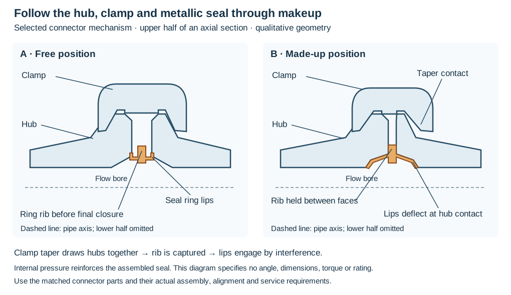
Figure 3.7. Selected connector mechanism in a qualitative upper-half axial section. The clamp acts on the external hub tapers. The ring rib is captured between the hub faces while its lips engage the internal hub surfaces. The drawing establishes the relationships, not manufacture dimensions or assembly settings. Structured parts and state relationships.
The clamp draws the hubs together through their outer tapers. The ring's central rib is captured between hub faces; its lips engage internal hub surfaces with interference and deflect to seal. Rib capture locates the ring and is distinct from lip sealing. Mechanical makeup energizes the ring before pressure reinforces it.
Use matched hubs, ring, clamp and bolts with the selected materials, pressure-temperature and assembly basis. Protect internal sealing surfaces during welding/handling and preserve the hub-weld metallurgy. Clamp closure cannot correct unsuitable alignment, damaged lips or mismatched parts. The qualitative drawing supplies no clearance, deflection or manufacture dimensions.
Compactness does not remove chemical vulnerability. Dead-flow areas around the seal ring can prevent an inhibitor from reaching a susceptible surface. For water-saturated sour gas, brine or other corrosive service with this mechanism, a connector selected for high-pressure sweet service can suffer localized corrosion and premature leakage. That contrary service recommendation belongs beside the connector’s benefits. Select another compatible connection or establish a substantiated service-specific basis. Pressure capacity alone cannot settle it.
A joint that leaks after correct tightening needs examination of the seal, surfaces, alignment and service damage. Increasing bolt torque indefinitely does not correct those conditions. Reuse of a seal ring is an assessment under the applicable connector procedure, with the cost and consequence of a failed test or renewed leak considered. Opening the connection requires established isolation and verified depressurization. A clamp can retain pressure even after its fasteners have been loosened. Removal of bolts is not evidence that the boundary is safe to open.
Jacketed assemblies contain two interacting systems
Jacketed piping carries product in a core and a heating or cooling medium around it. The core, jacket, spacers, terminations and component details must serve both containment and heat transfer. Their pressure-temperature conditions can differ, and their thermal movements need not be equal. A detail that transfers heat well in one arrangement can impose excessive strain in another.
Spacers maintain the annulus and affect the mechanical interaction between core and jacket. Terminations and connections can create cooler regions or different heat-transfer effectiveness. The heating medium must circulate through the intended jacket path. For liquid heating, an adopted arrangement introducing fluid at low points and removing it at high points helps fill the circuit.
For condensing vapor, high-point supply and low-point condensate drainage answer a different physical condition. Countercurrent flow and drainage slope are layout choices whose exact requirements belong to the selected system procedure. Utilities and Thermal protection develop the heating-system account.
The pressure boundary must also be checked during test. Testing the jacket puts external pressure on the core. A core designed for its internal product pressure may not withstand that differential. If and are the jacket and core pressures on the same reference basis, the pressure difference tending to load the core externally is .
The adopted test procedure can require core pressurization or a core wall capable of the jacket-test differential.
Test and examination sequence preserve access. A procedure that requires leak testing of the core with its welds visible before jacket closure cannot be satisfied by testing only the completed outside assembly. Later access is limited, so fabrication and inspection planning belong with initial selection. Jacketed flange designs can have pressure-temperature details different from an ordinary standard flange. Their designation alone must not be used to assign an unsupported rating.
Follow each boundary through the termination and local connection

Figure 3.8. Jacket boundaries, termination and local annular connection.
The core wall separates product from the jacket medium. The jacket wall and its termination contain that medium around the core. A jacket closure joins the outer boundary to the core while the product bore continues through it. A separable core flange or valve connection can interrupt the jacketed region without ending the product path. The selected local jumpover connects the adjoining jacket spaces around that interruption. Its seal and attachment are part of the jacket-medium boundary, separate from the core joint's gasket and bolting.
Spacers locate the core and maintain the intended annulus. The illustrated three-contact alternate leaves open sectors for passage and a specified clearance to the jacket. Use that alternate only when the engineering design or piping material specification calls for it. Its spacer material matches the core in that construction.
The contact, clearance, spacing, edge preparation and attachment affect both the passage and mechanical interaction. A convenient inserted piece cannot replace those requirements. Include spacer and termination effects in the movement analysis rather than assume the jacket and core can expand independently at every detail.
The local continuity panel uses one consistent condensing-medium arrangement: entry through the high jacket tapping, passage through the adjoining annular spaces and jumpover, and removal at the low drains, including the jumpover low point. Product direction is opposite the illustrated jacket direction. The drawing establishes connectivity and boundary locations. Slope, actual low points and drain construction must make that removal possible in the installed geometry. A liquid-heated arrangement with low introduction and high exit is a different state and routing basis. Do not apply the illustrated inlet orientation to it automatically.
An impingement plate near a selected steam entry and a siphon-tube drain for a selected vertical arrangement are separate construction alternatives. Fit either only where the selected detail and local physical conditions require it. They are not mandatory additions to every annulus, and a siphon tube does not establish drainage merely by being present. Likewise, a jumpover's tubing, nipples, couplings, insulation extension and any cleaned/seal-welded threaded region follow its specified jacket/valve size, material class and connection detail. Their catalog dimensions cannot rate another installation.
Retain separate core and jacket boundary/test states in the assembly record. Thermal construction, fabrication and readiness carry insulation, access and test/restoration interfaces. Structured boundary and connection relationships.
A flexible hose is a complete pressure-retaining assembly
A hose can accommodate movement, temporary connection or transfer where rigid piping is inconvenient. It is composed of a fluid barrier, reinforcement or metallic corrugations, protective layers and end fittings. Chemical compatibility of the inner barrier, temperature, pressure including surge, vacuum and movement duty must be evaluated for the assembled product. The tube’s rating does not establish that a particular coupling and its installation have the same capability.
Rubber hose, layered composite hose and corrugated metallic hose behave differently. Reinforcement carries pressure loads. The lining or tube provides the chemical barrier. A composite construction has layered barriers and end-sealing details whose service and installation limits deserve specific scrutiny.
Thin barriers and unreliable end sealing can defeat containment even when the individual layers appear chemically suitable. Where the adopted hydrocarbon-service criteria exclude composite hose because of such leakage experience, it is not an allowable substitute. A permitted vapor-recovery application is a different duty. Metallic hose can accommodate bending but its corrugations and braid have fatigue and movement constraints.
Do not infer that a metallic construction tolerates arbitrary vibration, twist or high-velocity flow.
Route the hose to maintain the specified minimum bend radius and protect it from kinking, crushing, abrasion and excessive end loading. Bending flexibility is not permission to twist the assembly. Supporting a hose badly can concentrate bending at a coupling. Lifting or dragging by a connection can damage the component that retains pressure thrust.
Vacuum duty needs suitable collapse resistance rather than a positive-pressure marking. Electrical continuity or intentional isolation also depends on the transfer arrangement. Bonding alone does not answer every ship-to-shore potential difference.
Built-in, externally swaged/crimped and internally expanded couplings retain hose by different constructions. Their compatibility and assembly procedures are consequential: an incorrectly selected or installed fitting can leak or separate below the hose tube’s rated burst pressure. Service qualification may therefore include the hose, fitting and assembler as one combination. Steam, LPG, marine cargo and utility hoses need their own qualification and operating limits. A cargo-hose rule is not a rule for every flexible hose.
Identification connects the hose to its construction, rating, history and inspection. Examine the cover, reinforcement where exposed, coupling, distortion and evidence of leakage or damage using the applicable procedure. Tests and inspection can support a condition decision but do not erase damage or establish an unlimited life. Keep cleaning, storage, handling and rejection requirements with the qualified service. Operating integrity carries the condition-assessment sequence, and Intervention carries replacement and return to service.
Preserve the joint’s duties when it changes
A component replacement can change far more than nominal size. New mass alters a branch or support load. Different face-to-face dimensions alter fit-up. Another seat or packing changes friction and leakage.
A different coupling changes restraint. A jacket or hose changes movement and test boundaries. Compare the actual substitute with the required functions and interfaces before installation.