Chapter 4 — Plant arrangement, access and constructibility
Arrange a working plant, not a collection of routes
Equipment removal, crane movement, valve operation, expansion and future construction require reserved space. Process connections, liquid head, gravity flow, pressure loss and proximity to utilities or transfer facilities constrain equipment placement.
Terrain, soil information, climate, drainage, transport connections and available land constrain the choices. A block plot plan can then reserve areas for process units, storage, utilities and waste handling in relation to one another. Its preliminary rectangles estimate functional areas. They are not final equipment clearances.
A process flow diagram establishes connections without establishing routes, access or supports. A three-dimensional clash check does not establish that an operator can perform the task.
Develop the area as a whole before finalizing each line. Routing the first connection in the shortest available path can occupy the corridor needed by several later connections. Additional bends, supports and elevations then accumulate around that early choice. A whole-area study can group routes by destination, preserve useful access and locate crossovers before the detailed arrangement becomes expensive to change. This does not require final data for every item at the outset. It requires awareness of which uncertain interfaces can alter the arrangement.
Spacing also serves containment of consequences. Separation between units can limit exposure to fire radiation or explosion effects and preserve emergency-response access. It can also permit maintenance or hot work in one area while a neighboring area remains in service. Greater separation can lengthen piping and consume land. Close grouping can increase exposure and congestion.
Compare those effects under the actual hazard and operating basis. Minimum spacing, convenient process proximity and adequate maintenance access answer different questions.
Some spacing bases group operations by their fire and explosion hazards to select relevant criteria. Such a classification does not replace hazard identification or analysis. Inventory, phase, pressure, temperature, unit size and interdependence can change the consequence of a release and the scope of the spacing decision. A distance copied from an equipment pair in another service can therefore miss the governing problem. Use the applicable spacing basis with the required hazard context. Do not treat a layout table as a universal safe-distance rule.
Escape to a designated safe area and evacuation from the installation need paths, destinations and capacity appropriate to the facility and personnel. A release, fire or obstruction can invalidate a routine passage. Coordinate safe support facilities and response access with the site hazards.
Plan and elevation solve different problems
A plan view establishes equipment relationships, corridors and branch destinations. Elevation establishes headroom, gravity paths, equipment nozzles, pipe layers and platforms. A route that looks clear in plan may collide with a beam or lack the elevation needed to drain. A workable elevation may still obstruct a passage or withdrawal area. Review the two together rather than resolve one and assume that the other will follow.
Consistent routing elevations simplify the installation. Several unnecessary levels can require additional support steel and obscure which line crosses which. Grouping compatible routes at common elevations can reduce that complexity. Elevation changes remain justified where they preserve drainage, process head, equipment movement, access or the ability of another route to cross. The purpose is orderly physical behavior, not a rule that every line must remain in one layer.
At a rack or corridor junction, line sequence matters. Flat turns preserve a sequence of adjacent routes: a line on the outside can turn away before a line toward the center. If their destinations require the sequence to change, a crossing or another elevation may be needed. A long diagonal at the same elevation can block many adjacent routes, whereas a short local offset may cause little interference. Judge the effect on the other lines and on future connections. Do not select a diagonal solely because it saves one fitting.
Future expansion can reverse the preferred arrangement. A flat turn that is satisfactory at a dead end may obstruct a future through-route. An inexpensive elevation change during initial design can preserve that corridor. Conversely, raising every line in anticipation of unspecified expansion can add support and access burden without a useful purpose. Identify the probable future equipment, connection and reserved space, and record what the arrangement is preserving. Future allowance should represent a defined opportunity, not unallocated empty space that later detail design quietly consumes.
Equipment elevations require their own physical basis. A higher vessel can increase liquid head or accommodate gravity flow, while also increasing structural height, access and lifting requirements. A vertically structured arrangement can suit process and land constraints but creates several working levels and removal paths. A grade-mounted arrangement can simplify mobile maintenance while using more site area or longer connections. Rotating equipment and vessels, heaters, exchangers and storage develop the particular process and equipment mechanisms. The common layout method compares the resulting elevation, access and construction consequences without replacing those mechanisms with one preferred plant shape.
Carry a routing choice through its present and future configurations
Start an area study with a connection list: each line's origin, destination, service and required route conditions. Group equipment that performs a related process function. Then examine the connections within and between those groups.
A process-flow symbol can represent several exchanger shells and can omit utility equipment; the equipment list and preliminary outlines therefore complete the physical population. Identify large, alloy or heavy-wall connections early because their loss, stiffness, weight and cost can make equipment placement consequential. The process sequence suggests proximity, while head, safety, support and maintenance can require a different arrangement.
Lay out the group before resolving one convenient connection. For parallel lines serving equipment on one side of a corridor, the outer destinations can often be reached by peeling off the outer lines first. Central destinations are then reached without crossing those departing lines. If that order cannot serve the actual destinations, compare a changed line order, equipment position or crossing elevation. The useful evidence is the whole set of connections in both plan and section. Counting bends in one line conceals the space and supports it demands from its neighbors.
Figure 4.1 isolates one consequence. The current line A reaches a destination south of the corridor. With no eastward through-route required at that station, its turn can stay at the common level. A defined future line B must pass eastward at that level. Its plan path intersects A's departure.
The two lines carry separate connections: the intersection is neither an intended tee nor an available empty lane. Keeping the turn flat would consume the identified future route.
An alternative changes A's elevation before it crosses B's lane and restores the required destination level afterward. The plan footprint still overlaps, but the section now separates the two envelopes. The drawing identifies only that topology; the raised level has no assigned height. The required separation must include actual pipe, insulation, flange and movement envelopes, together with the selected support and access arrangement. A drainage requirement, insufficient headroom, a nozzle condition or an unsuitable movement path can defeat this alternative. Moving the departure or equipment, changing the corridor sequence, or assigning the future line another evaluated level may be preferable.
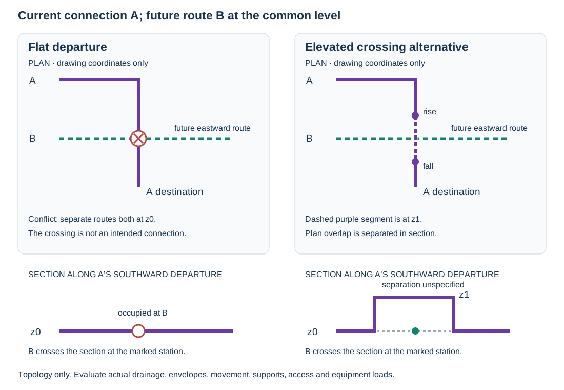
Figure 4.1. An authored topology example derived from the area-routing method. A flat departure connects the current terminals but occupies the future line's common-level path. A locally elevated crossing separates the routes in section. Drawing coordinates are schematic, with no dimensions, loads or clearance acceptance supplied. Structured geometry.
Without the future route or another crossing need, the rise and fall add fittings, supports and installation work. Preserve the identified line and level only where the requirement warrants those additions. Large or stiff connections also require support and equipment-load evaluation.
A valve manifold offers the same reasoning at a smaller scale. A sequence of reducers can sometimes be replaced by appropriate branch connections, reducing the number of separate fittings and shortening the assembly. That alternative changes the joint and branch construction. The selected piping class must permit it, and valve access, support, inspection and assembly must still work. Fewer drawn fittings do not establish an acceptable branch or a lower lifecycle cost by themselves. The route and manifold comparisons both select complexity by the function it preserves.
Revise the whole equipment group against the routes it must serve
A layout study carries equipment and connection identities through functional grouping, an initial plan, a line-run check and revision. Check gravity-flow elevation, alloy-route length, servicing/handling space and furnace separation/wind relationships.
The four panels below use an explicitly hypothetical equipment population and drawing geometry. D is a feed drum, P its pump, E a feed exchanger, F a furnace and R a reactor. C1 and C2 are compressors. V is a liquid-collecting vessel feeding exchanger G by a selected gravity route.
The process connections and identities remain constant across the panels. The example combines several layout constraints in one comparison. Its coordinates are drawing units, not plant dimensions, distances or approved equipment positions.
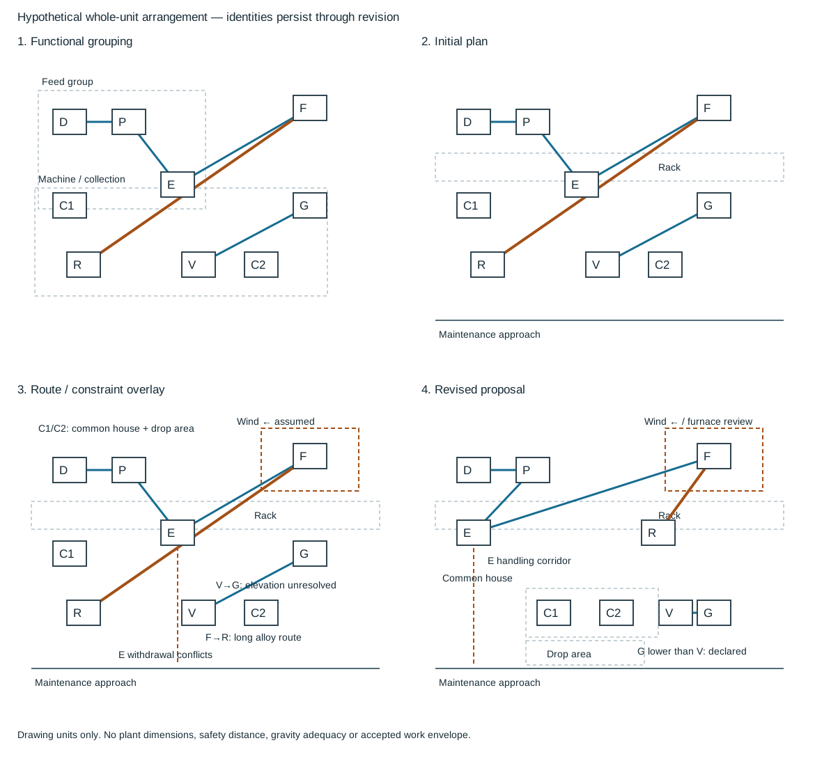
Figure 4.2. Panels 1–4 keep the same equipment and process connections. The overlay names the requirements that cause the revision. The revised panel marks their proposed spatial responses. Plan proximity does not establish gravity head, furnace separation, adequate withdrawal clearance or a qualified alloy route. Structured equipment, routes and revision causes.
The initial plan separates the compressors and puts the reactor across the rack from its furnace connection. Exchanger G is beside V without an elevation commitment.
The constraint overlay makes five questions explicit. First, the V-to-G route needs its selected available head and draining geometry. Thus G's elevation must be resolved with V's liquid level and the actual losses. Second, E needs its axial bundle-removal and handling path.
Third, C1 and C2 are assumed to require a common operating and servicing house with a drop area reached from the maintenance approach. Fourth, the F-to-R connection is assumed to be an alloy route whose unnecessary length matters. Fifth, F needs its adopted separation and wind relationship to the unrelated hydrocarbon equipment. The wind arrow is an assumed teaching direction, not a site meteorological study.
The revised plan groups C1 and C2 along the maintenance side and reserves a connected drop area. It moves E so its withdrawal path reaches that side. It brings R nearer F to shorten the selected alloy route while keeping the furnace-separation review visible. It also assigns G a declared lower elevation relationship to V for the gravity route, rather than representing elevation by plan spacing. These changes are proposed responses to the stated constraints. Neither the shortened alloy connection nor the gravity arrow supplies the pressure-loss, flexibility, support or safety evidence needed to accept the result.
| Revision cause |
Proposed response in the worked comparison |
Consequential verification |
| Gravity flow from V to G |
Preserve a declared lower receiving elevation and a draining route |
Actual liquid level, pressure, losses, nozzle reference and operating range |
| Exchanger E servicing |
Turn the removal corridor toward the maintenance approach |
Bundle and cover envelopes, lifting/handling, disconnected piping and support states |
| Common compressor servicing |
Group C1/C2 and reserve a connected drop area |
Actual house, crane/handling path, equipment removal and operator tasks |
| Alloy F-to-R route |
Reduce unnecessary separation and route length |
Material/service basis, thermal movement, equipment loads and supports |
| Furnace exposure and wind |
Retain the selected furnace zone and prevailing-wind relationship for review |
Adopted safety spacing, site conditions, related/unrelated equipment distinction and access |
Changing one position can reopen several interfaces. Moving R closer to F may shorten alloy pipe while consuming access or changing exposure. Elevating or lowering G changes structure and work levels as well as head. Grouping compressors can share handling facilities while making one removal task interfere with another.
Carry the selected equipment locations, elevations, connection list and maintenance requirements into technical continuity.
Preserve line identity through turns and shared entry corridors
A rack turn must preserve the connection identities as well as a usable section. In the three-line example below, L1, L2 and L3 arrive in a declared order. A flat set of nested turns preserves their order along the departing rack when read in a consistent local cross-section direction. If the destination arrangement instead demands the order L3, L2, L1, the line identities must be traced through that permutation. Assigning a label to the nearest drawn line after the turn would silently change the connection list.
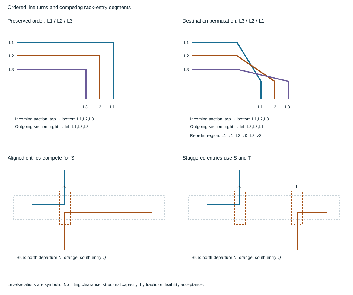
Figure 4.3. The first pair compares a preserved line order with a separately declared destination permutation. The permutation lists each line's selected level through the reorder region. Plan intersections remain separate lines. The second pair compares two entries competing for one occupied segment against entries at separate stations. Station shift and levels have no assigned physical separation. Structured line identities, order and occupied segments.
Use the existing plan-and-section crossing account to evaluate a changed sequence. A level assigned through a reorder region is an interface requiring actual rise/fall geometry, fitting and insulation envelopes, drainage, thermal movement and support checks. Another solution can change the destination order or move the connection station. The diagram keeps L1, L2 and L3 bound to their destinations while those alternatives are compared. It does not establish the level heights or mechanically adequate routes.
Opposing rack entries have another constraint. A branch departing toward the north can occupy the same entry segment that a secondary rack from the south needs to reach. Aligning their structural centerlines may look orderly while leaving no independent route through that segment. In the comparison, the north departure and the south entry initially compete for segment S. The alternative places the south entry at another station and gives it segment T, while retaining both connection identities. A station shift can resolve this particular shared-corridor conflict without being a rule that every secondary rack moves one bay.
Inspect the occupied entry segments, the lines turning or rising there, and their support and future-route spaces.
A changed station changes line length, support positions and possible crossings elsewhere. The actual bent spacing and available width determine whether the shifted approach fits. The structural rack centerline does not reserve the pipe envelopes automatically. Confirm those relationships in the congested sections developed under rack route planning.
Name the point and datum before comparing elevations
A location should identify the physical point, coordinate datum and units. Bottom of baseplate, vessel centerline, bottom of saddle and top of steel are different points. A shaft-center elevation cannot substitute for a baseplate elevation without the intervening equipment dimension. Likewise, a height above local grade is not automatically an elevation on the project datum.
Coordinate labels must retain their assigned datum: an English project datum of 100 ft and a metric datum of 100,000 mm are independent conventions, not a unit conversion. Compare physical separations within one convention or through an explicit datum mapping.
An offsite height above the high point of grade requires the applicable grade elevation before comparison with an absolute project elevation. Do not replace grade with a separately scheduled paving high point. Preserve grout allowances and the interfaces included in support or baseplate elevations.
The physical selection remains a coupled decision. Suction head, oil return, pulsation-bottle clearance, operator access and maintenance can govern different equipment points. Where independent lower bounds refer to the same point and datum, their maximum is the least elevation satisfying them all.
A preliminary sketch labeled with a suction-head height is a layout input. Available NPSH also requires liquid pressure, vapor pressure, operating level, losses and the selected pump reference. Use the suction-head account and equipment interfaces to establish those demands before deciding which bound governs. Changing the route or equipment can change the bounds and should reopen the comparison.
Develop the pipe rack from the routes it must carry
A pipe rack combines piping with structural support and often cable trays, utilities and equipment. Its width, levels, elevations and bent spacing therefore depend on several interacting uses. A bent is the transverse structural arrangement that carries the rack at a support station. Longitudinal members can stabilize the structure and provide intermediate support or support for routes entering and leaving it. Their spatial positions need coordination with both the piping and structural design.
Start with a line-routing diagram on the plot plan. At this stage it shows which lines traverse each part of the rack and where they enter or leave. Exact offsets and interferences can remain unresolved. The diagram identifies congested stations. Develop a dimensioned section through those stations using line sizes, insulation, fittings, movements and required working clearances.
A count of lines alone cannot establish the width. A small line, large insulated line and line with a flange or valve occupy different envelopes.
Process piping is often grouped on lower levels with utility piping above it. Cable trays occupy a coordinated upper level or a separate level. This is a useful arrangement to examine, not a substitute for the actual service and access requirements. Electrical and instrument participants need to define tray space before the rack layers are fixed. Gravity or relief routing, equipment connections and process demands can require a different local arrangement. Keep overhead tray, pipe and equipment envelopes visible in the same section.
A simple packing calculation illustrates how a cross-section method works. Let be the effective outside envelope of line at the section. The required clear gap between adjacent envelopes is . The edge allowances are , . All are measured in the same length unit. For an ordered row without overlapping envelopes,
This is a geometric accounting identity. The engineering work lies in defining the envelopes and gaps. Insulation increases the outside envelope. A flange, valve operator, movement or removal task can govern a local section instead of the pipe body. The edge allowance must reflect its actual interface. A structural column, an adjacent layer or a reserved route is not free space merely because it lies outside the first pipe.
Reserve future capacity under the adopted planning basis and keep it distinct from present uncertainty. One rack-layout basis provides an additional 20% of space for future growth.
Where that basis is selected, preserve the allowance and its meaning in the rack arrangement. Define whether the allocation is a particular width, lane or level. Verify that branches, crossings and structures keep it usable. Do not silently reinterpret a space allowance as structural load capacity. Do not count the same space for unknown present lines and committed future lines.
Bent spacing addresses a different dimension. The pipes need acceptable spans in their relevant material, contents, temperature and insulation states. A structural column spacing does not automatically establish a suitable pipe support spacing. Road crossings or underground obstructions can require larger column gaps. Intermediate pipe bents or longitudinal support members are possible alternatives, subject to structural and pipe evaluation.
Support and restraint decisions develops the weight paths and mechanical states, while flexibility and loads develops the analysis. The layout must leave room for the selected supports and expansion arrangements. Fixing the corridor first can leave an impossible geometry that analysis cannot recover.
Access is a task and a path
Clearance between two objects does not by itself establish access. Identify what the person or maintenance equipment must do, from approach through completion and removal. Reading a gauge, operating a valve, opening a manway, withdrawing a filter element and lifting a compressor component require different spaces and positions. Include tools, component travel and the place where a removed item is handled, not only the body of the person at the equipment.
For routine operation, locate controls and indications so the intended work can be performed from the selected access position. A valve handwheel that is visible across a pipe is not necessarily reachable with the required motion. A chain operator needs a clear hanging path. A local indication may need to be visible while a related control is adjusted. Elevated work can require a platform, stair or ladder according to the task, frequency and governing access basis. The presence of a ladder does not establish a suitable position for every maintenance job.
Instrumentation and control develops the measurement and control functions that these locations must preserve.
Maintenance adds larger envelopes. A heat-exchanger bundle needs a withdrawal corridor. A vertical pump or turbine part needs overhead removal space. A control-valve actuator may require access above it even when the valve body stays in place. A vessel manway needs room to open or remove the cover and support associated work.
The specific equipment chapter supplies the dimensions and removal mechanism. Layout keeps the path available through the surrounding installation.
A lifting path continues beyond the first vertical movement. A removed part must clear obstructions, travel to a laydown or transfer position and reach the transport or repair arrangement. For mobile equipment, consider approach, setup position, boom or swing clearance and the route out. For a fixed lifting arrangement, consider its travel and the load-transfer positions. Hydrants, lights, overhead lines, cable trays and later small piping can obstruct a path that appears clear when only the major equipment is drawn.
Compact placement can reduce lifting reach but increase congestion. A permanent lifting facility can simplify repeated maintenance but adds structure and interfaces. A temporary arrangement may be appropriate for infrequent work where the actual job and access permit it. The choice needs the part weight, removal procedure, frequency and available handling equipment. Do not turn a historical manual-handling number or crane-road dimension into a universal current limit. The useful method is to define and compare the complete task with its equipment and constraints.
Access also has a hazardous operating context. When another feasible arrangement removes the exposure, avoid frequent lifts over operating process equipment. Where the adopted layout basis permits an alternative protective arrangement, its purpose and extent must be explicit.
The operating and maintenance state matters. A route available during a shutdown may not be usable while neighboring equipment remains in service. A maintenance envelope should state which configuration it assumes, including any piping that is intentionally removed and how the remaining assembly is supported. Operating integrity and maintenance and repair and modification carry that reasoning into intervention.
Build equipment spacing from the spaces that have different jobs
A center-to-center spacing can be developed from outside envelopes and intervening work spaces. Consider a horizontal drum beside an exchanger in a common transverse section. Let and be their effective diameters at the section, the clear operator-access strip, and the separately reserved piping-and-controls strip. With parallel, nonoverlapping strips and circular outside envelopes, their center separation is
All quantities use the same length unit. The half-diameters reach from the equipment centers to their nearest outside boundaries. The variables and then account for the clear space between them. This tower-area spacing model keeps operator access and piping/control space as distinct contributions. Actual projections, insulation and attachments must be represented by the effective boundary or checked separately. A bundle diameter alone can omit the channel flange that governs the adjacent section.
If a control valve or actuator grows into the operator strip, the original arithmetic can remain correct while the reserved function is lost. Increasing , reorienting the assembly or relocating the control are alternatives. Each changes a route, work position or support interface. A common strip can serve more than one task only when the assumed work states and sequences permit that sharing. It should not be counted twice as simultaneously available space. A regular operating passage and a shutdown bundle-pulling path may have different occupancy conditions.
The scalar sum also says little about vertical access. A platform can place the valve within reach while leaving a cover or filter withdrawal obstructed above it. An exchanger bundle needs its selected axial path and handling position. A vessel manway needs opening and work space on the correct side. Include the axial withdrawal, manway, cover and filter envelopes in plan and elevation, with the task and state, and follow the component through to laydown or transport.
Compressor cylinders illustrate another spacing model. One cylinder-removal arrangement defines removal length as the cylinder-removal distance plus a local allowance. The common gap between opposing tasks is plus another allowance. This is a task-length account rather than the circular diameter model above. Sharing an area between machines does not establish that both cylinders can be removed simultaneously or that adjacent equipment may remain operating during the work. The actual cylinder, handling method and intervention sequence determine how the common space is used.
For elevated equipment, reserve the connected path from lift-clearance through the maintenance area and drop zone to the vehicle or repair position at grade.
A clear operating deck does not establish that the ground-level route is available. If maintenance takes place on the deck instead, identify the item size, weight and supporting-floor basis. The selected lifted load and hook geometry also affect the crane and building envelope. Structural adequacy cannot be inferred from the outlined clear area.
This approach lets compactness be evaluated rather than assumed. An elevated arrangement may use less ground area while adding structure, access and handling interfaces. A common crane, condenser or working area may justify longer piping because it simplifies repeated operation and maintenance. A grade-mounted arrangement may permit mobile handling while using more land or removable overhead piping. Compare these arrangements through their process connections, work paths and relevant states, and retain the reasons for the selected compromise.
Structures organize work as well as support equipment
A structure can carry one or two items or much of a process unit. It may be open, sheltered or enclosed and may use steel or concrete. These choices affect equipment elevation, climate protection, access, lifting and installation sequence. Define the equipment and work requirements before fixing the frame, platforms and siding.
A frame that is adequate structurally can still obstruct a removal path. Bracing, beams, handrails and roof members need to be coordinated with manways, exchangers, instruments and lifting equipment. Removable sections can preserve a defined maintenance path, but their identity and removal/reinstatement needs belong in the arrangement and records. Openings left for a one-time installation should not be assumed to remain available for later maintenance if the final structure closes them.
Platforms should put the intended tasks within useful working space. Common platforms can serve several items and reduce separate access structures. Different elevations or process arrangements can make that solution unsuitable. Frequent operator attendance, occasional inspection and heavy-component maintenance are different functions. Choose the access arrangement and flooring for those functions and the applicable environment. Clearing the equipment outline alone does not justify a narrow platform.
Piping supports, fireproofing and structural details also occupy space. Fireproofing can enlarge a column or beam envelope and affect connections and clearances. Precast concrete members may occupy more space than an assumed steel frame. Supports for lines leaving a rack need actual attachment locations. Keep these interfaces in the model and installation information. An apparently minor late change to a brace or support can reverse the clearance on which a valve, instrument or removal path depended.
Shelters and enclosures require particular attention to maintenance. A roof can help the operating environment while limiting a lift. An enclosed structure may need a crane, designated drop zone or removable panel to handle equipment. Compare these configurations through the actual component path and selected handling equipment. Rotating equipment develops compressor case and nozzle arrangements; this chapter supplies the common method for evaluating their spatial and access consequences.
Choose who carries the added equipment and working structure
Placing an exchanger above a drum can provide the required gravity-flow relationship while leaving two distinct support choices. An independent frame carries the exchanger, platform and drum at their required elevations through structural members to the foundation. A vessel-carried alternative places the exchanger and platform reactions into the drum shell, with the drum itself carried on concrete piers. The process arrangement can look similar while the load owner changes completely. Before choosing the vessel-carried alternative, consult the vessel engineer. Shell and local attachments, saddles or piers, foundation and connected piping must accept the added dead, operating, test and access loads.
An independent frame changes the motion reference. Drum, exchanger and structure may have different thermal movement or settlement, which their connecting line must accommodate. Vessel-carried equipment may move more closely with the drum at its attachment. This does not eliminate relative expansion of the exchanger or the gravity-flow pipe. Evaluate both alternatives through operating, test and maintenance states, including exchanger removal and lifting. Reduced separate steel is a possible layout economy only after vessel/structure capability and the full installation and maintenance cost are established.

Figure 4.4. Separate schematic load-path alternatives for exchanger/platform above a drum. The gravity-flow connection and attachment construction are omitted. Actual relative movement, shell and frame capacities remain separate assessments.
| Alternative |
Added load path |
Movement and intervention question |
| Exchanger/platform on independent frame |
Equipment and working loads → frame → foundation |
Relative drum/frame/equipment movement; connected piping flexibility and removal support |
| Exchanger/platform carried by drum |
Equipment and working loads → local shell attachments → drum supports → foundation |
Local shell load and deformation; differential equipment growth; test and removal states |
| Coker penthouse/drill carried by drums |
Work-structure and piping loads → drum attachments/shell → drum supports |
Cyclic vessel movement and work loads; vessel design for the complete added duty |
| Coker work structure carried by elevated deck |
Work-structure loads → independent steel → deck/foundation |
Relative cyclic drum/structure movement and the pipe-support/flexibility interfaces |
The coker comparison is a separate cyclic-service application, not an enlarged version of the small drum/exchanger arrangement. In one alternative the penthouse and drill structure are carried from the drums. In the other the entire work structure is carried from the elevated concrete deck. The main operating-valve platform is deck-supported in both. Moving the drill load away from the drum may change required vessel wall and structural steel, but no thinner-wall result follows without vessel assessment.
Drum cycling makes relative movement and connected piping especially consequential in the independent arrangement. The work structure's operating, access and lifting duties require their own load basis and economic review. This comparison supplies no drilling or decoking procedure.
The load paths in the process-carrier example expose the same principle: assigning a component a second supporting role creates new reactions and movement constraints. Preserve who receives those reactions in the equipment specification and drawings. Later platform enlargement or equipment replacement then reopens the affected vessel and structural checks.
Nominal fit is not the ability to build
A drawing can show a geometrically correct connection that cannot be assembled economically in the field. Equipment and foundations have placement tolerances. Prefabricated spools have dimensional tolerances. Construction follows a sequence in which some interfaces are fixed before others. An arrangement that provides no practical adjustment or final connection can force rework even when its nominal geometry is sound.
A fitting-to-fitting connection illustrates the problem. If a vessel and pump do not arrive at their nominal relative positions, the compact connection can offer little opportunity to accommodate the difference. A deliberate construction spool can leave a controlled place to make the fit-up adjustment. The same issue arises at large equipment headers. The solution should provide an identified erection interface rather than rely on unplanned forcing of the connected assembly.
A construction allowance is not intentional cold spring. Cold spring introduces a specified prestressed geometry for a mechanical purpose. Field fit-up needs to preserve the accepted arrangement and equipment limits. If the adjustment changes the route, support contact or restraint behavior, reevaluate the affected interface. Fabrication and construction develops tolerances and assembly methods, and mechanical analysis and supports develop their mechanical consequences.
Construction sequence is itself a layout input. A central rack may need early erection and piping access before surrounding equipment makes the work difficult. Large modules, vessels and structures require delivery and lift routes. Temporary offices, storage, laydown, welding and assembly areas should not occupy the only approach to equipment needed during construction or maintenance. Coordinate the sequence and temporary facilities with the eventual installation. A workable final plot does not demonstrate that every construction stage is workable.
Field-run small piping, lighting and cable trays deserve explicit installation guidance where they can affect work. Major-equipment models may omit these details. A late hose, branch or bracket can block an operator's position or a removal corridor without creating a major model clash. Construction verification should examine the physical tasks and paths reserved by the design, not only whether the installed item follows its own drawing.
Coordinate containment, drainage and the routes around them
Storage and spill containment reserve physical space for a function that is largely invisible during normal service. Tanks, dikes or secondary walls, drainage gradients, sumps, roads and transfer piping need to be developed together. A tank area can contain the required inventory geometrically but still have unsuitable access or an obstructed drain route. A piping crossing can defeat the intended boundary. Storage and containment develops containment forms and usable-volume sizing. Layout carries their placement, access and piping interfaces.
A compact concrete-wall arrangement and an earthen dike use space differently. The chosen form changes access across or around the boundary, the room for tank work and the route of product-transfer lines. Terrain can assist drainage while also constraining the enclosure. Under the selected service and drainage basis, decide where minor spills and rainwater go. Keep that path compatible with containment. Do not treat a convenient opening as an acceptable penetration without the required detail and service assessment.
Underground services share this crowded area with foundations, roads and rack columns. Gravity drains have an elevation requirement that pressurized routes may not share. Crossings and equipment foundations can interfere with both construction and later excavation or repair. Reserve the corridors and coordinate levels while the arrangement is still flexible. Buried piping, pipelines and offshore interfaces develops the distinct system engineering. A plant layout should not erase those distinctions merely because the routes share a site.
Emergency and routine access need to remain usable alongside these facilities. Place roads and work areas for their actual tasks and handling equipment. Preserve the relevant clearances around aboveground crossings. A nominally wide road loses function if a permanent obstruction occupies a needed setup position. An overhead route can also prevent the chosen vehicle or boom from passing. Evaluate the route as a connected path rather than a collection of local dimensions.
Verify the spaces the design intended to preserve
Record provisional dimensions and dependencies on vendor geometry or handling method. A change to either reopens the affected arrangement. Clash and envelope checks do not establish pipe spans, structural loads, thermal movement, valve removal or human access.
During installation, verify control position and operation, removal/lifting/laydown paths, erection connections and access around racks, structures and containment. Include field-run piping, lighting and trays absent from the model.
Changes can consume reserved space gradually. A new instrument, a larger actuator, added insulation, another cable tray or future piping may each appear small in isolation. Assess the combined effect on the function of the corridor or envelope. A space allocated to a withdrawal path should not become a convenient permanent storage area without addressing that consequence. Engineering records and human factors develops the task-analysis, configuration and feedback route that preserves these decisions through construction and operation.