Chapter 11 — Support and restraint decisions through the lifecycle
Carry the load while preserving the intended movement
A sliding shoe carries weight while allowing travel; a guide directs that travel, a stop limits one direction, an anchor fixes specified freedoms, and a spring carries weight through vertical movement. Near a nozzle, support can reduce weight moment while restraint increases displacement load. Select the carried loads and permitted movements together, with acceptable pipe, attachment, equipment and structural reactions.
The numerical support-selection criteria below apply to a defined aboveground metallic process-piping scope. They are drawn from criteria for ASME B31.3 metallic piping at temperatures of 427°C (800°F) and below, excluding cryogenic service below −101°C (−150°F).
Use those criteria only where the project adopts that scope. Cold-insulated piping still needs insulation and vapor-barrier treatment, while cryogenic systems need a separately established selection basis. For an application, establish the governing code edition, project criteria and equipment limits. The historical standards references discussed here do not establish present compliance.
The line has several mechanical states
Include pipe, fittings, valves/operators, lining, insulation and contents, including test liquid for vapor-service lines and project-required snow/ice. Concentrated masses can govern differently from uniform pipe weight.
Equipment movement, settlement, wind, seismic effects where applicable, relief reactions, water hammer and other mechanical loads can further change support demand.
Temperature must be described as a sequence of credible conditions, not a single operating value. Start-up, shutdown, steam-out or decoking, depressuring, regeneration and defined upsets can produce movement or displacement ranges that normal operation does not reveal. A parallel pump branch may remain cold while the header and neighboring branches are hot. Different branches can be cold on different occasions. A support scheme that accommodates every line at one uniform temperature may therefore miss the relative movement that governs a connection.
Installation creates another state. The pipe may be empty, insulation incomplete, springs locked and some equipment not yet connected. A vertical vessel may be fitted with piping while horizontal. Its attachments and guide brackets must therefore carry a temporary direction of gravity loading. Hydrotesting adds liquid and pressure, may isolate the line at temporary blinds, and may require temporary support or spring blocking.
The support system also changes when contact changes. A resting shoe cannot carry downward weight reaction through a support it has lifted clear of. Retaining that support as active in a sustained-load calculation creates a load path that no longer exists. Where thermal movement causes lift-off:
- Remove the lifted support from the applicable sustained-load representation; or
- Consider a spring that maintains the weight-support path.
Examine both hot and cold contact configurations.
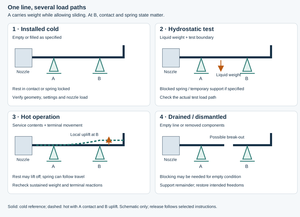
Figure 11.1. A conceptual state model for one equipment-connected line. The upward movement in operation is an assumed example, not a prediction for every line. Support A is a sliding rest. Support B is either a rest that can lose contact or a selected spring.
The test and maintenance configurations require their own load-path checks. The structured companion records the states, assumptions and transitions. Neither representation supplies dimensions or allowable loads.
Locate support from the actual span and weight arrangement
Span selection begins by identifying how the pipe is supported. An interior span of a continuous run has neighboring spans that resist end rotation. A simple branch span has more freedom to rotate at its ends. An unsupported overhang can both rotate and deflect, and a turning overhang can interact with the adjacent leg. The same size and weight therefore do not imply the same permissible spacing in all three configurations.
Break the route into actual spans and overhangs, including changes caused by lift-off or component removal.
The continuous-run lookup discussed here assumes at least two identically supported spans on either side of the span being considered. A first or last span cannot inherit that interior condition automatically. A nozzle is also not an ordinary support. Its local reaction cannot be accepted without evaluating the equipment.
The selected historical lookup below compares continuous and branch spans. It is a preliminary method with specific assumptions:
- Water-filled piping
- Insulation for 450°F
- Schedule 40 for NPS 2–6
- Schedule 30 for NPS 8–12
- Schedule 20 for NPS 14–24
The underlying limits combine longitudinal bending stress of 9,000 psi or less with deflection judged acceptable by the method's experience. These are conditions of this lookup, not universal stress or sag limits. The lookup method's normal pipeway arrangement uses 20–25 ft spacing even where a larger line's tabulated span is longer.
Table 11.1. Conditional continuous-span and branch-span lookup.
| Nominal pipe size |
Wall basis in this lookup |
Continuous interior span, ft |
Branch span, ft |
| 2 |
Schedule 40 |
25 |
20 |
| 4 |
Schedule 40 |
36 |
30 |
| 6 |
Schedule 40 |
44 |
35 |
| 10 |
Schedule 30 |
55 |
40 |
| 12 |
Schedule 30 |
56 |
40 |
| 24 |
Schedule 20 |
70 |
50 |
Heavy valves, changed temperature or lining, and hot-support loss can invalidate the lookup basis and require separate evaluation.
Concentrated loads deserve a support near their load path where practical. A heavy valve or a vertical riser can create local bending and reactions that uniform-weight spacing does not represent. The support must still preserve movement and maintenance access. Supporting a pump-side valve through a removable pump leaves no permanent load path when the pump is taken away. A scheme intended to permit that repair should carry the remaining pipe and valve independently in the disconnected state.
Sag matters beside stress. A span that remains below a bending limit can retain liquid, defeat an intended slope or lose clearance. Different adopted procedures can specify different maximum sag: one uses 5/8 in, another 1 in and allows reduction for drainage. Keep the selected limit and function together. Choosing the larger number is not a general optimization rule.
Overhangs and dynamically loaded spans require their own treatment. Mechanical analysis evaluates the resulting stress, deflection, contacts and equipment reactions.
Match a static span lookup to the illustrated route
Two further metallic span sets below apply to pipes resting on more than two supports. They retain their own material, wall, temperature and weight conditions. Set A covers these material and wall conditions:
- Carbon steel at STD wall or heavier, up to 350°C
- Austenitic stainless steel at Schedule 40S or heavier, DN below 400, up to 350°C
- Duplex stainless steel at Schedule 10S or heavier, up to 280°C
Set B covers austenitic stainless steel at Schedule 10S up to 350°C. A DN 400 row in Set A therefore does not extend its austenitic applicability past the stated DN limit. These sets are distinct from the preceding water-filled, 450°F continuous/branch lookup. Neither its wall basis nor its values can be silently substituted into them.
Choose the material set, nominal-size row, vapor/liquid service and bare/insulated column before applying a shape factor. The tabulated is the straight-pipe span in millimeters. For only the configurations illustrated in Figure 11.2, the selected method gives:
The dimension lines and support stations define the corresponding bent or offset span. When laying out the supports, retain that graphical definition. Do not replace it by an unrelated terminal chord, total run length or one arbitrarily chosen leg. For another route shape, establish its own span/weight model. These factors reduce a static span lookup. They are not the in-plane/out-of-plane natural-frequency coefficients in the vibration method.
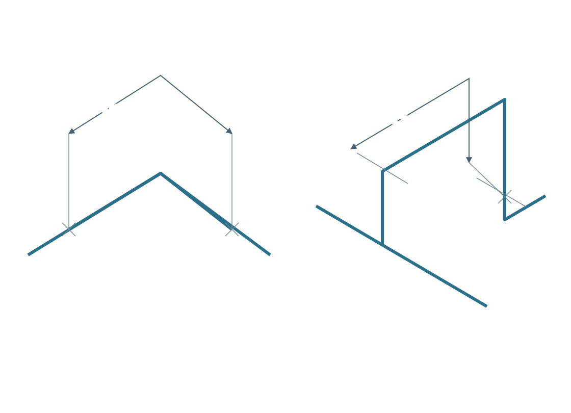
Figure 11.2. Native schematic reconstruction of the two shape definitions. Crosses mark the indicated support stations. The dimension paths retain the selected bend/offset construction. comes from the applicable straight-span table, and or belongs only to the corresponding illustrated shape. No dimensions of a real installation are supplied. Structured geometry, full lookup data and conditions retain the associations.
Table 11.2. Set A maximum straight spans, mm, under the material/wall/temperature conditions above.
| DN |
Vapour, bare |
Vapour, insulated |
Liquid, bare |
Liquid, insulated |
| 25 |
3,850 |
2,300 |
3,450 |
2,250 |
| 40 |
4,750 |
3,000 |
4,100 |
2,800 |
| 50 |
5,350 |
3,600 |
4,550 |
3,300 |
| 80 |
6,550 |
4,600 |
5,450 |
4,200 |
| 100 |
7,500 |
5,550 |
6,100 |
4,900 |
| 150 |
9,150 |
6,800 |
7,100 |
5,800 |
| 200 |
10,500 |
8,050 |
7,950 |
6,700 |
| 250 |
11,800 |
9,050 |
8,700 |
7,400 |
| 300 |
12,900 |
9,800 |
9,150 |
7,800 |
| 350 |
15,150* |
11,850 |
10,850 |
9,300 |
| 400 |
16,250* |
12,850 |
11,200 |
9,750 |
| 450 |
17,250* |
13,750 |
11,500 |
10,150 |
| 500 |
18,200* |
14,450 |
11,750 |
10,400 |
| 600 |
18,950* |
16,050 |
12,150 |
10,950 |
The five starred bare-vapour cells are limited by deflection. All other Set A cells are limited by longitudinal bending stress under this method.
Table 11.3. Set B maximum straight spans, mm, for austenitic stainless Schedule 10S up to 350°C. All cells are limited by longitudinal bending stress under this method.
| DN |
Vapour, bare |
Vapour, insulated |
Liquid, bare |
Liquid, insulated |
| 25 |
3,900 |
2,200 |
3,450 |
2,100 |
| 40 |
4,850 |
2,800 |
4,000 |
2,600 |
| 50 |
5,450 |
3,300 |
4,300 |
3,000 |
| 80 |
6,700 |
4,050 |
4,950 |
3,500 |
| 100 |
7,650 |
4,800 |
5,300 |
4,000 |
| 150 |
9,400 |
5,750 |
5,950 |
4,600 |
| 200 |
10,750 |
6,800 |
6,450 |
5,200 |
| 250 |
12,000 |
7,600 |
6,950 |
5,650 |
| 300 |
13,000 |
8,250 |
7,350 |
6,050 |
| 350 |
13,750 |
8,700 |
7,600 |
6,300 |
| 400 |
14,700 |
9,450 |
7,750 |
6,550 |
| 450 |
15,650 |
10,150 |
7,850 |
6,750 |
| 500 |
16,450 |
11,000 |
8,400 |
7,300 |
| 600 |
18,050 |
12,700 |
9,050 |
8,050 |
Both insulated columns include insulation and sheeting. Their insulation basis varies from 70 mm thickness at DN 25 to 200 mm at DN 600, with density 190 kg/m³. That stated range does not supply an exact thickness at every intermediate size. Actual insulation, sheeting, contents and concentrated component weights must agree with the selected basis or be evaluated separately. The liquid-column heading alone does not establish a universal fluid-density permission.
Free-draining piping with slope below 1.5 mm/m requires an additional span evaluation. Sag can defeat drainage even when the tabulated bending or deflection condition is met.
Material/wall changes can change the applicable set and span. Do not select the heavier-wall set solely for its larger values. Equipment reactions, local bearing, lift-off, test weight, thermal movement, vibration and receiving structure remain separate evaluations; passing the table does not establish drainage margin. Lookup/comparison data and the calculation script preserve illustrative rows and assumptions.
Choose support behavior before choosing a detail
A sliding rest is attractive when the line can carry its weight through a bearing point and remain on that point over the required travel. Its shoe must be long enough to avoid moving off the supporting steel during expansion or contraction. The sliding surface does not make the system frictionless. Resistance to movement changes reactions at anchors, guides and terminals. Its effect must be considered in both the piping and support design.
The analysis convention used here does not credit friction merely to obtain lower pipe loads or stresses. Its allowance for assuming frictionless unrestrained movement is limited to a system supported entirely by rod or spring hangers. Even when that convention applies, consider hanger geometry. Rod rotation can alter the load transmitted to a nearby nozzle.
Where the line moves vertically, a rigid rest may either resist that movement or lose contact. A spring offers a different load path. It carries a selected load while allowing vertical travel. A variable spring changes force through that travel. A constant support is intended to maintain supporting effort over its range. Selecting a spring therefore requires load and movement data, not only a pipe size.
A project may use a 25% installed-to-operating load-variation criterion. Under that criterion, a variable support may be selected at or below the limit. A constant support is specified above it. The reference load and calculation convention for that percentage must be defined in the project selection procedure. The criterion alone does not supply a denominator.
A constant support can also be appropriate for large vertical movement or when a variable spring becomes impractical. It can also be appropriate when changing spring reaction would transfer excessive load to a critical terminal. Check the actual load-sensitive equipment as well as the selected percentage criterion.
Route the attachment choice through the material and thermal interfaces
After selecting the required support behavior, choose the way the reaction reaches the pipe. Figure 11.3 shows a conditional metallic-piping selection route. It starts with insulation. Exposed pipe bearing on steel, a shoe on a hot line and a clamp outside cold insulation have different structural and thermal interfaces.
A cold-insulated line leaves the ordinary shoe-selection route for its qualified insulation-system procedure. The support must carry the required loads without opening the moisture barrier. Load-bearing insulation, friction and erection/test sequence must be established together. the cold-support account below develops that interface.

Figure 11.3. Conditional selection questions for the stated metallic-support procedure. “Yes” and “no” preserve the branches and shared joins, including the separate cold-insulation route and special clamped/welded exits. CS means carbon steel and SS means stainless steel. The direct-bearing endpoint still needs the design conditions discussed here. The structured question map retains every node and branch. The endpoints select an attachment route, not an allowable reaction.
For an uninsulated pipe, the illustrated route asks successive questions:
- Is fluid temperature below ambient?
- Does the pipe need a slope?
- Is size above DN 600?
- Is wall below Schedule 20 for carbon steel or Schedule 10S for stainless steel?
Any “yes” moves the line into shoe selection. Only “no” to all four reaches direct bearing on the supporting beam. The design conditions also exclude direct bearing where sufficiently low temperature can embrittle the receiving member. They exclude it where pipe movement and water collection can cause unacceptable corrosion.
A pipe shoe protects the pipe interface. It does not cure corrosion of the supporting steel. These additional conditions must travel with the question map. A slope correction remains small under this procedure, which limits shoe height measured below the pipe to 400 mm.
Within shoe selection, a noncorrosive carbon-steel line follows the clamped route. A corrosive environment or another metallic material first reaches the lining/coating question. A lined or corrosion-resistant-coated pipe follows the clamped route. Otherwise, the need for post-weld heat treatment sends it to the clamped route. Absence of that need reaches the welded route. On either route, high forces/moments or temperature above 400°C requires a specially designed support of that attachment type.
The questions contain no numerical definition of “high” load. Compare the evaluated load with the selected hardware’s applicable geometry, material and temperature capacity. Do not invent a threshold from the diagram.
The accompanying design conditions qualify those outcomes. Welded supports are excluded on:
- Glass-, rubber- or plastics-lined piping
- Piping requiring PWHT
- Corrosion-resistant coatings such as galvanizing
- Specified expensive materials such as titanium, Hastelloy and Monel
A branch reaching “welded” cannot override those exclusions. If a supporting attachment is required on PWHT piping, its separate fabrication route identifies it on the isometric. The attachment is made in the workshop before heat treatment. That shop sequence does not permit an unrestricted field weld. Supporting attachments welded directly to pipe use the same material type and carry their identification into the drawing.
Clamps retain their own conditions:
- Protect against retained water.
- Where needed, provide appropriate insulating separation between a carbon-steel clamp and another metallic pipe.
- Evaluate loss of grip as clamp and pipe change temperature differently.
Where the procedure calls for weld-on shear lugs to prevent slip, restore the affected paint after welding. That local weld is itself subject to the pipe’s material, treatment and examination requirements. A clamp endpoint therefore does not remove all welding or inspection decisions.
For hot insulated piping above 400°C, the procedure calls for alternatives. These are incombustible blocks with adequate thermal and load-bearing properties between shoe/cradle and structure, or a qualified clamp around load-bearing insulation. For insulated piping generally, maintain at least 50 mm clearance to the supporting structure.
The cold-insulation route includes movement in that clearance and checks friction against the insulation's capacity. Glass-lined and plastic systems retain their supplier's installation instructions. The metallic map cannot assign their bearing or attachment capacities. Galvanized supports are excluded by this procedure for austenitic and duplex stainless steel, nickel alloys and 9% nickel steel.
The selected attachment, freedoms, local wall, receiving steel and foundation must carry the actual reactions. Preserve the material/fabrication route, insulation/barrier treatment, weld/examination requirements and installed freedoms in the detail.
Size and maintain the sliding interface
Friction belongs to the contact that actually carries the line in the state being examined. In a simple dry-contact model, the limiting static tangential resistance is . In this equation, is the compressive normal reaction. is the dimensionless static coefficient for the adopted surface pair. If is in kN, the limiting force is in kN.
Before slip, friction responds to the demanded tangential force up to that limit. It is not always equal to .
The relation supplies neither a kinetic coefficient nor a complete thermal-displacement solution. If the support lifts clear, the compressive contact and its friction path disappear. Use the reaction at that support rather than dividing the total line weight equally among supports without justification.
One specifically adopted support-design basis uses the following static coefficients. They are design inputs of that basis, rather than measured constants for every installed surface or permissions to substitute material pairs.
Table 11.4. Static-friction inputs under one adopted sliding-support basis.
| Contact pair |
Static coefficient, |
| PTFE on PTFE |
0.10 |
| PTFE on stainless steel |
0.10 |
| Steel on steel |
0.40 |
| Steel on concrete |
0.45 |
The displacement solution must reconcile friction with restraint stiffness, thermal growth, load redistribution and contact. An adopted prohibition on beneficial friction credit remains controlling even if adding friction lowers one numerical reaction.
A low coefficient is useful only while the interface preserves the conditions on which it depends. Corrosion, sand and dirt can increase resistance, while damaged bonding can change contact or let a pad move independently of its backing. One support procedure therefore specifies a stainless landing surface. It minimizes low-friction elements because even that surface can foul. Where low friction is necessary and the hanger’s service restrictions permit it, the procedure considers a hanger. The alternative retains the rod-swing and fire-exposure questions already discussed.
Other adopted details deliberately use PTFE on a stainless mating pad. They protect the pad from weld spatter and require cleaning loose particles before loading the line. A graphite pad's bonding method needs demonstrated performance in similar applications under its selection procedure. These are construction and maintenance conditions of the load path, not finishes that can be selected after the analysis is complete.
The bearing temperature also has a local reference. The PTFE shoe and adjustable-base details considered here limit metal temperature at the PTFE to 400°F (about 204.4°C). This is a restriction of those particular details. A process-fluid temperature, the opening chapter's metallic support range, or a different PTFE product rating cannot establish that this interface meets it.
Establish the temperature at the bearing and the qualified load and attachment arrangement before selecting the detail. Conversely, a hot line does not establish the pad temperature without evaluating the intervening shoe and heat path.
Travel needs a swept bearing area. Under the adopted PTFE-pad procedure, the upper pad must overlap the lower by at least 1/2 in in both cold and hot positions. Alternatively, a cover must prevent dirt reaching the pads.
Distinguish that protective edge coverage from the separate need for sufficient load-bearing contact and shoe-to-beam support. A cover addresses contamination. It does not restore contact after a shoe runs off the beam. Loss of support followed by a temperature reversal can catch the shoe against the steel and damage the support or pipe.
For a centered rectangular pad, Let and be upper and lower pad lengths in the travel direction. Let be the upper pad’s displacement relative to the centered position, and the required edge coverage. Full lower-pad coverage with that margin requires:
All quantities are lengths in the same units. Check both directions, actual cold/hot offsets and tolerances separately. This centered model does not reinterpret a catalog movement label or establish pad pressure, bond strength, support capacity or allowable temperature.
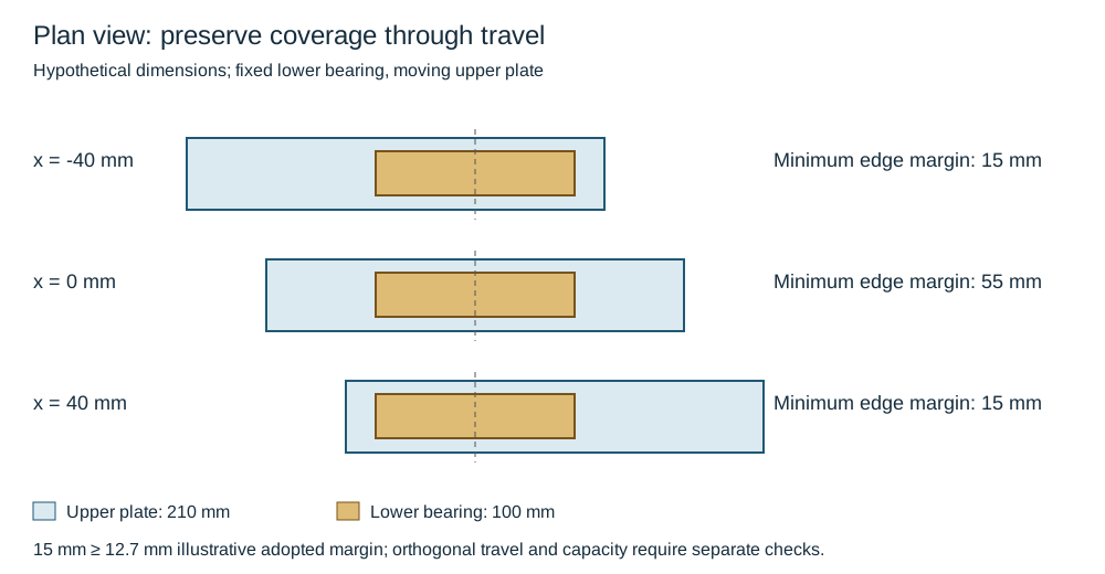
Figure 11.4. Plan views of the authored rectangular example at three relative positions. The fixed lower bearing stays covered by the moving upper plate. The limiting longitudinal edge margin is 15 mm. Dimensions are hypothetical and the other direction is not assessed. The structured companion preserves the geometry, assumptions and checks.
Choose a pad arrangement whose surfaces can be cleaned and whose coverage, bonding and travel can be observed. At commissioning, verify the installed relative position against the defined reference state. In operation or after adjacent work, unexpected restraint, debris, displaced pads or a shoe approaching an edge calls for investigation. Investigate the contact and movement basis before adjustment. Replacing a steel contact with a low-friction pad is a mechanical modification. It can change reactions and motion elsewhere even when the nominal support location stays the same.
Relate spring load change to travel
A variable support may operate over a range in which its rate can be treated as linear. In that range, the magnitude of load change is . is supporting force, is spring rate in force per unit travel and is vertical travel. Direction determines whether travel loads or unloads the spring. The rate and usable travel come from the selected device. They cannot be inferred from pipe diameter alone.
If the selected procedure defines variation relative to operating load, use:
That denominator is conditional, not supplied by the bare 25% criterion. Use the prescribed convention. Satisfying its percentage still leaves capacity, travel, terminal reactions and intermediate/empty states to be checked.
For an initially vertical fixed-length rod of length , the simple pivot model gives horizontal shift . An adopted 4° swing limit therefore requires for that geometry. Vertical movement and actual attachment geometry can change both travel and force.
A constant support is selected for its specified supporting effort and travel, not by assigning a smaller rate to an arbitrary variable spring. Calibration, load indication, available movement and the cold/hot reference settings are necessary parts of the actual device. Keep the selection data connected to the installed hardware and to the test and empty-state instructions.
Preserve the directions assigned to hangers and restraints
A suspended rod hanger can solve a lack of support space beneath the line, but horizontal movement swings the rod. Where the project adopts a 4-degree swing limit, size and position the hanger to respect it. Account for the rotation and its nozzle-load consequence in the analysis. A suspension arrangement that appears free in plan can therefore become unfavorable near a sensitive terminal. Under an adopted procedure that excludes hangers for two-phase flow or excessive vibration, that exclusion remains part of the support choice.
When a suspended rod cannot survive pool-fire exposure, a catch beam or other evaluated means of preserving support can be required. Coating the rod with fire protection is not automatically an adequate solution. Space, structural attachment elevation and the required travel belong in the choice between a hanger and a support from below.
Guides, stops and anchors control movement, stabilize geometry and resist static, transient or dynamic forces. Each restraint added to suppress an unwanted movement also changes the freedom available for thermal expansion. Natural flexibility from routing and fittings should be considered early, while rerouting remains practical. An expansion joint adds a specialized movement mechanism but also introduces anchor and guide obligations. An unrestrained joint cannot be accepted as an automatic cure for a stiff line. Pressure thrust and hydrostatic-test restraint must be considered, and the anchor-guide system must follow the applicable code and the established joint design basis.
This interplay is especially clear in vibrating piping. A restraint can increase stiffness and reduce vibration while worsening thermal stress. Thermal analysis can identify a point whose displacement in a particular direction is zero: a null point. Restraint in that direction at the null point can oppose vibration without obstructing the predicted thermal movement.
If the useful restraint cannot be located there, thermal and natural-frequency calculations must be repeated for the proposed position. A null point is tied to the analyzed condition and direction. It is not a universal permission to anchor the pipe in every direction or every state.
Reciprocating machinery requires a distinct dynamic treatment. Support locations and spans influence mechanical response to pulsating flow. A successful arrangement copied from another machine is not sufficient evidence for a new one. A metallic-support specification may require:
- Transverse restraint of pulsation-prone lines from reciprocating compressors or pumps, regardless of an acoustic study
- Evaluation of clamp coupling moments and dynamic loads
- Consideration of independent supporting structures where feasible
If that specification excludes sway braces for these lines, a generic vibration-control detail cannot override the exclusion. This treatment should not be generalized to every vibrating line. Acoustically induced vibration calls for assessment of vibration and fatigue. It also calls for consideration of suitable attachment forms, including bands, bolted supports or stiffening rings.
Match a restraint's response to the motion being controlled
A direction label alone does not describe a dynamic device. A sway strut restrains a selected direction while allowing movement in another. A sway brace uses its adjustable spring or friction behavior to oppose sway, vibration or shock under its specification. A snubber offers a different response. It permits slow movement while resisting sudden motion. This can preserve gradual thermal travel while transmitting an impulse reaction from an earthquake, flow transient or wind gust.
Model the selected device's response and attachment direction rather than replacing it indiscriminately with an always-rigid anchor. Its usefulness depends on the actual transient and thermal sequence, load capacity and travel.
One specifically adopted mechanical-device specification reduces allowable material stresses by 50% for vibration duty. It requires buckling resistance and self-aligning spherical end bushings allowing at least 10° rotation in any plane. It provides a securely locked adjustment of ±40 mm. Its snubber requirement includes operation from 3 to 33 Hz. Snubbers and sway braces have readable travel scales. These values describe that specification, not universal capacities or tuning rules.
End articulation accommodates changing geometry. It does not permit the assembly to run out of stroke or the attachments to bypass their load checks. Preserve the separate prohibition on sway braces for reciprocating-machine lines where that support criterion is adopted.
Specify allowed movement, resisted transient, travel/force response and both end-attachment load paths. Preserve articulation, adjustment and access to indications/connections in installation. A travel scale does not prove dynamic response; inspection and functional testing follow the device’s qualified procedure.
Follow the reaction beyond the pipe
A pipe-support detail is only one part of the load path. The shoe or clamp transfers load into a bracket or beam, then into structural framing, concrete or a foundation. Supporting several restrained lines on the same structure requires consideration of the most severe combination of their loads. A satisfactory individual support does not prove that the shared structure is adequate.
Likewise, paving or grating should not be treated as a structural foundation merely because it lies under the pipe. Establish its capacity and installation criteria. When paving capacity is exceeded, provide an independent foundation. Handrails, ladders and other structures not intended to carry these loads are unsuitable attachment points.
At equipment, include both force and moment. The nearby dead-weight support used for a vertical vessel line reduces the load imposed on its nozzle, while lower guides limit sway and associated moments. The vessel attachment must still carry the support reaction, including applicable temporary installation and hydrotest states. Heater piping illustrates coordination at a moving terminal. The supplier of a furnished manifold needs proposed piping loads and any movement associated with rod or spring support. The supporting steel and piping cannot be designed independently and reconciled only at erection.
Minimize weight and weight moment at load-sensitive equipment, then evaluate complete nozzle loading.
When the project criterion selects the lesser of manufacturer limits and applicable reference limits, evaluate both unless an authorized project decision establishes otherwise. API 618 and API 661 provide equipment-specific reference routes for reciprocating compressors and air-cooled exchangers respectively. The reference applicable to the actual equipment and contractual edition must be established. A generic terminal allowable is not justified by the fact that a stress calculation passes for the pipe.
Attachment design also interacts with the pipe wall. Welded attachments near elbows can reduce flexibility, and large thin-wall lines need evaluation for local crushing at concentrated support loads. For pipe greater than NPS 24, the selection criteria discussed here require determined allowable spans and bearing reinforcement or wear pads. These are local load-transfer questions as well as global span questions. A large line that passes an overall bending check can still require a different bearing arrangement.
Insulation adds both weight and an interface that must survive movement. Shoes on insulated lines provide a sliding surface without making the insulation carry damaging movement. Cold-insulated supports must avoid cold bridges, vapor-barrier penetrations, crushing, condensation and ice. Thermal and acoustic insulation thicknesses affect the support geometry. Do not resolve a support interference by cutting away insulation without reconsidering those functions.
Material and fabrication constraints can change the preferred attachment. Clamp-on shoes are an alternative when welding is forbidden or impractical, including internally lined or galvanized piping and piping requiring post-weld heat treatment. A fabrication procedure that restricts field attachment welding on these materials can require workshop attachment welding before heat treatment. Thus a last-minute support weld is not a neutral field correction. It can affect heat treatment, lining, coating and flexibility, and may require a different attachment or revised spool fabrication. Specify attachment materials using the applicable pipe material, service temperature and project rule.
Some temperature and material combinations permit carbon-steel attachments. Others require the pipe material or a compatible composition. “Match the pipe” alone does not resolve that selection.
A process line used as a carrier acquires another load and movement role
An intermediate cross member can carry small lines between rack bents by hanging from larger process lines. In Figure 11.5A, the smaller-line reactions enter the cross steel, then its attachment or shoe, the carrier process lines and finally those lines' own supports. Reducing the smaller lines' unsupported length therefore increases demand in pressure-containing members. Evaluate the carrier’s bending, local attachment, contact and stability together with the cross member. Adequate smaller-line spacing alone does not establish that coupled load path.
The selected arrangement uses a U-bolt at an uninsulated carrier and a shoe welded to the cross steel at an insulated carrier. These labels do not establish a complete freedom set. Identify which interfaces grip, bear or slip and whether the two carriers can move differently. A cross member joining lines with different growth can restrain one or both, redistribute reactions and load the pressure-wall attachment.
An insulated carrier’s growth at the proposed station must be evaluated. Selecting another carrier or independent structural steel can avoid an unsuitable restraint. Any project prohibition on supporting one pipe from another remains controlling.
Consider the empty, filled, operating and test states of each participating line, including cases where one carrier is hot and the other is cold. Removal of a carrier or its shoe can interrupt support of lines that remain in service. Before dismantling such an assembly, provide a governed temporary load path. Retain inspection access to the carrier wall and attachment. Treat the configuration as an explicitly evaluated inter-pipe support arrangement, rather than a shortcut around structural steel design.
A vessel-mounted guide has a moving reference and a sliding interface
Figure 11.5B shows a different pressure-boundary carrier. Vessel-mounted bars or plates lead to a pipe clamp around a vertical line. The selected guide detail has a sliding fit with diametral clearance, rather than a weight-support grip. Its purpose is to control lateral response while allowing the line's intended axial movement relative to the vessel. Define the actual clearance, friction, alignment and travel. A clamp symbol does not prove axial freedom after tightening, corrosion, insulation or field adjustment.
The vessel fabricator supplies the required shell-mounted attachment parts under this detail. Thin-wall shell distortion requires investigation, and guides should not be placed too close to a point where horizontal expansion would distort the guide or vessel. Vessel growth is a boundary movement, not stationary ground. To establish travel and loads:
- Combine the shell’s movement with the line’s growth to obtain relative travel.
- Then carry lateral guide reactions into the attachment and shell assessment.
A separate riser support carries weight. Neither guide spacing nor a sliding fit supplies that vertical load capacity.
The selected guide chart's spacing assumptions include wind on projected insulated pipe and a bounded deflection criterion. Its numeric spacing is not exported here as a universal interval. The native panel retains the contact and attachment topology without reconstructing an unresolved drawing-callout suffix. Actual bar/plate material, welds, clamp dimensions, clearance and guide spacing remain on their qualified detail basis. Vessel-carried equipment and work structures pose the same load-owner question at a larger scale, with different loads and acceptance requirements.

Figure 11.5. Separate conceptual arrangements: A, small-line reactions transferred through cross steel to two carrier process lines; B, a vessel attachment leading to a sliding guide around a vertical line. Arrows identify the evaluated load or movement direction, not allowable forces. Structured interface data keep the arrangements and their freedoms separate.
Establish the common structure's abnormal-load combination
An anchor bay carries the thrust through its frame and bracing into foundations. A support beam intended to carry ordinary pipe weight may have a different structural function. One long-run support basis normally assigns thermal thrust to anchor bays rather than to every elevated support. Accordingly, identify which members carry the restraining reactions, including their tensile and compressive paths. An anchor symbol does not demonstrate that the frame or foundation carries those reactions.
That same basis defines abnormal thermal conditions to include:
- Loss of cooling
- Stopped process flow with line heating still active
- Anticipated start-up, shutdown, steam-out and upset temperature changes
For the common anchor structure it adopts the following grouping. It also requires each piping anchor to be designed for the governing normal or abnormal force.
Table 11.5. Conditional abnormal-line grouping for one anchor-structure design basis.
| Lines at the structure capable of abnormal conditions |
Fraction assigned abnormal conditions in this grouping |
| 1 |
100% |
| 2–4 |
50% |
| More than 4 |
25% |
Round the resulting number up to the next whole line. The selection note generally chooses the largest lines where their thrusts act in the same direction.
The direction condition matters. Diameter alone does not identify the governing force combination when temperatures, restraint geometry or thrust directions differ.
Keep the grouping tied to its governing support basis and operating scenarios. It is not a probability model proving that a common loss of cooling can affect only a quarter of the lines. It does not replace applicable coincident-load requirements of another project basis. Establish credible shared process events and the directional force/moment combinations for the actual structure.
Do not convert the percentage into a reduction of every anchor reaction or blend it with an unrelated load-combination rule. Carry the chosen combination, its affected lines and reaction references into the structural and foundation assessment. A later added line can then reopen the correct calculation.
Long horizontal runs also need lateral stability. Static friction opposing thermal expansion can develop axial compression. The adopted long-run procedure requires that thrust not exceed the critical buckling load. It adds lateral guides where needed. The friction coefficients and anchor arrangement therefore affect a stability question as well as nozzle force. Guide spacing and capacity must follow the actual pipe/structure model.
No Euler-length or buckling capacity is inferred from the count table. Under this basis, friction is not credited to reduce thermal movement or flexibility stress.
Choose how the reaction enters the pipe and structure
A shoe provides a bearing surface and height for the selected movement and insulation arrangement. Its length must retain contact over both directions of travel. Its attachment must carry the resulting reactions. Low-friction pads reduce resistance under their qualified load and temperature conditions. Dirt, loss of overlap or an unsuitable bond can defeat the intended sliding interface. Check the hot and cold bearing positions instead of inspecting overlap in only the installed position.
A clamp can be adjusted during erection and can avoid a prohibited field weld. Its grip, local bearing and slip resistance must serve the intended function. Retained water between clamp and pipe can increase corrosion, and dissimilar metals can require a compatible separation layer. Thermal differences between clamp and pipe can loosen the grip. A procedure may require compatible shear lugs to prevent slip in that service. Those lugs restore a load-transfer feature while introducing welding, coating and inspection requirements.
A clamp used as a guide or anchor cannot be assumed adequate because it carries weight successfully.
For an adopted procedure prohibiting galvanized supports on austenitic or duplex stainless steel and nickel alloys, that exclusion remains controlling. Another metallic clamp table permits galvanized or coated carbon steel for specified material and temperature bands. Its selection cannot override the exclusion in the first procedure.
A welded shoe, lug or trunnion transfers load through its weld and a local region of the pressure boundary. Trunnions and dummy members can reach a nearby beam where a direct rest cannot. Their own bending, attachment welds, parent-pipe wall and stability require checks, with the actual load direction and temperature.
A dead-ended process extension is not an equivalent structural dummy. It can retain stagnant fluid and create a different corrosion exposure. A tubular structural dummy can require a low-point drain hole under its adopted detail. That hole is not permission to drill the operating pressure boundary.
Riser clamps, lugs or collars carry vertical weight while guides control lateral movement. Tower-mounted piping needs the vessel's thermal movement and the line's growth considered together. A high support and suitably spaced guides can reduce differential movement or sway, but the vessel clips and local shell must receive acceptable loads. Use the fabricator's provided attachment route where the adopted procedure forbids field welding to the vessel. The horizontal transport/erection configuration of a vessel can reverse the load direction on its piping attachments.
Large-diameter thin-wall pipe needs special attention at the bearing point. Increasing span capacity through overall pipe geometry does not prevent local crushing or distortion. Under the metallic criterion for pipe greater than NPS 24:
- Determine allowable spans for the actual diameter and wall.
- Provide saddle reinforcement or wear pads at bearing.
The stated pad material and minimum 100 mm bearing length belong to that criterion. A shoe may be an alternative where feasible. A specified minimum bearing length does not replace other required pad, weld or attachment dimensions. These provisions do not establish capacity for every larger line. They identify local transfer and abrasion questions that a straight-beam span check misses.
Make containment and restraint visible in the construction detail
A support drawing has to show two different boundaries: where the process fluid is contained and where the support reaction is transmitted. In the external tubular base of Figure 11.6A, the process wall continues across the attachment. The hollow member below it carries structural load through the attachment weld and base into the foundation. Its cavity does not communicate with the process bore. A weep opening near the member's low point drains that external cavity. Moving that opening into the parent pipe, or burning through the parent wall while making the attachment, changes containment rather than improving support drainage.
A horizontal dummy reaching a beam has the same separation at its root. Its end closure, bearing and drainage arrangement differ from the vertical base. A process dead leg would instead remain connected to the fluid and introduce the stagnant-fluid and solids-retention exposure.
The illustrated separation does not make the attachment structurally harmless. A reaction entering the exterior still bends and loads the local process wall. Establish the parent wall, attachment material, weld procedure, temperature and required examination or heat treatment alongside the dummy's length, orientation and end connection. Where fabrication requires attachments before coating, lining or stress relief, carry that sequence into the shop and field detail.
The vertical base example separates the pipe-fabricator attachment from the support-fabricator extension and base. The field cut and bevel must preserve the specified joint and intact process wall. The base plate, its fastening and the receiving concrete complete a different part of the same load path. None of these checks is replaced by providing the drain opening.

Figure 11.6. Two distinct construction examples, drawn conceptually without catalog dimensions or capacities. A: an external hollow base member attaches to an intact process wall. Its low-point opening serves only the external cavity. B: shoe-mounted stops straddle a supporting beam with gaps. Their beam-facing surfaces remain unwelded so that axial contact can develop while sliding along the beam remains available. The two panels are separate details, not a combined support assembly.
The directional-stop example in Figure 11.6B shows how a restraint is made by contact rather than by the word “anchor.” The shoe bears on the beam. Two plates attached to the shoe lie outside opposite beam edges, with clearance between each plate and the adjacent edge. Axial displacement first consumes one gap. Contact then transfers thrust from the shoe through that plate into the beam. Reversal releases that face and can take up the gap at the opposite plate.
This is a pair of unilateral contacts, rather than an always-active fixed point. The stops do not provide the transverse guide function. Travel along the beam remains geometrically available, subject to bearing overlap, friction and any other installed restraint.
The attachment welds must connect each stop to the intended moving shoe while leaving the indicated beam-facing sides unwelded. A field weld bridging a gap or joining the shoe to the beam would change the movement path and the resulting thermal reactions. The selected example belongs to an insulated carbon-steel shoe arrangement with its own shoe-length and fabrication requirements. It is not an interchangeable detail for a clamped alloy shoe, a hold-down or a lateral guide.
In particular, a stop beneath the shoe does not establish uplift restraint. Pipe-axis rotation, other rotations and the pipe-to-shoe attachment still need their own physical load paths and model treatment. The clamped-shoe torsion release explained below cannot be transferred to a welded arrangement solely because both use stops.
For analysis and installation, record:
- The pipe-axis direction
- Each contact face and its gap
- The transverse travel and vertical bearing condition
- Any separate hold-down or guide
Relate those features to the cold, operating and test positions. Check that the shoe continues to overlap the beam throughout permitted movement and that the stops remain able to engage their intended faces. A gap that closes in operation changes the load path. Loss of bearing or lift-off changes it again.
Use the actual clearances, stiffness, friction and connection geometry when evaluating reactions. The drawing here supplies the contact topology, not a gap value, weld size or allowable reaction. With that topology explicit, the assessment below can carry the engaged reaction into the pipe attachment, shoe, beam and foundation. It need not assume six restraints from a single symbol.
Construction-interface data
Keep examination access in the attachment decision
A base under an elbow can shorten the weight-load path at the bottom of a riser. It can occupy the region an inspection crew needs to reach. Figure 11.7 compares an attachment on the straight run with one on the elbow. The off-elbow arrangement leaves the elbow's exterior more accessible. The elbow-mounted member covers a local sector and changes where a probe, scanner, source or other examination equipment can be placed.
The actual method, required surface access and inspection volume must be established. A clear-looking sketch is not evidence that every required sector can be examined.

Figure 11.7. Conceptual attachment locations. A selected inspection-oriented procedure prefers the off-elbow alternative because mounting under the elbow limits available NDT methods. The shaded sector in the elbow-mounted example indicates attachment occupation, not a certified examination-coverage boundary. Structured alternatives retain the access and policy distinctions.
Keep that preference separate from a construction procedure that permits a particular elbow or tee base. The external-base example in Figure 11.6 is a bounded detail for NPS 6 and 8. It has an intact process wall, an external weep opening, specified fabrication joints and PWHT as required for the process pipe. Its permission does not cancel an inspection-driven preference to move the attachment off the elbow. Conversely, an off-elbow preference does not prove that every permitted elbow base is prohibited. Select the governing procedure and resolve the examination access for the actual assembly before releasing the detail.
Another selected fabrication procedure requires at least 50 mm between a stanchion/dummy attachment weld and the fitting weld when attaching to elbows or tees. That spacing separates weld regions under its own procedure. It does not certify scanner clearance, every NDT method or local pipe-wall capacity. The external member and root weld also need their structural and material assessment. Inspectability, load transfer and fabrication access are distinct requirements that must all be met.
Changing to a straight-run attachment can change span lengths, lever arms and local reactions. Recheck those consequences and the room needed for insulation, drainage and maintenance, rather than moving the support solely to clear one inspection tool. Retain the examination method and accessible sector in the construction/inspection record. Added insulation, bracing or a replacement attachment must not quietly remove the planned access.
An anchor detail needs the right freedoms and load reference
A full anchor model restrains three translations and three rotations. Achieving those six functions requires an actual load path and adequate stiffness. It is more demanding than restraining translation alone. In the clamped shoe family considered here, the clamp does not provide the pipe-axis torsional restraint assumed by a full six-freedom anchor.
Release rotation about the pipe centerline in the piping model, so that the torsional reaction at that pipe reference is zero. The remaining forces and bending moments still act. Welding the shoe to the pipe can provide the additional torsional load path under the applicable detail. Its pipe, weld and structure must be assessed.
Do not erase a real torsional demand from a fully restrained model merely by editing its reaction report. Releasing the freedom changes the system's response and redistributes loading. The piping analysis must represent that freedom. Nor does zero pipe-axis torque at the clamp mean that the shoe base sees no moment about a parallel axis. A lateral force acting above the base produces its own moment there.
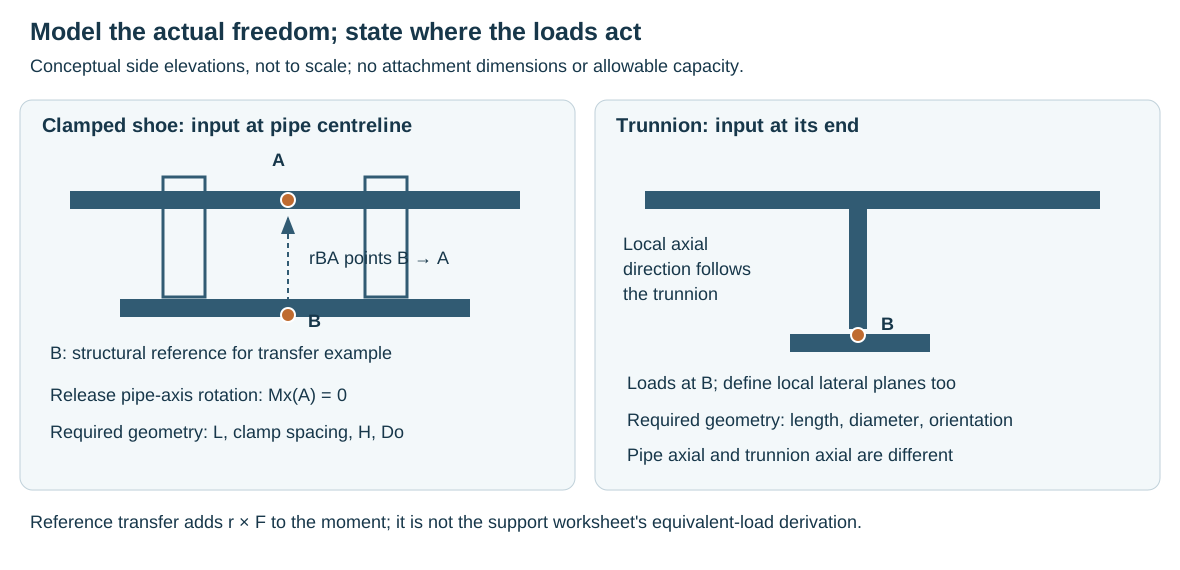
Figure 11.8. Conceptual side elevations. The shoe assessment starts with loads at pipe centerline A. A trunnion assessment can start at its end B with axes defined along the trunnion. The reference offset is actual geometry, not a formula inferred from the symbol H. Clamped-shoe pipe-axis rotation is released. All other stated restraints still need their physical load paths.
For a shoe, establish total length, clamp spacing or spacing between welded attachment areas, shoe height, nominal size and actual outside diameter. The spacing changes how a moment is distributed into clamp or weld regions. Height and diameter influence the offset between a pipe-centerline reaction and the structural attachment. Nominal diameter is an index to the correct product dimensions, not the measured outside diameter. Clamped and welded shoes can have different attachment spacing even at the same nominal size.
For a trunnion or structural dummy, establish its length, diameter, orientation, attachment and end connection, and identify where the input loads are defined. A load axial to a vertical trunnion is not axial to its horizontal parent pipe. In-plane and out-of-plane lateral loads also have different references. Select the relevant allowable direction and geometry range before comparing numbers. A long lateral lever can govern local parent-wall bending even where direct axial loading has greater capacity.
A simple reference transfer illustrates the distinction. With forces and moments expressed in the same Cartesian axes, moving a force/moment system from A to B gives:
In this equation, points from B to A. Force is unchanged by translating the reference. Moment includes the additional lever-arm effect. If the assessment uses different local axes, rotate both force and moment components as well. This statics transfer does not supply the separate equivalent-load transformation of a support worksheet.
The support assessment then combines the supplied forces, moments and geometry into equivalent component loads for its applicable allowable comparison. Comparing only the original three forces can miss the equivalent demand created by bending moments. The calculation needs the correct load reference, axes, geometry, attachment arrangement and allowable table. Its transformations are part of that method, not an interchangeable sum of absolute force and moment values, which have different units.
Compare each transformed equivalent component with its applicable allowable; the resulting load fraction is dimensionless. The component check alone does not qualify the complete pipe, weld, anchor or foundation.
A moment entered in kN·m must first pass through the method's geometry-dependent conversion. It cannot be compared directly to a force allowable in kN.
The detailed worksheet derivation is not supplied here. The retained worked trunnion example has inconsistent axial/lateral allowable assignments and a reported maximum fraction that does not follow the printed table assignment. A worked shoe example labels a load fraction with a force unit. Those discrepancies prevent reproducing their reported acceptance as a verified result. Keep the component mapping and derivation unresolved rather than inventing a hidden equation or inferring that every trunnion is stronger than every shoe.
Table 11.6. Support-detail functions and interfaces.
| Detail family |
Function to establish |
Consequential interface |
| Sliding shoe/rest |
Carry weight while retaining intended travel and contact |
Bearing length, friction, insulation height, wear and supporting beam |
| Clamp attachment |
Carry specified forces without harmful slip or local damage |
Grip, thermal loosening, corrosion, separation material and adjustment limits |
| Welded lug/shoe/trunnion |
Transfer reactions through a qualified local attachment |
Parent wall, weld/material, temperature, heat treatment and examination |
| Riser support with guides |
Carry vertical weight and limit lateral response |
Vessel/structure movement, local shell/clips and separate guide freedoms |
| Spring/hanger |
Carry selected load through defined travel |
Rate or constant effort, swing, calibration, settings, locks and empty state |
| Anchor/stop/guide |
Restrain specified directions and loads |
Pipe flexibility, dynamic reaction, common structure and actual gaps |
Equipment movement and sensitivity are developed in rotating equipment and vessels, heaters and storage. The support choice must deliver the evaluated load path at those terminals.
Fireproofed steel also needs a structural attachment rather than a load carried by the fireproofing layer. Remove and restore the protection under the applicable procedure when attaching to the underlying member. Identification, dimensional detail, allowable load, material and surface protection should travel together into construction. A correctly fabricated bracket installed on an unsuitable beam is not a completed load path.
Adapt the support to insulation and the material system
The opening metallic selection scope does not assign its spans, attachment rules or spring thresholds to polymer, RTR, glass-lined or cryogenic systems. The general questions of weight path, movement, contact and restoration remain useful, but local bearing and joining behavior need the qualified material-system basis. Material selection and Joints explain why those constructions differ.
For aboveground RTR, horizontal spacing is tied to the manufacturer's type, size and wall, operating temperature and liquid relative density. Add fitting and insulation weight rather than treating bare straight-pipe spacing as a finished arrangement. A supported aboveground procedure avoids point load by adequate bearing length. It provides 180° circumferential bearing with suitable elastomeric liners and protects against abrasion and excessive bending. Its vertical bonded collar can contact 360° of the pipe, with guides that restrain lateral response while allowing axial movement. Those are conditions of that RTR system procedure, which excludes underground, mechanical-joint and fire-water scope.
Thermoplastic systems can have lower and temperature/duration-dependent stiffness, substantial thermal movement and vulnerability to sharp contact or abrasion. HDPE can be flexible enough to require a different spacing and handling arrangement from rigid steel. PVC/CPVC and other families have their own limits. Heavy metallic valves should have a load path that does not make the nonmetallic pipe carry an unqualified concentrated weight. Joining and cure conditions also matter during lifting or erection. A support scheme must not impose loads on a joint before its prescribed ready condition.
Lined and glass-lined steel retain a metallic structural boundary but impose constraints on heating, welding and contact that ordinary bare-pipe details do not address. Clamp-on or supplier-qualified support arrangements can avoid damage to the liner. The clamp's own grip, corrosion and local load still need evaluation. Avoiding a weld is one part of the choice, not its completion.
For insulated metallic piping, distinguish the bearing load path from the thermal and vapor-barrier functions. Load-bearing insulation must have the specified capability, and sliding or restraint forces must enter the intended hardware without crushing the insulation or tearing the barrier. Cold bridges and protrusions can cause condensation or ice even where pipe stress is satisfactory. Insulation and thermal protection carries the material and barrier detail.
One cold-insulated metallic trunnion procedure specifies an insulated length . In this equation, is line-insulation thickness and is trunnion-insulation thickness. At least 150 mm of uninsulated trunnion follows.
If that required length cannot be provided, the procedure calls for complete cold insulation of the trunnion or a cold-insulated support. This conditional detail method does not establish a cryogenic support or thermal design.
At small-bore vents, drains and instrument roots, support must preserve connection integrity and intended communication. A brace tied to stationary steel can oppose the parent line's growth. A support following the line can have different response. Added valves or longer insulation extensions change mass and lever arms. Small-bore connections develops the attachment and fatigue evaluation.
For relief and slug-flow piping, supports at direction changes must carry evaluated reaction loads while retaining appropriate movement. A static weight-only detail is insufficient.
A cold-insulated support can also govern erection sequence. In one adopted outer-clamped insulation-system procedure, field insulation at joints is installed after pressure testing, while the supports must already carry the line during erection and testing. Consequently, those field-insulation locations are kept away from the support positions. Leaving the support to be completed after the test would remove a required test-state load path.
The same procedure requires at least 50 mm clearance between insulation and supporting structure while accounting for movement. It checks friction load against the insulation’s load-bearing capacity. If an outer clamp cannot transmit the evaluated anchor or stop reactions, the procedure calls for a specially designed arrangement. That arrangement may use matching-material welded attachments and a qualified insulating load-transfer block.
This alternative changes both structural and thermal interfaces. It is not permission to crush ordinary insulation or omit the vapor barrier. These are conditions of that cold-insulated support procedure, with material-system and cryogenic suitability established separately.
Establish the empty-line condition before releasing a spring
A spring selected for a filled line can exert an unfavorable force when the line is empty. Where the empty-line assessment identifies that risk, the installation procedure can require locking until actual service fluid is present, with a specific warning against empty conditions. Define the filled condition permitting release and how release is checked. Removing every lock immediately after testing can defeat that requirement.
During hydrotesting, use the actual liquid weight, pressure-thrust boundaries and any spring-blocked configuration. Permanent supports must carry that case unless designed temporary supports are provided. Evaluate the pipe, hardware, receiving structure and equipment interface in that load path.
Installation and testing must preserve the analyzed configuration
Verify locations/attachments, guide/stop directions, cold and operating clearances and maintenance access. Tight guides, dirty sliding surfaces and shoes able to travel off their beams can defeat the analyzed behavior even when coordinates are correct.
Field-adjustable supports help accommodate tolerances and differential settlement, but their adjustment must be controlled. Set field-welded supports correctly before completing the pipe attachment. Identification on the hardware and drawing allows an installer or later maintainer to connect the actual device to its load, travel and setting. Spring cold and hot marks are useful only when their reference condition is understood.
A cold mark may refer to an ambient line filled with actual service fluid. For tank piping it also assumes an empty tank with zero settlement. The hot mark for that tank case includes filling and settlement. Empty pipe is not interchangeable with this defined cold condition.
Intentional cold spring also needs to be distinguished from forcing a misaligned assembly into place. Cold spring deliberately changes installed geometry to redistribute forces between cold and hot conditions. The specified amount and fabrication tolerances therefore matter. Although cold spring can redistribute forces near rotating equipment, a project prohibition on that use without owner approval remains controlling. Resolve permission and the analyzed prestressed geometry before specifying it. An adjustable support or a construction spool can accommodate erection tolerances without silently introducing a different prestressed geometry.
Spring shipping locks preserve a preset position during transport and installation, while test blocking may serve a different temporary load purpose. The applicable construction procedure must define their removal sequence. A procedure may retain locks through hydrotesting and insulation, with the empty-line exception described above. A different procedure may relate removal of gags and spacers to completion of pressure testing and/or product filling below 100°F. It may call for dimensional adjustment before release.
These sequences must be resolved in the selected installation instructions and manufacturer's requirements. They should not be merged into a new universal temperature or release rule.
Test preparation should define the boundary, fluid, fill and vent points, drain points, isolation devices and temporary support configuration. Vertical extent also matters. The static head must not create pressure above the allowable test pressure at a low point. Piping must be properly anchored and guided before testing, and applicable tie rods must be in the required test position.
Temporary supports and restraints need identification sufficient to ensure their controlled removal. The test pressure, hold time, fluid chemistry and personnel protection belong to the applicable test procedure. Support adequacy alone does not establish a complete test specification.
After acceptance, depressurization and draining lead to restoration, not directly to service. To restore the arrangement:
- Remove test blinds, temporary spools and supports as specified.
- Replace removed items in the correct positions.
- Verify mechanical completeness.
Spring restraints require the condition-specific release decision, rather than indiscriminate removal alongside all temporary items. After restoration, reevaluate the operating arrangement. The designed guide paths, sliding surfaces and spring freedom must actually exist. Record the test configuration and final configuration so that commissioning does not inherit an undocumented temporary load path.
Maintenance and modification reopen the affected load paths
Maintenance access is part of the support problem. A compressor connection that must be removed needs a practical break-out arrangement in addition to the nozzle flange. A strainer or valve removal can alter the connected assembly. Access for lifting and withdrawing those components must be planned together with support locations. Before disconnecting a heavy item, determine how the remaining pipe and the item itself will be carried. The operating support arrangement is not proof that a partly dismantled arrangement is stable.
A replacement valve, thicker insulation, a rerouted branch, a changed operating temperature or settlement changes the assumptions on which support reactions were calculated. An added restraint intended to cure vibration may block thermal movement. Removal of a guide for access may permit a different dynamic response. Repair and modification therefore require review of the affected states and interfaces, not only the replacement component's pressure rating. When the proposed work changes a restraint or load, revisit the neighboring spans and equipment reactions and the structure receiving the changed load.
Compare observed contact, travel and spring indication with the expected empty/filled, cold/hot or blocked state. Inspect attachment condition, corrosion protection, sliding surfaces, insulation and receiving structure. Unexpected lift-off, spring position or vibration requires investigation before adjustment, under the project’s inspection interval, acceptance tolerance and repair authority.
Preserve evaluated conditions and restraint functions, spring loads/travel, nozzle/structural limits, settings and special warnings, temporary test arrangements and restored condition. Drawings and calculations must distinguish deliberate movement freedoms and empty-line blocking from defects or forgotten shipping locks.