Chapter 5 — Rotating equipment and its piping systems
The machine and the connected system determine one another
Machine performance depends on fluid condition and connected-system resistance. Driver, auxiliary, operating and removal interfaces belong in the piping arrangement.
Centrifugal-pump flow depends on the selected machine, speed, suction conditions and system head. Horizontal, vertical and inline forms place nozzles, supports and maintenance interfaces differently.
Reciprocating pumps can be useful for small quantities, injection and viscous service. They impose cyclic suction and discharge flow; average duty does not establish instantaneous forces or fatigue response. Rotary displacement forms can give smoother flow and suit selected viscous liquids, subject to materials, solids and abrasion limits. Their discharge behavior differs from a centrifugal head-flow characteristic.
A positive-displacement machine can continue trying to move fluid against a restricted outlet. The discharge path and overpressure protection consequently belong in its system definition. Isolation, recirculation and relief must be evaluated for the selected machine and fluid. Returning relief flow to suction can introduce a heat input that also requires consideration. Pressure design and protection develops the applicable protective basis. Here the mechanism explains why the inlet, outlet and protective interfaces cannot be selected independently.
Drivers also change the system. An electric motor, steam turbine or gas engine has different utilities, startup behavior, exhaust or vent arrangements, maintenance access and response to loss of supply. A standby turbine-driven pump does not have the same readiness problem as a continuously operating motor-driven pump. The machine, driver and auxiliary system should be considered as an installation through its normal, standby, startup and intervention states.
Head, pressure and shaft power answer different questions
Pump head expresses the energy added to a unit weight of liquid. A head in feet is not itself a pressure in psi, and the conversion depends on liquid density. Use the performance curve and duty of the selected pump to establish the relevant flow and head. A piping calculation does not create a pump curve.
A performance curve relates available head to flow for the stated machine, speed and impeller. Associated efficiency and power information describes the evaluated duty rather than one constant performance for all flows. The operating point has to meet the connected system's head demand, including its elevation/pressure requirement and flow-dependent loss. Changing route resistance can therefore change the operating flow even when the machine settings are unchanged. Changing speed or impeller requires the applicable performance basis rather than a curve selected only by pump name.
Read the curve's conditions along with its lines. Preliminary catalog information can support an arrangement study. The selected equipment data establishes the later connection and performance basis. A power curve stated for specific gravity 1.0 cannot be used unchanged for another liquid merely because the head axis still uses feet.
For customary units, the pressure-equivalent of an added head can be expressed as
In this equation, is in psi and is head in feet of the specified liquid. The variable is its dimensionless specific gravity relative to the reference water. The approximate coefficient corresponds to 2.31 ft of reference-water head per psi. This expression gives a pressure difference equivalent to the head. Elevation and velocity contributions at the comparison points can be significant. In that case, total added head is not simply measured discharge-minus-suction pressure divided by liquid specific weight.
Those contributions belong in the hydraulic evaluation. The head definition and comparison points must agree with the performance data.
A discharge pressure also includes the inlet condition. Converting pump head to a pressure difference does not provide an absolute or gauge discharge pressure without the appropriate inlet and hydraulic information. Keep pressure difference in psi distinct from a pressure stated in psig or psia. System definition and static head develops these pressure-reference and elevation distinctions.
The hydraulic power delivered to the liquid is related to flow, density and added head. Pump efficiency relates that output to shaft input. In the customary-unit method,
In this equation, is brake horsepower and is flow in US gallons per minute. The variable is head in feet, and is pump efficiency as a fraction. The coefficient incorporates the reference-water and unit conversion. An efficiency of 90% is entered as 0.90. It is pump efficiency, not an assumed combined motor, gearing and pump efficiency. Additional driver or transmission losses need their own basis when determining the required driver input.
At fixed flow, head and efficiency, greater density increases pressure-equivalent and shaft power; lower efficiency increases shaft input. Actual viscosity, speed and operating point can change performance and efficiency, so use the selected curve and fluid basis.
Read a pump curve as a linked set of duty quantities
A pump performance chart connects flow with head, impeller trim, efficiency, shaft power and suction requirement at a stated speed and fluid basis. A casing designation or nozzle size does not establish all those quantities. Begin with the actual chart identity, speed and test-fluid conditions, then follow the selected flow through each applicable ordinate. A trim curve is not a speed curve. An efficiency contour is not a constant-power line. Water NPSH does not establish a margin for a hot process liquid.
The selected historical inline-pump chart is for a closed impeller at 3550 rpm. The recovered head curves are labeled 7¼-inch maximum impeller diameter, 6¾ inches and 6 inches. The power note states specific gravity 1.0. The NPSH curve is labeled WATER, with no test-water temperature stated. Its identity is preserved in the structured companion.
These particulars define the example. They supply no present product availability, vendor qualification or transferable curve for another casing or speed.
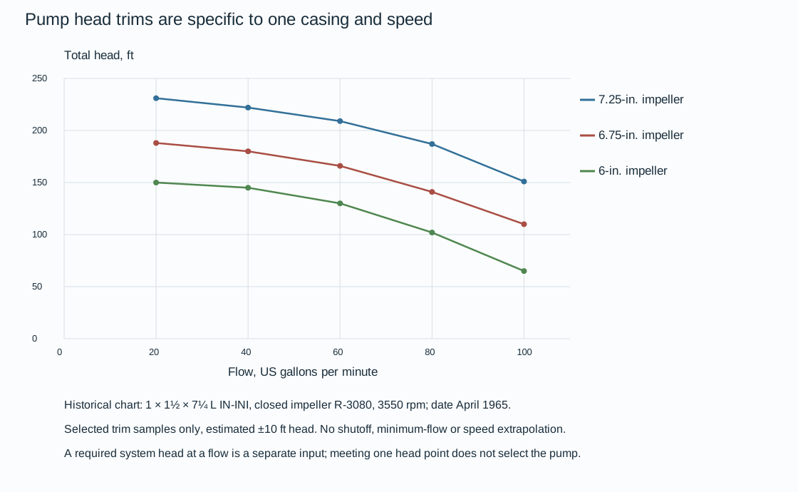
Figure 5.1. Approximate selected readings at 20–100 US gpm on three impeller trims of one 3550-rpm chart. Straight joins interpolate only between saved samples on the same trim. They do not apply affinity laws or create untested trims. The author-estimated head reading allowance is ±10 ft. No shutoff or minimum-flow acceptance is recovered.
For a hypothetical required duty of 60 US gpm at 185 ft of system head, the recovered curves give:
- Approximately 209 ft at the 7¼-inch trim;
- 166 ft at 6¾ inches;
- 130 ft at 6 inches.
The larger trim exceeds the assumed required head at this flow. The other two fall below it even within the stated graphical allowance. That comparison identifies a candidate for further duty evaluation. It does not make 60 gpm the operating point: the actual intersection with the complete system characteristic still determines the duty. Do not use excess head to justify an unexplained restriction or another speed without its performance basis.
Efficiency and power refine the same comparison. For the maximum trim at 60 US gpm and approximately 209 ft, the graphical efficiency is about 52%. The author-estimated allowance is ±3 percentage points. In customary units, the linked power calculation is
In these equations, is hydraulic horsepower, BHP is shaft horsepower and SG is dimensionless liquid specific gravity. The efficiency is a fraction. Enter 52% as 0.52. At SG 1.0 this gives hydraulic power about 3.17 hp and BHP about 6.09 hp. Combining the head and efficiency reading allowances gives an illustrative BHP range of about 5.5–6.8 hp.
The original power-contour labels include 3, 5 and 7½ BHP. The calculated 60-gpm point lies between the 5- and 7½-hp levels. The native power series is calculated from recovered head and efficiency rather than claimed as a digitized continuous BHP contour family.
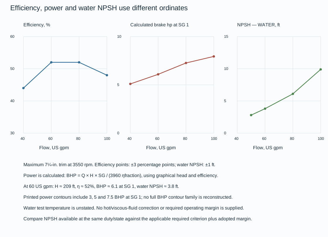
Figure 5.2. Maximum-trim efficiency readings, calculated BHP at SG 1.0, and separately recovered WATER NPSH readings. The different ordinates retain their units. Curve identity, selected head/efficiency/NPSH readings, power calculations and limitations preserve the basis; drawing implementation regenerates the native figures. These are historical graphical quantities with stated reading allowances, not equipment guarantees.
The WATER NPSH trace gives approximately 3.8 ft at 60 US gpm and 9.9 ft at 100 US gpm, with an author-estimated ±1-ft reading allowance. A required head check therefore cannot substitute for a suction check, particularly when the duty flow changes. For the actual inlet pressure, elevation, vapor pressure and suction loss:
- Compare NPSH available against the applicable required criterion and adopted margin at the same flow and fluid condition.
The water trace does not itself state an acceptance margin or a hot-liquid correction. A hypothetical available NPSH of 3 ft at 60 gpm is below the nominal 3.8-ft trace reading. The approximate chart cannot establish adequacy near that crossing. Resolve current vendor data, the applicable criterion and the actual suction state before selection.
Fluid changes also reopen power and efficiency. Holding head, flow and efficiency fixed would make calculated BHP proportional to SG. This does not prove unchanged head and efficiency curves for a viscous or otherwise different liquid. The original SG-1 power note and WATER NPSH label must remain with their data. A changed speed, impeller, inlet state or system resistance requires the appropriate equipment and hydraulic evaluation. Carry the selected duty and its remaining data needs into the equipment, driver, piping and support interfaces instead of relying on one favorable pressure-head reading.
A catalog size is a route to the correct data, not a description of every installation with the same nozzle diameter. One pump family identifies a size by discharge diameter, suction diameter and maximum impeller diameter, together with a series designation. Its performance curves then distinguish speed and impeller sizes within that family. Its outline data distinguish the motor frame, shaft extension, seal or packing arrangement and baseplate. Follow the connection between those identities. A curve belonging to one impeller or speed cannot silently supply the duty of another assembly.
Changing route resistance can change flow, efficiency, shaft demand and suction requirement. Do not carry the previous duty's efficiency into the revised duty without the selected performance basis.
A preliminary range chart can identify a family in which the desired head and flow may lie. It cannot supply the individual performance curve needed for final selection. The outline belonging to that family is another preliminary aid.
The selected driver frame can change the base length and shaft elevation. The selected seal can change quench, drain and recirculation connections. Water cooling can add an inlet, outlet and clearances that an air- or fan-cooled arrangement does not need. The drawing's optional, plugged and supplied connections must be interpreted as actual configuration choices, not as a list of every nozzle to connect identically.
Reconcile duty, machine/impeller/speed and driver requirements with nozzle coordinates, shaft height, baseplate, auxiliaries and removal envelopes.
A change to a larger motor frame or water-cooled bearing can invalidate a satisfactory foundation or utility route without changing the process line's nominal size. A certified outline therefore closes a specific provisional geometry. It is not a replacement for checking the affected connections and work envelopes.
The bearing variants illustrate the service consequence. In one horizontal pump family, a fan-cooled bearing serves a lower-temperature arrangement, while a water-cooled bearing is provided for higher pumping temperatures. In that particular bearing arrangement, cooling water enters at the lower tapped connection and leaves at the upper one. That flow path belongs to the selected bearing/jacket arrangement. It does not mean every pump needs cooling water or that a generic plant temperature chooses the variant.
The source of cooling, return condition, flow and readiness have to serve the actual machine. Loss of that cooling becomes another operating state for the equipment and its connected system.
A vertical pump adds a column and shaft arrangement to the choice. Oil and fresh-water lubrication alternatives are distinct in the illustrated multistage family. Its packed tension-nut detail is for fresh-water lubrication, and an additional column is a specific option.
That family's rating sheet also calls for efficiency reductions of 2, 1.5, 1 and 0.5 points for two, three, four and five stages respectively. These are local rating adjustments for that family, not a universal relation between stage count and efficiency. Keep them with the exact rating data and interpretation before a shaft-power calculation. A percentage-point reduction is different from multiplying efficiency by a percentage reduction.
Carry the selected lubrication, stages and column into the handling and pull-out arrangement.
The pump's auxiliary connection map should distinguish the function and medium of each selected circuit. Cooling water can remove heat from a bearing, stuffing-box region or high-temperature support pedestal. Its outlet is a cooling return.
Mechanical-seal circulation has a different path. In a selected process-derived arrangement, fluid taken from the pump case passes through the seal circuit. It returns to the pump stream or through the seal into the pump's internal clearances. In an external-medium arrangement, a separately supplied compatible clean fluid serves the selected seal duty. A clean gas oil is one hydrocarbon-service example, not an approved fluid for every seal or pumped product.
Gland quench, lantern-ring flush and seal circulation are not synonyms for bearing cooling. Their connections cannot be completed by attaching the nearest available water supply. Establish the actual medium, pressure and temperature, inlet source, required function and permitted outlet for each selected circuit. A vendor harness can cover some connections while plant piping covers others. Reconcile both drawings and the system diagram so a required connection is neither omitted nor duplicated. The pipe's small size does not make its loss of function unimportant to the machine.
Keep drains and leakoffs separate from those utility returns. The pump case vent and drain, stuffing-box drain and baseplate drain have different origins. A steam-driven installation can also have valve-stem leakoff and a steam-chest drain. Identify their collection or disposal conditions and the actual isolation/maintenance state. A pipe leaving the equipment is not automatically a cooling-water return.
Above-grade supplies in an illustrative layout also do not exclude a buried utility system. The selected connection must remain accessible and serve its actual source and destination. Utility loss, shutdown and restoration should be evaluated for the configured circuits, rather than inferred from the presence of a completed harness.
A common spare introduces a further configuration. When the middle of three pumps serves either of two duties, an arrangement based on the larger duty can provide a practical common machine. In that arrangement, top-suction geometry can simplify its routing. The spare still has to serve both actual fluid, pressure, temperature and performance conditions.
Its selection is not established by maximum volume alone. Describe how the suction and discharge connections select the intended service and how the inactive path is controlled. Different process compositions or operating pressures can turn a convenient shared route into an unacceptable cross-connection unless the selected configuration preserves separation.
A concrete common-spare topology makes the service-selection problem inspectable. In the considered arrangement, the service-B suction joins the service-A line downstream of its block valve and upstream of the common strainer. On discharge, the service-B branch joins downstream of the common check valve. Either selected suction therefore passes through the shared element, pump and discharge check before reaching the selected outlet branch. Selection has to occur on both sides of the machine. Changing only its inlet can deliver the right fluid to the wrong destination.
Table 5.1. Communication to establish for a two-service common spare.
| Defined state |
Intended suction and discharge path |
What the actual configuration must establish |
| Serving duty A |
A source → shared strainer → spare → common check → A destination |
Required A duty and compatible supplies; B does not form an unintended communication path |
| Serving duty B |
B source → shared strainer → spare → common check → B destination |
Required B duty and compatible supplies; A does not form an unintended communication path |
| Unavailable for maintenance |
Selected intervention boundary; spare removed from both service duties |
Actual isolation, depressuring/draining, remaining support and restoration basis; neither duty credits unavailable spare capacity |
| Transition between duties |
Controlled change from one defined path to the other |
Actual contents, compatibility, pressure and thermal states, valve selection and readiness; no unexamined overlap between services |
This table defines engineering questions for the selected topology, not an operating valve-lineup procedure or an automatic interlock design. The common check serves its selected reverse-flow function. It does not choose the suction source or discharge destination and does not establish complete maintenance isolation. Check the actual block valves, available utilities, control and transition arrangements in the complete system. A common spare can reduce installed equipment while making those shared interfaces consequential to both duties. Structured state data.
Pressure-boundary identity belongs in the same data chain. A selected pump can have suction and discharge nozzles of the same rating. Its manufacturing test exposes both sides to a common test pressure. This can apply even where the adjoining suction line has a lower class. That example explains why normal suction pressure alone may not determine the nozzle connection. Establish the actual machine's manufacture/test and maximum-pressure basis, flange face and class at the connection.
It supplies no universal equal-rating or test-factor rule, and says nothing about acceptable piping force or moment. The terminal-load account below remains a separate evaluation.
Suction conditions decide whether the liquid reaches the impeller usefully
Suction piping is not simply the low-pressure half of the installation. It supplies liquid in a condition that the pump can handle. Elevation and vessel pressure can provide head, while piping resistance consumes it. Liquid vapor pressure depends on its condition. If local pressure falls sufficiently, liquid can form vapor. Subsequent collapse of vapor bubbles as pressure recovers can cause noise, loss of head and capacity, and damage near the impeller inlet.
Entrained gas and trapped gas pockets can also interfere with liquid delivery, but should not be confused with the particular vapor-bubble mechanism of cavitation.
Available net positive suction head describes the system's head above the liquid vapor-pressure condition at the selected pump reference. Required NPSH is a property of the selected pump under its specified test and operating basis. They are different quantities. Increasing available head by changing vessel elevation or reducing suction loss does not change the supplier's requirement. Changing the pump or duty can change that requirement.
For a large vessel feeding a pump, the following available-head account assumes negligible velocity at the liquid surface and uniform liquid density:
In this equation:
- is absolute pressure above the liquid;
- is liquid vapor pressure at the evaluated temperature;
- is liquid density;
- is gravitational acceleration;
- is liquid-surface elevation;
- is pump reference elevation;
- is suction-system head loss to that reference.
With pressures in Pa, density in kg/m³, in m/s² and elevations and loss in meters, available NPSH is in meters of that liquid. The pump reference and evaluation convention must agree with the supplier's required-NPSH data. A vertical pump can place the relevant inlet reference below the visible driver elevation, so use the actual machine arrangement.
The equation makes a layout decision inspectable. Higher surface pressure or liquid level can increase available head. Higher vapor pressure or suction loss reduces it. A low operating level can therefore be more important than the vessel's maximum level. A warmer condition can consume suction margin even with unchanged piping. A dirty temporary strainer can increase loss without changing the nominal line size.
Over the applicable operating range, compare available head with the selected pump's requirement and adopted margin or acceptance basis. Do not copy a vessel-height example as though static height were the only contribution. Surface pressure, vapor pressure, loss, operating level and the pump datum remain part of the method. A short suction route is advantageous when it reduces loss without defeating flexibility, access or another service requirement. Vessels and equipment interfaces supplies the connected liquid-level and equipment-elevation context.
Suction and discharge arrangements have different priorities
Locate the pump and suction source so that a practical, short route can serve the required inlet condition. Avoid unintentional high points that retain gas and arrangements that unnecessarily consume suction head. Reducer orientation, elbow approach and the selected nozzle direction should be reviewed as a fluid path, not only as a collision problem. End-suction, top-suction, side-suction and vertical arrangements require different approach geometry and support.
A larger connecting line can be appropriate even when the pump nozzle is smaller. The piping size follows service loss, flow and mechanical needs. The nozzle follows the selected machine. Make the transition with the intended flow condition and access in mind.
A nozzle mismatch does not mean the machine should automatically be redesigned. It also does not make a reducing flange always an acceptable substitute for a gradual transition. Preserve the supplier and service requirements at that interface.
Close suction and discharge nozzles can cause the adjoining piping envelopes to collide. Compare offsets and reducers together. A suction offset can add loss and disturb the approach. A discharge arrangement may offer more freedom for that particular installation. This is a conditional routing comparison, not a rule permitting every discharge offset or forbidding all suction changes. Check the actual pump outline, line sizes and hydraulic and mechanical consequences before fixing the arrangement.
Suction valves and strainers also influence space and pressure loss. A conical strainer can require a spool long enough to insert and remove it. A flat or basket form has a different envelope and flow area. A tee-type temporary strainer can provide an alternative removal route.
Provide physical access to install, inspect and remove the selected type. Include the piping or flange intentionally opened. A drawing showing the strainer symbol does not establish that the element can be withdrawn.
Select the strainer with its removal path and suction condition
A temporary strainer creates a tradeoff between protecting the impeller and preserving the liquid delivery on which the pump depends. Its useful flow area, particle-retention requirement, clean loss and expected debris loading belong with its pressure boundary and withdrawal envelope. A plate that fits between the flanges can be mechanically convenient while presenting a restrictive flow path. A longer basket or cone can offer more perforated surface while requiring space inside the adjoining spool or fitting. A suitable clean arrangement can become hydraulically unfavorable as debris fills it.
One particular flat-plate pattern uses 5/16-in holes on 7/16-in staggered centers and is described as having 46% open area. That pattern illustrates the limitation of a flat element. It does not prescribe a particle size or establish the loss of every flat strainer. The basket and conical families considered here instead offer short and long elements labeled 150% and 200% open area. Their increased surface is obtained through three-dimensional geometry and length.
Establish what area the selected product's ratio references before comparing those labels with a flat-plate perforation percentage. Neither a catalog percentage nor a gross vessel opening supplies a pressure-loss coefficient for a clean or fouled element. The selected duty still needs the actual mesh or holes, flow, liquid condition and permitted suction loss.
Table 5.2. Strainer geometry changes the flow and intervention problem.
| Form |
Geometry and interface to establish |
Consequence for selection and removal |
| Flat plate |
Perforated plate and actual mating flange-face arrangement |
Short axial envelope; limited perforated area can be rapidly restricted by debris |
| Basket |
Extended perforated body, attachment ring, diameter and length |
More surface needs room inside the adjacent pipe; withdrawal can require opening and moving a spool |
| Conical |
Cone length, ring, fitting clearance and selected mesh or perforation |
A cone may not fit between an elbow and nozzle flange without a suitable spool; check the insertion as well as withdrawal path |
| Tee-mounted element |
Element and guides within a tee or body, access blind and drain arrangement |
Withdrawal through the access opening can leave the pump-side connection assembled; the access branch and lifting/handling space remain necessary |
Flange compatibility is part of this choice. The considered basket, cone and plate details distinguish flat or raised faces from ring-joint mating arrangements. Their ring and rebate construction cannot be exchanged simply because nominal pipe size matches. Use the specified flange face, class, gasket and element attachment together. A flange joint used to retain a temporary element also needs its restored arrangement defined for the state after the element is removed.
Now consider the actual break-out task. At an end-suction pump, a cone can need additional axial room between the elbow and weld-neck flange. Determine that space from the selected element rather than treat an illustrative spool length as a general minimum. If removal requires disturbing an inline spool, establish:
- Which flanges open;
- How the spool and remaining piping are carried;
- How the pump connection is restored without forcing alignment.
A tee-mounted strainer offers an alternative: removing an access blind permits element withdrawal while the main connection remains assembled. That can avoid one source of realignment work, but does not eliminate isolation, depressuring, draining, element handling or inspection of the opened boundary.

Figure 5.3. Authored conceptual intervention layouts after the selected isolation, depressuring and draining procedure. The inline element is removed with a break-out spool. The tee element is withdrawn through an access opening. Supports and isolation devices are not a completed design in these schematics. The choice changes which assembled alignment and load paths are disturbed. Structured data.
Monitoring and removal should follow the startup condition. Debris capture protects the machine while increasing the element's resistance. A loss increase can consume available suction head even when vessel level and line size remain unchanged. Use the selected monitoring and intervention basis, with the inlet and outlet measurement locations identified where differential pressure is used.
Replacing a temporary element after cleaning, removing it permanently, or retaining a permanent strainer are different configurations.
Record which was restored and check the intended flange, support and inlet path. Calendar time alone does not establish that debris loading or removal conditions are acceptable.
Discharge piping must serve the pressure-producing side of the system. Check and block valves, pressure measurement and any required recirculation or protection have distinct functions. A check valve can limit reverse flow in its selected application but is not automatically a complete isolation or protection system. A pressure indication upstream of an intervening valve can describe a different state from one downstream.
Components and joints, pressure protection and measurement and control develop those functions. Their positions and access have to work in the actual equipment arrangement.
Cleaning and readiness and operating integrity develop the startup and restoration basis.
Hot piping requires a coupled hydraulic and mechanical decision
Hot suction piping can be hydraulically attractive when short and direct but mechanically unfavorable when it cannot accommodate relative movement. Additional elbows and length may provide flexibility while increasing loss. Increasing diameter to reduce that loss changes stiffness, weight and the nozzle interface. The arrangement must be reevaluated after the change. A previous flexibility result does not apply unchanged to a revised line size.
Begin with the equipment and system movements, not only the fluid temperature. The pump, connected vessel and header may move differently. A common header can be hot while an idle pump branch remains colder. The combinations depend on operation. Evaluate the applicable branch and standby states. Do not assume both pumps and all connecting pipes always reach one uniform temperature.
Support placement changes both dead-weight loading and movement freedom. A support near a nozzle can relieve weight and its bending moment, but a restraint at that point may oppose thermal displacement. A support farther away may allow more flexibility while leaving a longer unsupported mass near the terminal. Flexibility and loads and support and restraint decisions evaluate those consequences. This chapter supplies the actual machine, piping geometry and operating states that the evaluations must represent.
Special arrangements, including selected spring-mounted equipment, can permit particular movement paths. They also change the machine's support and alignment interfaces. Do not treat a moving support as a generic cure for hot piping. Establish the supplier's permitted movement and nozzle conditions, the foundation and driver interfaces, and the actual cold and hot configurations. An arrangement that accommodates vertical growth may still be unsuitable for horizontal relative movement.
Recheck suction loss/available head and pipe/terminal behavior after any route, diameter, equipment-position or support change. Preserve one evaluated geometry, restraint configuration, equipment movement and installation-setting basis.
Standby changes a slurry suction line's fluid state as well as its temperature. A large flexible loop can provide needed movement while increasing the length that remains dormant when its pump is not running. In that branch, the normal flowing condition no longer explains how solids or deposits will accumulate or how the line will be returned to service. Keep the dormant volume and service behavior in the comparison alongside nozzle loading and flexibility.
One selected hot-slurry arrangement separates the vessel bottoms outlets for the primary and standby paths early in the vessel design. This reduces the shared dormant branch that a long common suction arrangement would otherwise create. That is a joint vessel, process and piping-layout choice, with its outlet geometry carried into the basic equipment specification. It is not a general instruction to add a nozzle or split every suction line. The resulting branches still need their actual hydraulic, thermal, support and nonoperating-state evaluation. Under the selected service basis, establish stagnant volume, heating/draining and standby readiness for each path.
A shorter dead leg is useful only while the revised route preserves the required inlet and movement conditions.
Pressure rating does not establish nozzle-load acceptance
Pressure containment, piping loads and machine alignment are different questions. A pump nozzle flange can match a pressure class while the connected pipe transfers unacceptable force or moment to the machine. Dead weight, thermal movement, support reactions, settlement and dynamic effects can all influence terminal loading. The load path continues through the nozzle and casing to the machine and supporting arrangement.
Use the selected machine's allowable-load basis and applicable project criteria. Generic preliminary force estimates can help layout development, but they do not become manufacturer acceptance simply because they use the same units. Force-only limits do not describe a complete force-and-moment interaction. The formal evaluation needs the applicable directions, combinations and equipment conditions. Mechanical analysis develops that comparison. This chapter keeps it connected to the machine being installed.
An integral inline pump and driver can reduce some relative-alignment interfaces compared with separately mounted equipment. That feature does not mean piping loads and movement are unlimited. Horizontal, vertical and multistage forms still need their actual support, removal and supplier requirements. Preliminary envelope data can support early studies, but final connections and maintenance dimensions should reflect the selected equipment.
Installation should preserve the configuration that was evaluated. Forcing a misaligned pipe connection into place can load the machine before it operates. An intended cold-spring arrangement, where permitted and specified, is a different engineering decision with an evaluated geometry. Where the governing basis prohibits cold spring or reserves it to owner approval, follow that restriction before selecting an installed prestressed geometry. Adjustable supports and construction spools should accommodate their defined erection purpose without silently introducing another prestressed state. Recheck an actual field alteration that changes support location, route or restraint.
The maintenance state also changes the terminal arrangement. Removing a strainer spool, a valve or compressor cover can remove a support path or expose a partly connected assembly. Define how the remaining pipe and the item being removed are carried. Correct operating nozzle loads are not proof of stability during partial disassembly. Work envelopes and constructibility and intervention and modification develop the associated spatial and work decisions.
The driver adds its own utility and removal interfaces
An electric motor requires the selected electrical supply and equipment arrangement, with any specified cooling and the access needed to maintain or remove its parts. The motor envelope, weight, coupling and removal task belong with the pump or compressor arrangement. A shaft-power calculation at the pump boundary does not supply the motor's electrical input, starting behavior or permitted operating range. Use the selected drive and transmission information to connect those quantities.
A gas-turbine driver has air-intake, fuel, exhaust, lubrication and maintenance interfaces different from a reciprocating gas engine.
Hot exhaust can be part of a selected heat-recovery arrangement, introducing a connection to steam generation or another heating service. That possibility does not supply the actual exhaust temperature or a heat-recovery duty. Establish the selected driver's exhaust and operating basis and coordinate any recovery equipment as another system interface. Available fuel, utilities, climate and maintenance access influence the drive choice alongside performance and lifecycle cost.
A different driver can also change the installation's response to utility loss. An electric supply failure and a steam-supply interruption are different initiating conditions. A spare machine with another driver helps only if its own supplies and startup arrangements remain available. Describe the intended transition in the operating basis rather than infer reliability from the number of machines. The steam-driven standby arrangement illustrates this issue directly.
A steam-turbine driver needs a ready steam system
A steam turbine converts the supplied steam's energy into shaft work. For the small steam-driven equipment arrangements considered here, the inlet, governing system, exhaust, drains and lubrication interfaces are part of its readiness. A mechanically available turbine can still be unavailable as a standby driver. This can occur if its steam supply contains accumulated condensate or its exhaust path is unsuitable.
Keep inlet steam in the condition required by the selected turbine. Liquid reaching a rotating turbine can damage its blades. Standby service makes drainage particularly important because live upstream steam can condense while the turbine is idle. Inlet strainers protect against scale, weld debris and other solid contamination. Their selected removal arrangement must remain accessible. The strainer and condensate controls solve different problems, so one does not establish the other.
Manual and automatic startup arrangements place different demands on the inlet system. In a manual arrangement, the selected block and drain/trap arrangement should allow the operating action without carrying accumulated liquid into the machine. An automatic-start arrangement adds an automatically operated admission valve and must preserve readiness during standby. Where the selected system includes a warm-up bypass, its flow path and operating purpose must be defined. Do not universalize a historical bypass size or assume that an open bypass supplies every required warming or drainage function.
Casing and gland drains or leakoff connections have their specified destinations and pressure conditions. A drain discharging near atmospheric pressure may not have the differential pressure that a particular steam trap requires. A connection meant to remain open cannot acquire an isolation valve merely because standard small-piping details commonly include one. Use the selected machine's connection information and the applicable service arrangement. Steam and utility systems develops trap and condensate-system selection, while this chapter explains why turbine state and connection pressure matter.
A sentinel valve and a pressure-relieving system perform different functions. The small sentinel connection described for a turbine should not be counted as adequate exhaust overpressure relief. The selected exhaust system needs its actual protective basis. That distinction avoids a superficially complete drawing in which a familiar valve symbol is credited for a function it cannot provide.
Exhaust piping may connect to a back-pressure steam system, a condensing arrangement or another selected exhaust destination. The outlet pressure and connected boundary influence turbine service. Protect the intended exhaust path from unintended blockage and keep its maintenance isolation arrangements identifiable. Locating an operating or maintenance valve changes the likelihood of inadvertent action and the access needed, but its preferred position depends on the selected system. Treat these concerns as a coordinated operating configuration rather than a universal valve-location rule.
Condensing arrangements link steam, vacuum and condensate removal
A condensing turbine adds a surface condenser and associated systems. Steam exhaust is condensed in an exchanger, while noncondensable gas must be removed to maintain the intended vacuum. The exhaust connection, condenser, air-removal equipment and condensate pump therefore form one functional arrangement with several different pressure and elevation interfaces.
The exhaust pipe can be large and can transmit movement and load to the turbine nozzle. A selected expansion-joint arrangement can reduce particular terminal forces, but it also needs the required anchors, guides and pressure-thrust treatment. It is not a free connection that removes all mechanical consequences. Coordinate the joint and support system with the turbine and condenser movement basis through analysis and supports.
A vacuum-operated condenser has a different relief and drainage problem from an ordinary positive-pressure utility line. Its selected protective device and water-seal or drain arrangements must work at the specified condition. In the illustrated water-sealed relief arrangement, the water supply and overflow are part of the function, not optional incidental plumbing. Preserve the selected supplier/system requirements and do not extend that particular arrangement to every condenser.
Condenser elevation affects the condensate-removal arrangement and available pump suction conditions. A grade-mounted turbine with a grade-mounted condenser and an elevated turbine exhausting downward can lead to different head, structure and maintenance choices. A vacuum system should not be assigned a generic condensate-pump elevation merely because the equipment fits in the drawing. Evaluate the actual liquid level, pressure, pump reference and losses using the suction-head method.
The combined arrangement also needs cooler and exchanger access, air-removal piping, drains and inspection space. A lower first-cost placement can require a different condensate pump or more removal work. Compare these consequences with the selected process and maintenance needs. Exchanger and vessel interfaces develops the thermal equipment. This chapter connects those interfaces to the driver installation.
Centrifugal-compressor casing and service determine its connections
A centrifugal compressor raises gas pressure through an impeller-based flow path. The selected machine may use multiple stages and can include intermediate discharge or sidestream connections. A casing or nozzle size reflects the manufacturer's flow path and mechanical design as well as the connecting process line. Equal nominal sizes are not an objective in themselves.
Develop smooth transitions at the selected suction interface according to the supplier and service requirements. A stock casing nozzle larger than the process line may require an appropriate reducer and flange arrangement. An abrupt restriction or an ill-considered change intended only to match sizes can degrade the inlet flow condition. Locate the compressor with attention to suction-route loss, line size/cost and maintenance access. The shortest route still has to accommodate movement and terminal loading.
Casing split changes the maintenance envelope. A horizontally split case opens upward, so piping over it may need break-out connections and a practical support/removal arrangement. A vertically split case requires the relevant end or front removal path. The crane, cover, rotor or casing movement and laydown path should be developed with the vendor outline. A piping route clear of the running machine can obstruct the very path needed to service it.
Tandem machines and different drivers add shared shaft, auxiliary and access interfaces. Steam-turbine, motor or gas-turbine selection changes the layout and utilities. Elevating a machine can help particular nozzle or condenser arrangements while adding structure and access work. A grade-mounted machine can use mobile handling but may require more removable overhead piping. The common layout method compares the whole work path. This chapter establishes which machine parts and service connections give the path its purpose.
Do not define thermal behavior from the name centrifugal compressor. Actual process temperatures, interstage cooling and special services determine the piping conditions. Regeneration can impose a temperature range quite different from normal production, even if it occurs infrequently. A large line at a moderately elevated temperature can still generate consequential terminal forces. Preserve the applicable normal, standby, regeneration or other defined states in the movement and nozzle-load basis.
Give the inlet condition enough space in the actual approach
The last elbow, valve or other flow-disturbing feature can make a compressor inlet different from an equally sized straight pipe. The approach direction relative to the shaft and the length before the inlet matter alongside velocity, gas composition and temperature. Establish the selected compressor's inlet requirement early enough to influence its elevation, underfloor clearance and nozzle arrangement. A line that fits a clearance check can still provide the wrong inlet condition.
A particular five-configuration illustration uses an inlet size in and a base straight-run dimension in, or 4 ft. Here is the stipulated diameter used by that illustration's rule. A project's diameter convention must be established before substituting another pipe or nozzle. The horizontal approach parallel to the shaft is the base case. A perpendicular approach and a valve-containing approach use 1.5 times the base dimension.
The perpendicular main approach with an offset before the riser uses 1.75 times it. The parallel main approach with an offset before the riser uses 2 times it. These differences are consequences of the illustrated approach configurations, not multipliers for every elbow or valve.
Table 5.3. Conditional inlet-run comparison for the illustrated 12-in, 4D basis.
| Arrangement |
Approach feature in the illustration |
Required dimension relative to |
Illustrative dimension |
| A |
Horizontal approach parallel to shaft |
|
4 ft |
| B |
Horizontal approach perpendicular to shaft |
|
6 ft |
| C |
Approach includes the shown valve |
|
6 ft |
| D |
Perpendicular main approach with offset before riser |
|
7 ft |
| E |
Parallel main approach with offset before riser |
|
8 ft |
The associated illustration gives horizontal pieces of 10D, or 10 ft for the stipulated 12-in size. Those horizontal dimensions are separate from the vertical straight section immediately below the compressor inlet. A requirement of 8 ft below that inlet can change floor or machine elevation appreciably compared with the 4-ft base case. Include the elbow, flange and support envelopes in the actual elevation study. Do not interpret either length as a complete floor-height dimension.
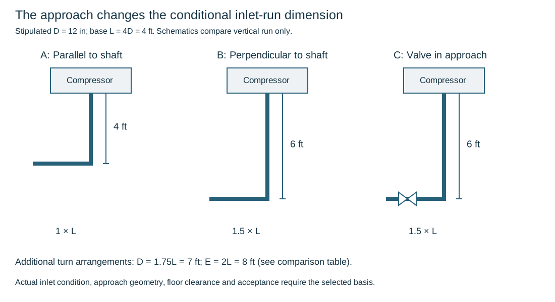
Figure 5.4. Three schematic elevation sections within the five-configuration illustration: parallel, perpendicular and valve-containing. The dimensioned vertical sections show the stated 4-, 6- and 6-ft comparison; Table 5.3 retains the remaining turn-arrangement factors. This is a conditional layout comparison, not an inlet-flow qualification or fabrication drawing. Structured data.
Keep the other inlet provisions on their own bases. A historical three-diameter power-test statement describes a different context from this stipulated four-diameter example. Neither supplies the selected machine's complete flow requirement. If wash water is injected to clean blades, the spray and gas mixing arrangement can require a longer straight section. One illustrated wash arrangement says that this could be 10 ft.
Its nozzle, injection duty and mixing requirements must be established with the machine and service, rather than inherited from a dry inlet.
A straightening vane is also an alternative with conditions. In the particular procedure, a tolerable vane complying with the applicable ASME or American Gas Association basis can permit dividing an illustrated arrangement's length by four. That is not a general permission to shorten any inlet, nor evidence that a vane cures an unsuitable valve, turn or wash-water arrangement. Establish whether the selected compressor and service permit the device and what qualified geometry and performance basis applies. Compare rerouting, elevation change and the evaluated vane arrangement as actual alternatives, carrying their loss, inspection, cleanliness and maintenance consequences.
This account also applies to strainer and break-out location. A permanent inlet strainer needs a clean-out arrangement. A temporary element needs its intended removal state. Flanges at a nearby valve can provide a natural break. An otherwise continuous line may require another removable connection to clear a casing or element.
The break must leave a supported assembly and preserve the required operating approach when restored. Removing a spool for maintenance cannot permanently consume the straight section that was part of inlet selection.
Lubricating and seal systems are operating systems
A lubricating-oil system supplies clean oil at the required condition to bearings and associated equipment. A typical console includes a reservoir, primary and spare pumps, coolers, filters and controls. The arrangement also needs return paths, cooling and driving utilities, maintenance space and appropriate cleanliness. Its function is lost if any of those interfaces is treated merely as small-bore detail.
Gravity return can set console elevation and line routing. A high point, pocket or unsuitable return arrangement can interfere with drainage even when the supply pressure is adequate. Keep the oil reservoir, return route and machine connection elevations coordinated. In a cold environment, a selected reservoir heating arrangement adds another service and maintenance interface. A heating coil, cooler bundle or filter element needs its actual withdrawal space.
Primary and spare pumping arrangements should be understood in their operating and supply-loss states. The spare may have a different driver or startup mode, so power, steam or control availability can matter to its intended role. Describe what supplies the bearings during the transition rather than assume that two pumps automatically establish continuity. The specific control, reserve and acceptance requirements remain those of the selected installation.
Seal systems have another purpose and boundary. In an oil-sealed compressor arrangement, oil is supplied to the shaft-seal system under its specified pressure and temperature condition. Low-pressure returns and contaminated or sour-side oil can have different paths and treatment. Gravity and pressurized seal-oil arrangements need their own elevation, pumping and degassing interfaces. This treatment applies to the oil-sealed arrangements described here. It is not a statement that every compressor uses an oil seal.
A selected overhead seal-oil reservoir can preserve a limited supply when the pressure source is lost. Its static head, usable inventory and connection determine the reserve function. The manufacturer establishes the required arrangement and elevation for that machine. A historical elevation range is not sufficient to select the tank or establish its endurance. Level indication, access and maintenance also occupy space, and the reserve's limited duration should remain visible in the operating basis.
Auxiliary material and cleanliness requirements serve these functions. The selected oil system may require corrosion-resistant or otherwise controlled supply piping to avoid particles reaching critical equipment. The exact material and cleaning basis cannot be inferred from pipe diameter alone. Materials, utilities and cleaning and readiness develop those selections and verification. This chapter connects them to the bearing, seal, reserve and return functions they must preserve.
Reserve elevation for the actual oil return
Trace the gravity oil return from the equipment connection to the actual reservoir entry with its gradient, direction changes, sight-glass/manifold geometry and surrounding piping.
The reservoir's required volume and retention duty can affect its height. Raising it to resolve one clearance can consume the fall needed by the return. Raising the machine can restore that fall while changing foundations, platforms and maintenance access.
One particular return-layout detail distinguishes a minimum gradient of 1/4 in per ft from a planning gradient of 1/2 in per ft. These are separate criterion and layout inputs under that adopted detail. The historical reference to an API minimum is not a determination of the current edition's requirement for a project. For horizontal run length in feet and gradient in inches of fall per foot, required geometric fall is in inches.
This relation accounts only for straight-run geometry. It does not demonstrate adequate gravity flow, reservoir entry conditions or clearance for fittings, insulation and tolerances. Evaluate actual oil flow, viscosity/temperature, venting and return arrangement on the applicable basis. Do not turn the larger planning number into an unrelated acceptance limit.
This elevation account makes a later change inspectable. A replacement console, raised reservoir entry, new pipe crossing or different machine support height can change the usable return. This can occur even if its pipe diameter remains the same. Reconcile the actual equipment and console boundaries. Preserve the gradient, datums and filled/cold/operating assumptions in the layout and handover record.
Structured method data. Elevation and work envelopes evaluates the surrounding space. The return must still deliver the lubrication system's operating function.
Reciprocating compression introduces cyclic gas and mechanical behavior
A reciprocating compressor imposes cyclic gas flow. Single-/double-acting chambers, cylinders, stages and driver arrangement change the pulsation, foundation, access and piping interfaces. Average flow and final pressure do not describe the cyclic system.
Liquid carryover is a different problem from gas compression. A liquid slug can impose a severe mechanical demand because the cylinder is designed to compress gas. Suction separation and drains consequently have a protective role as well as a process role. A suction vessel or separator should deliver the required gas condition while collecting liquid. Its level observation, control and protective responses need to match the selected service and operating arrangements. A manually drained example should not be copied into a wet-gas service without evaluating the different accumulation rate and required response.
Interstage cooling can condense liquid, adding separation and drainage interfaces between compression stages. Some machine arrangements place coolers or connections directly over a cylinder and can differ from the common suction-from-top/discharge-from-bottom layout. Use the actual selected arrangement rather than turn one nozzle orientation into a universal rule. Vessel and exchanger mechanisms and level measurement and control develop the connected functions.
A drain must discharge into a compatible pressure state
Interstage drainage is not complete when every low point has a drain symbol. A multistage compressor has connected regions at different pressures. Connecting a lower-pressure drain to a header maintained at a higher pressure can drive header liquid back toward the lower-pressure cylinder. The intended protective drain has then become a carryover path. A downward pipe route does not by itself overcome the pressure difference.
Compare the pressure at each drain connection with its receiving system in the relevant operating, startup, shutdown and isolation states. Include liquid head and the selected drain or control behavior, rather than compare only the normal stage pressure. A header connected to another running stage can remain pressurized while a stage or machine is idle. A shared header may therefore have a different pressure state from the machine whose drain is being considered. Establish what prevents reverse communication where a pressure difference can reverse the intended flow.
A generic check valve or steam trap is not automatically the appropriate solution for every liquid, gas and operating sequence.
A hypothetical equal-elevation example makes the pressure mechanism visible. Let a lower-stage connection be at 100 kPa gauge and a higher-stage connection at 500 kPa gauge. Let their proposed common drain header be at 300 kPa gauge. All use the same atmospheric reference.
Ignore liquid-head and line-loss contributions solely for this illustration, and assume a communicating open path. The higher stage has 200 kPa of pressure difference toward the header, while the header has 200 kPa toward the lower stage. This example shows possible direction. It supplies no flow rate, liquid inventory or adequate protective device.
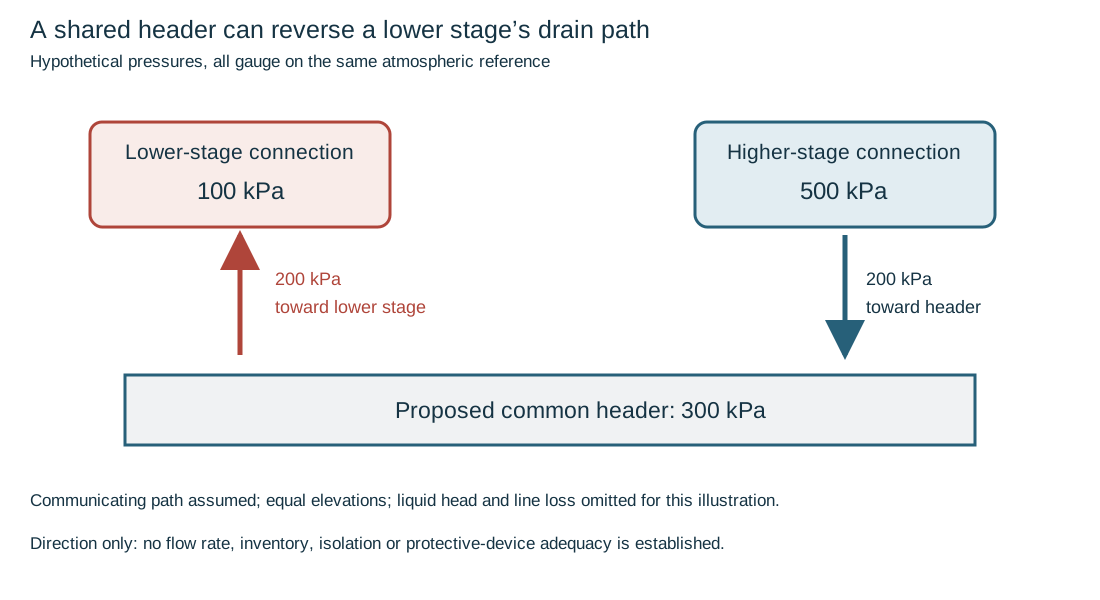
Figure 5.5. Hypothetical pressure-state illustration, with gauge pressures on one atmospheric reference and equal elevation. The indicated reverse direction requires a communicating path. Actual isolation, controls, liquid head and losses are not evaluated. Under these assumptions, the 300-kPa header opposes discharge from the 100-kPa stage. Gravity fall alone does not establish forward drainage. Structured data.
Process-liquid drains, stuffing-box leakage and distance-piece vents have different origins and destination requirements. Leakage collected between a compression cylinder and crankcase is not simply another interstage-liquid drain. A selected hazardous-gas service can use a gas-tight distance-piece arrangement and its defined vent or collection system. That example does not establish every compressor's seal construction.
Reconcile the actual machine and plant diagrams. Ensure leakage, gas release and process liquid reach their intended systems without an unexamined pressure connection. The operating and intervention procedure must preserve the isolation and restoration on which those functions depend.
Suction and discharge bottles and connected headers form part of the pulsating system. Temporary suction strainers can protect cylinders from solids during startup, but require a removable arrangement and a defined inspection/removal basis. Break-out flanges and lift access must leave the remaining piping and bottle supported. Neither a clean inlet nor a satisfactory pressure test proves that pulsation and structural response are acceptable.
Drivers add mechanical and utility requirements. A reciprocating engine can transmit vibration through its foundation and small auxiliary connections. Its fuel, intake, exhaust, cooling and lubrication arrangements need both their operating function and mechanical interfaces. A selected flexible connection may reduce transmitted motion but brings its own material, pressure, support and inspection requirements. Components and flexible connections and operating inspection provide the relevant boundaries. Generic hose is not a complete vibration solution.
Pulsation, span and restraint must be evaluated together
Cyclic flow produces pressure pulsation, and the mechanical piping responds according to its mass, stiffness, geometry and supports. Copying a nonvibrating installation does not establish the response of another machine or route. The relevant machine data, acoustic and mechanical behavior and support conditions need their own evaluation. A thermal-flexibility arrangement can be dynamically unsuitable. Adding restraint for dynamic response can increase thermal or terminal loads.
A historical support-location method makes the necessary inputs visible. It first sets the route and identifies corners, intersections, elevation changes and concentrated masses. A supplier-dependent design natural-frequency input is then used with tables whose support boundary conditions are specified. Corners/intersections and straight runs are treated with different models. Finally, support positions are coordinated between adjacent lines and common piers. The method's usefulness is not a universal span number but its explicit connection between geometry, mass, boundary condition and the chosen dynamic criterion.
For a bounded educational lookup, consider the table basis for a cantilevered corner or intersection with a hold-down at one end. The NPS 3 row lists maximum schedule XX. Its tabulated frequency values are 202 cycles/s at a 2-ft span and 90 cycles/s at a 3-ft span. The associated example selects a table value nearest to, but not less than, 140 cycles/s. Under that particular lookup criterion, 2 ft passes the frequency comparison while 3 ft does not:
Table 5.4. Bounded cantilever-frequency lookup.
| Candidate cantilever span |
Tabulated value |
Comparison with the example's 140-cycles/s minimum |
| 2 ft |
202 cycles/s |
At or above the lookup criterion |
| 3 ft |
90 cycles/s |
Below the lookup criterion |
This comparison does not establish a safe span for a new compressor installation. It retains the table's pipe/schedule and support model, and treats 140 cycles/s as the example input, not a general compressor speed or universal natural-frequency requirement. Other support boundary conditions use different tables. Actual gas pulsation, clamps, coupling moments, contents, thermal movement and the selected project/machine criteria are not supplied by this two-row comparison.
Hold-down hardware also has a defined behavior. A selected spring or resilient element can maintain contact while allowing a particular thermal movement. Over-tightening a resilient washer until it loses its intended resilience can defeat that function. A support under a warm discharge bottle may require a specific installation and operating adjustment sequence. Use the selected detail and supplier instructions. Do not merge a historical wedge-setting sequence with a different restraint system into a universal startup action.
Turn local support decisions into a coordinated compressor layout
A reciprocating-compressor support layout develops through three related decisions. First locate the candidate weight and restraint points at corners, intersections, elevation changes and concentrated masses such as valves. Align neighboring lines with a common pier where practical, while retaining each line's own movement and load conditions. The candidate locations are not yet a completed spacing or dynamic design. Obtain the compressor supplier's selected design-frequency basis and the applicable pulsation/mechanical evaluation before using a frequency-based span lookup.
Resolve the evaluated hold-down location near the header, permitted cantilevers and remaining straight-run lengths.
A corner arm and a straight run have different boundary models. A hold-down limits uplift through its defined hardware stiffness and setting. It need not be an axial anchor or a fully fixed rotational end.
Resolve access around valves. Do not transfer an assumed restraint direction into the thermal model solely to improve a frequency estimate.
Finally work through the straight runs beginning with the smallest selected line, which can require the most support stations. Add intermediate rests and evaluate whether neighboring lines can share the underlying pier without forcing all their contacts or restraint stations to coincide. The selected layout procedure offsets intermediate supports rather than making every adjacent span equidistant. Its illustrated minimum offset is 3 in. That is a condition of that procedure, not a universal spacing cure.
A common pier can carry independent rests and hold-downs with different local positions and freedoms. Carry the summed static and dynamic reactions into its structural design.
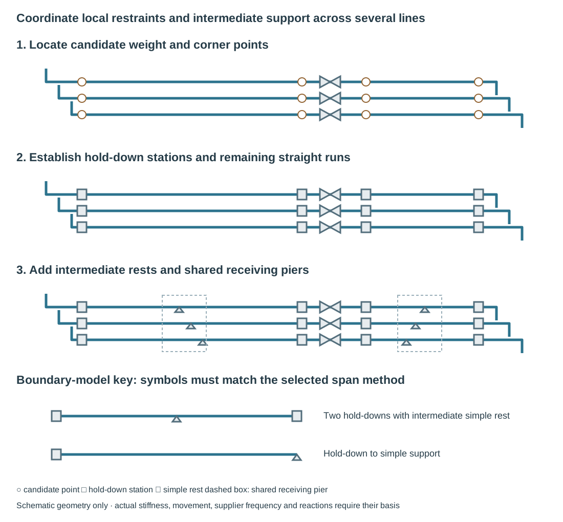
Figure 5.6. An authored schematic sequence uses the same three lines through candidate local points, established hold-down stations and added intermediate rests on shared piers. No source spacing or design frequency is encoded. The boundary key distinguishes the selected two-hold-down/intermediate-rest model from one hold-down with a simple support. Their span symbols belong to their own methods. Structured layout constraints retain those distinctions.
The selected two-ended arrangement has hold-downs at both outer ends and an intermediate simple support. Its tabulated L is the subspan from that simple support to the right-hand hold-down. The entire interval between the outer hold-downs is not labeled L. The corresponding one-ended method addresses a hold-down-to-simple-support interval. Their tables are different.
The two-ended source sketch also marks the left subspan as at least 6 in shorter than L, a separate condition from the 3-in inter-line offset. Preserve that unequal-span convention if adopting that lookup. The schematic key supplies no lengths.
An intermediate rest changes weight contact and effective span while allowing the separately defined movements. Calling it a second hold-down would apply the wrong model.
Establish the actual contact and restraints before selecting any numerical row.
Damaged or blank cells are not zero or implied acceptance. The historical example's supplier frequency, table limits and drawn dimensions are not default values for another compressor installation.
Review the assembled layout with the actual thermal and operating response, rather than declaring the third panel complete by appearance. Changes to one pier can affect several lines. A dynamic restraint can oppose growth, and lift-off can remove an intermediate weight support. Check valve/bottle removal and test loads as well as normal service. Keep the support sequence tied to span and weight modeling and direction-specific frequency modeling. The qualified supplier and system analysis supply the actual acceptance basis.
Preserve thermal freedom while setting the selected restraint
The illustrated metallic hold-down family restrains upward and downward movement while permitting sideways and lengthwise movement. It is therefore not a three-direction anchor simply because it appears rigid on a drawing. Its displayed temperature range is 40–650°F, and its application still needs the prescribed pipe, bearing and vibration basis. A different clamp or support criterion can assign different freedoms. Keep the actual detail in the mechanical model. Do not generalize one family's permitted lateral motion to a system requiring transverse restraint.
A resilient compression washer loses its intended function if installation flattens it permanently. One particular installation procedure begins with finger-tight nuts. It then uses a 45° wrench turn for 1½–3-in sizes and 90° for sizes 4 in and larger. Those turns are instructions for that selected detail and procedure, not general bolt torque values or a substitute for the required washer/load capability.
The smaller ¾- and 1-in variants also carry a specific stress-approval condition in the illustrated family. Set and verify the actual assembly under its governing instructions. Appearance or nut tightness alone does not prove the intended resilient reaction.
An adjustable spring wedge under a discharge bottle serves another state transition. The considered arrangement is installed with clearance and a loose spring before startup. After the connecting discharge leg warms and expands, it is adjusted to firm spring-loaded contact. Its position under the bottle's inlet and the independent cylinder support matter to that load path.
This is the selected wedge sequence. It must not be merged with spring-hanger release or generic clamp tightening into a universal warm-adjustment instruction. Keep capacity, permissible adjustment, startup condition and later empty or shutdown conditions with the device's identification.
Insulation changes the bearing envelope as well. The considered cold-insulated arrangements retain the insulation instead of cutting it back at the hold-down and use the specified cradle or load-transfer block. Insulation and cradle thickness change the required hardware fit. Ordinary bare-pipe size is not the completed outside bearing dimension.
Reassess the insulation's load-transfer and barrier duties, pipe movement and actual contact rather than close a clamp onto unqualified insulation. Support details and Insulation interfaces carry those material and thermal functions. The machine's vibration problem does not suspend them.
Dynamic and mechanical analysis and supports and restraints develop the quantitative evaluation and selected hardware. This chapter establishes why the reciprocating machine, bottles, route and operating states must be represented together. Operating vibration or an unexpected restraint condition is feedback into that basis, not proof that an arbitrary added clamp is the appropriate repair.
Preserve function through installation and intervention
Before an installation is ready, the intended fluid paths, auxiliaries and mechanical configuration must exist. Check the selected equipment and nozzle identity, connection orientation, removal spaces, supports, restraints, auxiliary returns and utility interfaces. A certified outline can invalidate a preliminary envelope. A changed strainer, valve operator or seal system can alter space, pressure loss, weight or maintenance. Reconcile these changes with the evaluated arrangement rather than make the piping fit by undocumented field adjustment.
Startup and standby require their own checks. A temporary strainer, a closed exhaust valve, a blocked spring or an undrained steam inlet changes the state. Verify the configuration required by the selected commissioning and operating basis, including restoration after cleaning or testing. Readiness develops that verification. Pressure-test completion alone does not establish:
- A clean oil system;
- Steam at the turbine inlet free of damaging liquid condensate;
- A dynamically acceptable compressor route.
Maintenance should follow the physical disassembly path that layout reserved. A horizontally split compressor may need overhead piping removed before its cover is lifted. A vertically split machine needs its end withdrawal corridor. A pump, filter, cooler or seal reservoir has another removal task. Identify the remaining pipe/support configuration and the means of handling the component. An operating installation that is stable and aligned can become a different mechanical system as connections are opened or masses removed.
Changing service or hardware reopens affected decisions. A denser liquid changes head-pressure conversion and power demand. Another temperature changes vapor pressure and movement. A larger impeller or speed change affects machine performance and downstream conditions.
Replacing a valve or rerouting a branch can change loss, mass, thermal freedom and dynamic response. Trace these effects through the machine, connected equipment, protection, supports and operating states. Use operating integrity, repair and modification and engineering records to preserve the actual configuration and reasons.