Chapter 22 — Engineering records, human factors and lifecycle decisions
A useful record explains the installed decision
An evaluated piping arrangement depends on actual component identity, service state, settings, geometry and support/contact conditions. A sliding guide differs from a loose attachment; a calibration reference differs from an uncorrected offset; a temporary filled test state differs from the service arrangement. The record must locate those physical distinctions, not only the line tag and pressure class.
A process diagram supplies function and connections; layout supplies position and working space; calculation supplies its model, loads and criteria; fabrication/inspection and as-built information supply what was made, examined and installed. A statement in one representation does not establish all these conditions.
A preliminary vendor envelope can support alternative equipment arrangements. It does not necessarily support final nozzle connections or a fabrication spool. Internally generated equipment information can be sufficient for a study while the selected supplier data is pending. When the confirmed outline arrives, compare the consequential differences rather than simply file it alongside the earlier assumption. A change in nozzle projection, weight, actuator height or withdrawal length can reopen several neighboring decisions.
An assumed removal envelope supports arrangement comparison but does not establish final withdrawal clearance. Preliminary line size can support routing while hydraulics and quantities remain unresolved. Final spool/connection dimensions require confirmed equipment data.
A certified drawing establishes a particular supplier representation and revision. Its status should not be extended into a claim that every connected pipe, support or operating task has been evaluated. Likewise, a calculation marked complete should retain its input identity and state. A later geometry or service change can invalidate its applicability without changing the calculation file itself.
Keep line identity and physical attributes consistent
Line identification allows process, piping, fabrication and operating participants to refer to the same intended service and route. A convention may combine unit, service, sequence, nominal size, material class, insulation and other information. Those fields have different meanings, and identification conventions vary. Adopt the actual project convention without turning one organization's syntax into a universal engineering rule.
The identifier is not a substitute for the physical data. A line can change size, class or other attribute along its route under a specified convention. A class break can require another identifier or a defined segment and exception. The adopted basis determines that treatment. Do not infer that every component sharing a line number necessarily has the same dimensions or allowable conditions.
Preserve where an attribute applies. A size or material entry must connect to the relevant segment or component. A nominal pipe size and schedule identify a selection category. They are not measured inside diameter or wall thickness.
A pressure class is not an operating pressure. Design, operating, upset and test conditions should retain their state and pressure reference, and a minimum temperature at pressure should remain paired with that pressure. Materials, pressure design and testing develop the technical use of these distinctions.
Units and meaning need to travel together. A pressure stated in psig, an absolute pressure and a pressure difference are not interchangeable records even when their numerical strings look similar. Force and moment require their respective units and directions. Fluid temperature, metal temperature and a thermal displacement can describe different inputs to one evaluation. A field named temperature without its state, location and purpose can conceal the condition that actually governs the decision.
Unknown, not applicable and zero also have different meanings. A missing equipment load limit is not a zero allowable. A zero imposed movement is an input, not proof that movement was never considered. Identify unresolved data and its effect on use rather than populate a blank with a convenient value. Keep significant precision and a declared conversion or rounding basis where it affects a result.
The selected service/class, component revision, valve mass, support state and calibration fluid/range must apply to the same physical segment across P&ID, line list, isometric, mechanical model and instrument record. Matching a tag alone does not establish that agreement.
Translate the convention without translating away the engineering
An identifier needs its namespace and dictionary. The same service letters can identify high-pressure steam in one convention and hydrogen sulfide in another. A letter used for clean condensate elsewhere can identify caustic. A shared character string is therefore not evidence of a shared fluid. When combining records from different units or projects, first establish which convention assigned the identifier and what each field means. Preserve the original reference alongside the resolved item rather than match records by an unqualified service code.
A composite convention can explicitly carry unit, service, sequence, size, schedule, material specification, insulation thickness and insulation purpose. Another can order these differently or omit a unit prefix inside a defined battery limit. A shorter purchasing identifier may point to a fuller specification. It does not itself contain that specification. Resolve the selected item and revision before using the code for procurement, replacement or analysis. A supplier can retain a catalog label while changing the supplied design, so the label must be checked against the actual required construction and service.
Trace identity through the physical route as well as across documents. A selected numbering scheme can retain one number across a reducer or a control-valve bypass. It can assign new numbers to branches or equipment connections and leave particular instrument connections unnumbered. Another adopted scheme may draw those boundaries differently.
Record the topology and the applicable size or class segments independently of the convention's number changes. A line number remaining constant across a reducer does not turn two bores into one hydraulic input. An unnumbered instrument connection remains a physical pressure path requiring its own design and restoration.
A resolved identity binds the original convention to a physical item/segment and its applicable fluid, material and allowable conditions. An unresolved service code or class exception cannot be treated as a confirmed engineering input. See components, flow geometry and sensing paths.
Spool/isometric information must define actual geometry, component/material identity, joint locations and dimensions for the selected shop, module or field-fit construction. Fabrication supplies those dimensional interfaces. A model clash check cannot detect an omitted work envelope or field-run connection, and quantities from an incomplete selection remain incomplete.
Instrument records connect the process function to device, range, connection, signal and receiving arrangement. Installation details and loop information can include the selected calibration, supplier model and input/output role. A later replacement or service change should be connected to those records, not treated as a new tag with the old loop assumed valid. Measurement and control supplies the sensing and mode basis.
Calculation and evaluation records need their own state and interfaces. Geometry, material, contents, temperatures, contact/restraint conditions, equipment movements and selected allowables should remain identifiable. Outputs should distinguish the result and its applicability from the criteria used to judge it. A stress result, a nozzle-load comparison and a supporting-structure check address related but different acceptance questions. Analysis and supports develop their physical evaluations.
A safety-critical item's credited protective function requires the actual scenario, performance basis and configuration; an equipment tag or filled SIL field does not establish capacity, independence or a test interval. Local criticality classifications are not universal exemptions from piping integrity. See protective systems and functional integrity.
Reuse an evaluated family, not an unexamined drawing
A reused arrangement applies only to installations within its evaluated physical premises and interfaces. Reusing spool geometry does not automatically reuse material selection, hydraulic results or the complete mechanical analysis.
Table 22.1. Conditions to compare before applying a repeated arrangement.
| Comparison |
What must remain applicable or receive a defined reevaluation |
| Process function and states |
Fluid, phase, flow range, pressure/temperature references, startup, standby and intervention paths |
| Pipe and component selection |
Actual bore/wall/material, valve and assembly mass, joint construction and relevant service limits |
| Geometry and equipment interface |
Nozzle location/projection, terminal movement and load limits, equipment/support stiffness and connected neighbors |
| Support and analysis model |
Contacts, restraint directions, friction, contents, temperature distributions and evaluated load combinations |
| Hydraulics and control |
Suction head, pressure losses, distribution, sensing/control locations and selected available margin |
| Work and restoration |
Isolation, tool/release access, withdrawal/lifting paths, temporary support, sensing and final configuration |
| Deliverable and implementation |
Current drawing/specification revisions, quantities, fabrication interfaces and installed departures |
A smaller diameter changes more than pipe weight. It changes bending stiffness, flow resistance and potentially the selected wall or joint construction. A lower normal operating temperature does not necessarily bound startup gradients, a steam-out state or differential movement between connected equipment. A different valve mass or equipment support can alter loads without changing nominal line size.
The proposed member therefore needs a comparison of the conditions that govern the reusable result. A bounding claim needs an engineering reason for each governing effect. Simply selecting the largest diameter and highest listed temperature is not that reason.
A different nozzle projection can require revised spool geometry and terminal-load comparison while leaving the valve operating position unchanged. Matching, demonstrated-bounding and reevaluated inputs are distinct from unresolved applicability.
The alternative to reuse is not necessarily a completely new design. A controlled family can provide a common core with explicit variants or exceptions. Compare that approach with individual routing: common geometry can simplify drawings, assembly and future intervention while adding pipe length, supports or joints to some members. Individual routing can reduce those items while increasing distinct fabrication and operating arrangements. Evaluate the actual containment, service, loads, work frequency and lifecycle consequences. Drawing economy alone cannot select the physical solution.
Confirmed equipment data, member-specific exceptions and actual installed departures determine applicability to the family revision. Pump interfaces, analysis, supports and realization supply the physical checks.
Interfaces that fix neighboring geometry
Shop/field division changes spool boundaries, field-fit connections and required dimensional maturity. Compressor removal changes shelter height, break-out piping, lifting paths and temporary support. Manual control-station operation changes which indication must be visible from the operating position. These physical interfaces need the selected task and equipment data before the neighboring geometry is committed.
Operating, startup, shutdown, emergency and maintenance tasks can require different views, access, tools and handling arrangements at the same location. A reachable valve is insufficient if the required indication is elsewhere or the operating mode is unclear.
Task demand also depends on the operating organization and environment. Simultaneous readings and actions, unfamiliar equipment, work cycles, visibility, noise, heat or protective equipment can change what a person can do at the intended position. Identify the relevant demands and the selected performance/health/safety basis rather than assume a generic person in ideal conditions. No numerical reach, strength, exposure or workload limit is supplied by a convenient equipment layout.
Thermocouples need insertion/withdrawal paths, and equipment opening needs the selected isolation and work state. Layout, equipment and instrumentation supply those interfaces.
A replacement labeled like-for-like should be examined against the work system, not only its nominal component description. If actuator access, indication, handling or operating mode changes, the task may have changed even when the line size and class remain the same. Where an adopted HFE program permits a limited exception for genuinely unchanged work, retain the actual conditions and decision. Do not infer the exception from a purchase description.
Turn a task into an inspectable design requirement
The work envelope includes the complete approach, operating position, tool/part movement, release, withdrawal, lift and reinstatement path in the relevant operating/maintenance state. A temporarily isolated indication or active neighboring item can change that state. Work envelopes supplies the spatial method.
Manual bypass adjustment while observing level requires line of sight between the operating position and relevant indication. Actuator removal requires the full lift/handling path, not merely space around the installed actuator. A field-run line can obstruct that path or an escape route. Repositioning an indication, rotating a valve, changing a platform or changing the removal arrangement also affects pipe, signal, support or containment interfaces. Training does not replace a physical function required by the adopted design basis.
Small-bore piping, lighting and secondary trays can consume space or obscure an indication after the major-equipment model is complete. Moving a support for erection can obstruct removal or change a load path. A late local instrument can block a walkway or put a display on the wrong side. The required view, path and neighboring load state must remain available in the finished installation.
Drawing/model clearance is distinct from the actual installed task. A walkthrough or other suitable physical check must use the selected equipment/tools and configuration; no reach, strength or risk limit is supplied by these examples.
Follow a valve replacement through the affected records
A hypothetical valve replacement retains the service envelope but has confirmed larger actuator dimensions and changed assembly weight. Same nominal size/class does not establish unchanged control function, movement, removal or loads.
The changed envelope affects actuator clearance, operating position and removal/lifting path. Changed mass/connection geometry affects spans, supports and equipment-terminal reactions; changed signal/action or mode affects the control arrangement. Revised spool/support and instrument data must represent the same actual assembly and consequential field departures.
The installed sensing/fluid paths, support state, settings and removal access remain separate from a revised drawing. Construction, readiness and intervention supply those physical transitions. This example supplies no actual dimensions, loads or acceptance result.
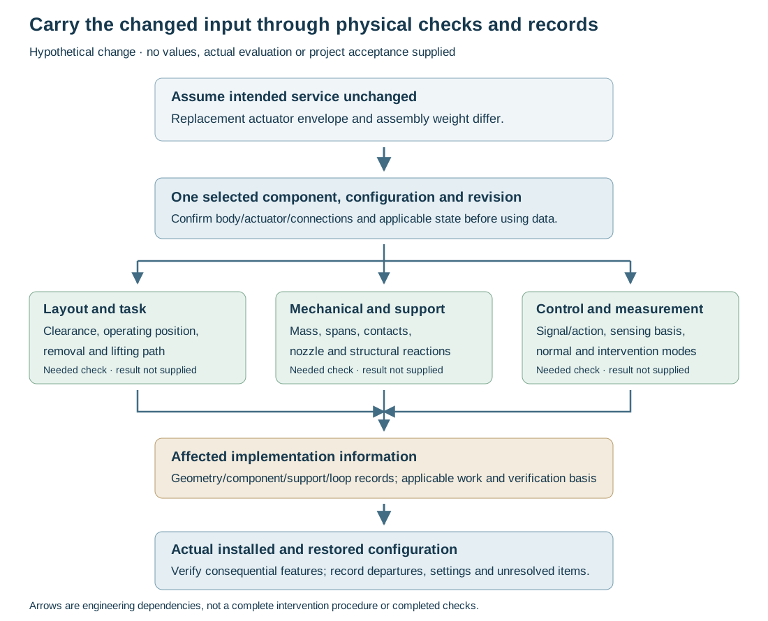
Figure 22.1. The assumed change in actuator envelope and assembly weight enters several evaluations and implementation records. The same selected identity/state must connect those outputs to actual installed verification. Arrows identify consequences and information dependencies, not a complete work procedure or an accepted plant modification. Structured record chain.
An as-built record preserves the installed arrangement needed for operation, inspection, maintenance and future change. Its value lies in the information it establishes. Routing, material, component and attachment details can matter to a later physical assessment. A stamp saying as-built without those relevant details cannot answer the engineering question.
A riser documentation example specifies the resulting routing, material/wall/coating, fittings and clamp details because operators need them for inspection and maintenance. That specific physical scope illustrates the broader purpose. Plant piping, buried systems and offshore/riser installations have different relevant conditions. The buried, pipeline and offshore boundaries should remain visible in the record. One drawing set should not be forced onto every case.
Record verification separately from the intended arrangement. A measured or observed field location, an inspection result, a test record and a restored operating configuration establish different facts. Identify their boundary, state and method. A pressure test does not prove that every instrument connection was restored, that a guide is free to slide or that a withdrawal path is usable.
Temporary arrangements need their own closure. Test blinds, spools, supports, locks, bypasses and isolated sensing paths can change the state. Document their selected removal or retention and the verified final condition. A spring setting called cold is meaningful only with its reference contents and equipment condition. Support states and restoration explain why the same coordinate or mark can mean different things before and after filling or testing.