Chapter 18 — Fabrication and construction of the installation
Spool boundaries, field joints, transport restraints and installation tolerances must preserve the intended geometry, material, containment and movement. A spool is a fabricated subassembly handled and installed as a unit; one line isometric can contain several. A module can include equipment, structure, piping and instruments. Transport and lifting are separate load states whose supports and restraints can differ from the operating arrangement.
Dividing work between shop and field
Shop fabrication offers a controlled work area, established equipment, qualified personnel and continuity of material supply. It can reduce exposure to weather and make examination, heat treatment and dimensional checking easier. A site weld bay can provide some of these advantages while avoiding long-distance transport. Field fabrication retains direct access to actual equipment locations and is useful for long straight runs, closing pieces and connections whose final dimensions cannot yet be established.
The division follows the work, material and installation conditions. Alloy or heat-treated piping may benefit substantially from controlled shop work. A large, uncomplicated straight run may gain little from being shipped as a completed spool. A compact assembly can contain too many attachments to transport safely, even though it fits within a vehicle's overall envelope.
Conversely, dividing that assembly too finely can multiply field welds and create examination or heat-treatment work in difficult locations. Size alone does not settle the choice. Nominal-size rules that assign shop and field work are requirements of the particular construction basis.
Choose spool boundaries with the available erection opening, lifting/support surfaces, final-joint and tool-withdrawal access, and any local heat-treatment envelope. A support or reinforcing pad over a joint can prevent required examination.
Modules extend the same argument. Their framing and lifting points carry the assembled weight during handling. Temporary supports may be needed for small-bore piping or instruments vulnerable to transport vibration. Guards and preservation protect delicate items and machinery.
These provisions should be identifiable so that the intended service configuration can be established after transport. A shipping brace left in place can restrain a movement that the operating design requires. Removing a brace before its intended handling duty is complete can leave an unsupported assembly. The relevant support states must be defined for both events.
Plan from usable lengths to joints and work access
Delivered pipe length is a fabrication input, not merely a purchasing description. Different manufacturing routes can supply different lengths. Machining of a thick cast or forged product can make shorter pieces practical. Shorter pieces can multiply butt welds along the same route. Their effect reaches preparation, weld production, examination, heat treatment where required, material loss, handling and access. A lower price per unit bare-pipe length therefore does not independently establish a lower installed cost.
Usable length excludes end-preparation, trim, damage and field-fit allowances. Longer pieces can reduce internal joints but increase surplus and handling difficulty; a required field division can add a joint. Each remaining joint needs preparation, examination and treatment access. Historical random-length purchasing categories do not guarantee a current usable length.
Describing the spool so it can be made and checked
The spool description connects terminal geometry and datums, component/cut-piece identity, shop/field joint locations, drawing revision and fabrication/examination/treatment requirements. A total pipe length does not identify the individual cut pieces.
A single-plane spool can often be shown clearly in an orthographic view. An isometric is useful when changes of direction occupy several planes, provided that dimensions and orientation are unambiguous. Neither drawing convention makes a dimension implicit. Flange faces, branch directions, elevations and the relationship to a plant datum must be specified. Nominal pipe size and schedule identify a product. They do not supply every actual takeout or bore needed to fabricate it.
Component takeout is the part of a specified assembly dimension occupied by the component, measured between the datums used on the drawing. For an elbow this may be a center-to-end dimension. For a flange connection it may involve a center-to-face dimension or another defined terminal. Using the wrong datum produces a wrong cut length even when the subtraction is arithmetically correct. Weld root gaps, socket insertion and flange/gasket relationships must likewise be represented by their actual assembly conventions. A dimension to a flange face cannot silently become a dimension to its welding end.
A separate dimensional check after fabrication compares the completed spool with the same datums. It should include dimensions that control installation, not only individual cut lengths. Heat treatment and welding can alter the completed geometry. Inspection of a loose pipe before those operations does not establish the final spool dimension.
Reading a weld symbol into a physical joint
A welding symbol identifies its physical joint, members and side through the arrow and the selected reference-line convention.
In the illustrated single-reference-line convention, a fillet or groove symbol below the reference line specifies the arrow side. One above specifies the other side. Symbols on both sides specify both. “Below” describes the symbol's place on the reference line. It does not mean the lower surface of the pipe or the underside of the spool. Reversing the direction of the arrow and tail does not reverse those reference-line meanings.

Figure 18.1. Selected single-reference-line teaching legend. The filled dot is the field-weld mark in this historical convention. Before interpreting a production instruction, establish the drawing's symbol standard and edition. The examples select notation, not a welding procedure. Structured legend and worked reading.
The physical interpretation depends on the joint. A butt joint has opposite faces of the joint. A tee or corner joint has different sides of the member intersection. A lap-joint arrow may identify a joint side or a particular member where the symbol requires it.
An edge joint similarly needs its members identified. For bevel and J preparations, identifying the member to be prepared matters. A line pointing generally toward an assembly may leave that instruction unresolved. Establish the arrow's member designation from the adopted legend and drawing detail before cutting.
A second fillet on the opposite side of a tee cannot be inferred from a single arrow-side triangle.
The symbol's fields answer different questions. A fillet size is its specified leg length in this selected convention. A groove preparation can specify chamfer depth, root opening and included groove angle. These are separate from weld size and any separately specified root penetration.
Weld length lies to the right of the basic symbol. In an intermittent-weld instruction, length–pitch gives the length of each increment and the center-to-center spacing of increments. Pitch is not the clear gap. A chain arrangement aligns opposite-side increments.
A staggered arrangement offsets them. Neither arrangement should be substituted merely because the total deposited length appears similar.
| Selected notation |
Reading operation |
Consequential distinction |
| Fillet triangle below / above / both sides of line |
Locate arrow-side / other-side / both physical deposits |
Drawing rotation does not change the symbol's reference-line side |
| Single-V groove with separate depth, opening and angle fields |
Identify preparation depth, root opening and included angle separately |
Preparation depth is not automatically penetration beyond the root |
| Length–pitch beside an intermittent fillet |
Read increment length and center-to-center pitch |
Subtracting length from pitch gives a clear interval only for equal straight increments in the stated arrangement |
| Open circle at arrow/reference-line junction |
Weld extends completely around the indicated joint |
This does not mean “all joints on this spool” |
| Filled dot in this selected historical legend |
Work is made at a place other than initial construction |
The dot must not silently acquire a flag's meaning from another legend |
| Flush or convex contour mark with a finish letter |
Read required contour and the method for attaining it |
A finish letter does not specify a numerical surface-finish degree |
| Tail reference |
Follow specified process, specification or detail |
An omitted tail does not create an unqualified freedom to choose a process |
The basic-symbol type still governs which locations are meaningful. The selected chart marks the both-side entries for plug/slot and arc-spot/arc-seam symbols “not used.” Surfacing and selected resistance symbols have entries with no arrow-side/other-side significance. These exceptions prevent extending the fillet above/below rule to every mark. Back or backing weld and melt-through symbols also describe different features. The selected legend does not dimension the melt-through symbol. Where several weld types are combined, read each applicable feature rather than treating the combined graphic as a single generic weld.
A length–pitch instruction does not establish the number of increments, opposite-side welding or terminal extent; those require their own drawing instructions. Resolve an inconsistent all-around/intermittent extent before fabrication.
After decoding the symbol, reconcile it with the spool geometry, joint detail, material and examination route. The notation tells the fabricator what is described. The procedure qualification and production control establish how the actual joint can be made and checked. A physically readable symbol can still describe a joint outside a selected procedure's qualified range. A qualified process cannot repair an ambiguous member or dimension designation on the spool sheet.
An offset calculation that keeps the datums visible
Two parallel line portions can be connected by a diagonal portion and two elbows. In a single-plane offset, H is the perpendicular separation of the parallel centerlines. The diagonal makes angle θ to either parallel centerline. The advance along the original direction is X. The diagonal distance between the two virtual centerline intersections is S. For 0° < θ < 90°,
H, X and S are lengths in the same units. The trigonometric function for angle θ is evaluated in the selected angle convention. The right triangle gives the centerline layout. It does not yet give the length of pipe to cut.
The actual elbow takeouts along the diagonal are e₁ and e₂. The specified butt-weld root gaps at the two ends of that straight piece are g₁ and g₂. Its required end-to-end length L is:
This equation applies to the geometry and datums just defined. Different end connections or drawing conventions require their own dimensional chain. A negative or implausibly short L warns that the proposed arrangement lacks room for its components and joint work. It is not an instruction to shorten the elbows.
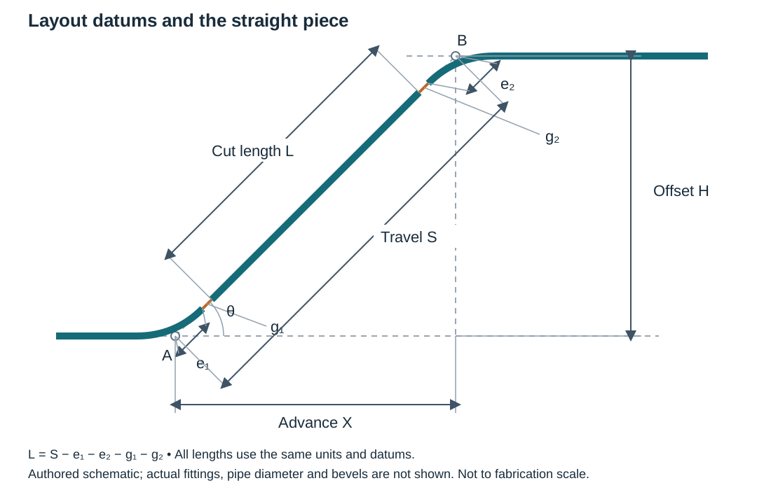
Figure 18.2. The figure is an authored, single-plane geometric example. Dashed virtual intersections define S. The solid straight piece occupies L. Pipe diameter, actual elbow form and weld preparation are omitted. The drawing is not to fabrication scale. Its structured dimensional method retains the defined datums and teaching calculation.
Cut length differs from centerline travel by the actual fitting takeouts and specified joint gaps. Production dimensions also require the actual preparation and fabrication tolerance basis.
A rolled offset adds a second perpendicular separation. If Hᵧ and H𝓏 are perpendicular offsets in two orthogonal directions, the resultant offset is H = √(Hᵧ² + H𝓏²). The same triangle then determines travel and advance in the plane of that resultant. A roll angle, such as φ = atan2(H𝓏, Hᵧ), locates the plane and preserves the signs of the two offsets.
All offsets must share a datum and units. Computing the resultant but omitting its orientation can produce the right travel length and the wrong spool. The completed elbow orientation requires stated axes and signs.
A nozzle cutback locates a different part of the dimensional chain
A branch nozzle has to meet the intended parent surface while leaving its terminal at the specified position. The centerline layout alone does not locate the nozzle's profiled end. A cutback supplies a scalar reference from the header centerline to the nozzle's nearest point under a defined contact convention. It is useful in determining nozzle-pipe length, but it must remain attached to that convention. Nominal branch size, nozzle outside diameter and nozzle inside diameter are different quantities.
The straight-header method considered here is a centered, 90° nozzle whose inside diameter rests on the header outside diameter. A construction that instead inserts the nozzle outside diameter into a parent bore or opening has different contact and preparation datums. Do not transfer this cutback unchanged merely because both arrangements are called a stub-in. The centered long-radius-elbow method below has a different reference: the virtual intersection of the elbow's tangent centerlines. It is not the curvature center or the straight header's cross-sectional center.
To establish nozzle-pipe length:
- First establish the intended construction, parent geometry, actual nozzle bore, terminal face and component takeouts.
- Then determine the cutback.
- Close the axial dimension using those same references.
The final end profile, bevel, root opening, retained wall, reinforcement and attachment qualification remain separate work in branch selection and joint preparation. A scalar cutback cannot generate the entire saddle or provide a weld-ready template around the nozzle circumference.
In the cross-section normal to a circular straight header, let be header outside diameter and nozzle inside diameter. The bore edges lie to either side of the centered nozzle axis. At their intersection with the upper header outside surface, the cutback satisfies
This is a right-triangle derivation of the depicted circular ID-to-OD contact. All quantities are lengths in one consistent unit. The radicand has squared-length units. Select the positive root for the upper-surface construction shown.
This point calculation does not include header ovality, an off-center branch, another angle or the nozzle wall/bevel profile. A nonnegative radicand is necessary for this intersection. If , the centered circular model has no real bore-edge contact. Another construction requires its own geometry.
A value for the missing intersection must not be invented.
Increasing the nozzle wall at fixed nozzle outside diameter reduces its bore and increases this geometric cutback. Header wall thickness does not appear in the equation because the contact is to its outside surface. It remains consequential to opening, reinforcement and welding. Neither effect should be inferred from nominal labels alone.
A useful historical dimensional comparison takes a nominal 6-inch header with 6.625-inch OD and a nominal 2-inch nozzle with 2.375-inch OD. The associated pipe-data basis lists a 0.154-inch standard wall and 2.067-inch bore, versus a 0.218-inch extra-strong wall and 1.939-inch bore. These are selected historical dimensions, not a present catalog or measured installed product. On those dimensions,
The selected standard-weight and extra-heavy cutback lookup entries are 3-1/8 and 3-3/16 inches respectively. Keep the lookup values and independently evaluated circle geometry distinguishable. Their increment and underlying fabrication conventions do not establish a universal rounding rule for every cell. They also do not establish that standard weight means Schedule 40 or extra heavy means Schedule 80 at every size.
Table 18.1. Selected raw lookup cases for the centered straight-header ID-to-OD method. Header sizes are the column designation and nozzle sizes the row designation. Structured values, dimensions and qualifications.
| Nozzle / header nominal sizes, in. |
Standard-weight entry, in. |
Extra-heavy entry, in. |
Meaning retained with the entry |
| 2 / 6 |
3-1/8 |
3-3/16 |
Selected populated comparison; actual bore and OD still govern the geometric calculation |
| 2 / 2 |
0 |
0 |
Literal zero in each lookup; not proof of zero circle-intersection cutback for actual dimensions |
| 3 / 2 |
Not supplied |
Not supplied |
Blank case, not a zero or an inferred fabrication permission |
The diagonal zero is a consequential qualification. Using 2.375-inch header OD and 2.067-inch nozzle ID gives inch, not zero. The lookup does not explain a construction convention that reconciles its printed zero with that circle calculation. Retain the zero as a raw lookup entry and resolve the applicable physical detail before using it as a dimensional-chain input.
Do not silently replace it with 0.58484 or erase the distinction. Likewise, the blank nozzle-3/header-2 case supplies no table value. With the selected standard 3-inch nozzle bore of 3.068 inches and a 2.375-inch header OD, the radicand is negative for this model. That mathematical result does not prohibit every larger-outlet construction.
It identifies why this particular centered ID-to-OD intersection cannot supply the missing value.

Figure 18.3. Authored circular contact geometry and a separate axial datum chain. The header OD and nozzle ID define . The nozzle outside-wall profile is omitted. The chain's terminal and takeout dimensions are hypothetical and are not drawn on the contact panel's scale. Structured geometry and checked calculations define the same references. This scalar reference is not a complete cutting template.
The centered long-radius-elbow construction
A curved parent changes the datum as well as the contour. In the depicted ideal 90° elbow, extend the two tangent centerlines to their virtual intersection . The curvature center lies one centerline radius away in both coordinate directions. The nozzle axis follows the horizontal tangent-centerline extension through .
Its lower bore edge is a distance below that axis. The outside bend circle has radius , and its bore-edge contact is horizontally from . The printed relationships for this construction are
Here is elbow outside diameter at the evaluated bend, and is nozzle inside diameter. The actual centerline bend radius is . The local lengths use the same units. is the vertical separation from curvature center to the lower bore edge.
is the signed horizontal contact coordinate from , positive toward the elbow's horizontal tangent end. These symbols belong to this elbow construction, not to the preceding offset triangle. A component center-to-end dimension that includes an additional straight tangent is not automatically its bend radius.
Use for the contact branch depicted on the left side of the curvature center. The negative square-root branch would locate another circle point. For this contact branch:
- Evaluate the radicand.
- Verify that the point lies on the actual 90° bend surface.
- Verify that both bore-edge locations and the nozzle wall/preparation fit the intended connection.
- Verify that the sign of agrees with the drawing.
An elbow's actual contour, straight ends, ovality or another branch location can invalidate the ideal circle even when the arithmetic has a real root.
For a worked geometric case, assume the selected 6.625-inch elbow OD, a 2.067-inch nozzle bore and an actual centerline radius of 9.000 inches. The radius is an explicit teaching input, not a dimension inferred solely from the words “long radius.” Then inches, inches and
The selected standard-weight elbow lookup for nozzle 2 / elbow 6 is 1-7/8 inches. It is a separate raw lookup beside this explicitly dimensioned calculation, not an identity claimed for every table entry or actual elbow.
The boundaries show why a real radicand is not sufficient. At , and the indicated lower-edge contact reaches the tangent-end boundary of the ideal quarter circle. That degeneracy does not establish a usable branch attachment. For a hypothetical , and inches, the radicand is positive but inch.
That real contact lies on the opposite side of from the positive- layout. Taking its absolute value would move the endpoint. Re-establish the actual datum and eligible physical detail before carrying such a signed result into a cut length. If the nozzle bore exceeds the elbow OD in this construction, the radicand becomes negative and provides no real contact.
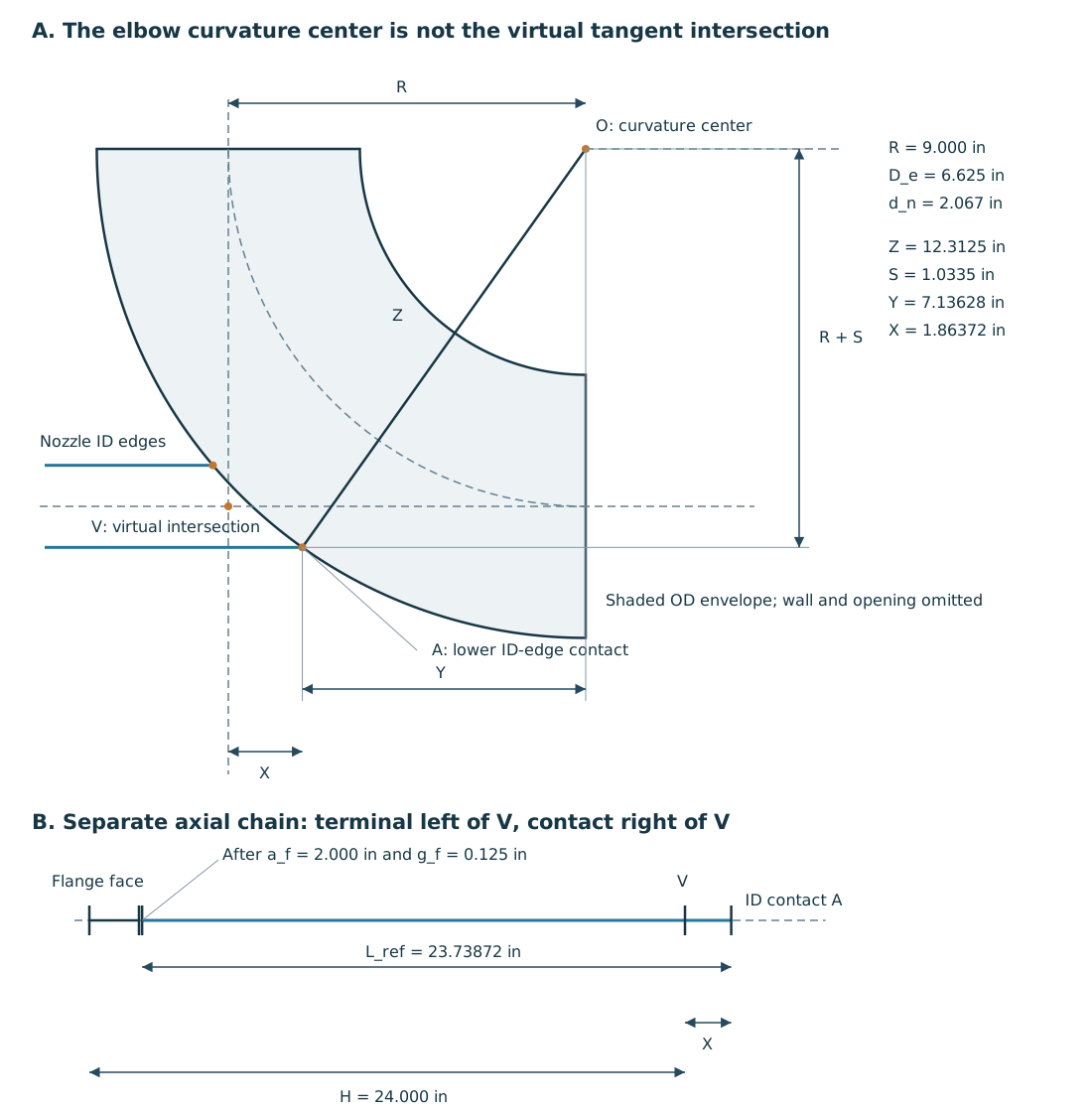
Figure 18.4. Authored ideal 90° elbow geometry. The curvature center , virtual tangent intersection , lower bore-edge contact and tangent end are distinct references. The positive branch and are shown. A separate chain panel locates a hypothetical flange face to the left of . It does not put that face in the contact panel at a fabricated distance. Structured points, quantities and cases accompany the figure.
Actual end profile, wall and qualified attachment are not supplied.
Close the nozzle length using the selected reference
The sign of a subtraction follows the physical datum chain. For the straight-header example, put the flange terminal face a perpendicular distance above the header centerline. Let be its face-to-nozzle-welding-end takeout and the specified flange-to-nozzle butt-weld root gap. If the nozzle's reference length is measured from that butt end to the bore-edge intersection used for ,
Assume hypothetical , and inches. The actual-dimension circle result for the standard bore gives inches. The heavier bore gives 18.70755 inches. Using the separate selected lookup values would instead give 18.75000 and 18.68750 inches.
These computations retain which cutback basis produced the dimension. They do not justify choosing the shorter answer or issuing five-decimal shop dimensions. The applicable physical detail, product dimensions, drawing convention and fabrication precision must establish the production value.
For the elbow example, place the hypothetical flange face inches to the left of . The contact is inches to its right. With the same hypothetical and ,
This is a plus sign because the defined contact lies beyond the virtual intersection from the terminal. Subtracting as though it were the straight-header would give 20.01128 inches and locate another end. The separate elbow lookup value 1-7/8 inches would give 23.75000 inches on its own basis. Neither the curvature-center radius nor the elbow takeout can be substituted for .
These are nozzle lengths on the stated bore-edge reference, not an automatic full-wall blank or weld-ready profile. A drawing may define a different long-point, short-point or stock-cut convention. Preserve the relation from this reference to its actual profiled end, joint preparation and trimming allowance rather than inventing those unprovided dimensions. The flange root gap used here is a specified teaching input at one named joint. It is not a general branch-mouth gap.
Actual diameters/radius, the selected ID-to-OD construction, any lookup row/column, signed takeouts and available preparation access govern the cut instruction.
After forming and joining, evaluate the completed terminal-to-parent relationship on those same datums.
A closed scalar chain can still have the wrong branch orientation, a damaged bore or an unqualified opening. The useful output is a traceable dimensional instruction that can be made and checked, connected to the separately established branch and welding basis.
Tolerances, field fit and equipment connections
A fabrication tolerance bounds departure from a specified dimension. It does not change the nominal design dimension and does not authorize any stress produced by forcing the completed parts together. Tolerances on a spool, equipment setting and structural construction can accumulate at a closing connection. The accumulated discrepancy has translation and orientation: a line can meet the nozzle position but approach it at the wrong angle.
As an example of a bounded dimensional specification, the following limits apply when a fabrication basis adopts this particular length-tolerance schedule. They are not default tolerances for every piping system.
Table 18.2. Conditional spool length-tolerance schedule, retained in the structured fabrication tables.
| Controlled dimension |
Specified length < 1.5 m |
Specified length ≥ 1.5 m |
| Distance between two parallel or crossing centerlines |
±1.5 mm |
±3 mm |
| Centerline to flange face |
±1.5 mm |
±3 mm |
| Flange face to flange face |
±1.5 mm |
±3 mm |
The boundary at 1.5 m belongs to the larger-length category in this schedule. Flange-face alignment has separate criteria. The length table does not supply angular or lateral alignment limits. Other specifications use their own dimensional and alignment bases, and their values should be carried into the work package rather than mixed with this example.
Terminal tolerances can oppose and accumulate at closure; angular errors and the closing spool's own error are additional inputs. Tolerance accumulation does not establish permissible flange pull-up or equipment load, and statistical cancellation requires its own population/dependence basis.
A planned field-fit length provides material that can be measured and trimmed after the neighboring equipment and spools have reached their actual positions. A closing piece can then be prepared and joined without making the equipment nozzle absorb the dimensional discrepancy. The field joint needs sufficient straight length and access for cutting, beveling, fit-up, welding and examination. It also requires a defined test route. A fitting-to-fitting connection can remove all of this useful adjustment space. Including a suitable spool length in a pump suction or air-cooler connection is therefore a constructibility decision with mechanical consequences, not simply a drafting convenience.
Before closure, compare actual terminal location, flange face orientation, bolt-hole orientation, pipe/support position and any specified installation preset. Correct the cause of a mismatch within an accepted fabrication or engineering method. Cutting and remaking a piece may be preferable to retaining a strained fit. Heating or forcing a completed spool changes its material and mechanical history.
It needs a procedure suitable for the material, service and previous treatment. The alternatives differ in cost, reexamination and treatment work. A flange tightened until it appears aligned has concealed the discrepancy rather than demonstrated its acceptability.
Designed cold spring is a separate matter. It is an intentional installed displacement with a defined method and evaluation, addressed with flexibility and equipment loads. Random construction pull-up must not be renamed cold spring. Likewise, a pipe that is flexible enough to move into position may still transfer a consequential force or moment to a machine. The installation check preserves the actual conditions assumed in the mechanical evaluation.
Select a correction that preserves the material and installed result
Cutting and remaking a spool exchanges additional joint work for an unstrained fit. Heating or forcing it exchanges that work for another material and mechanical history. A heater-coil procedure ranks cutting/rewelding first, local non-uniform heating or cooling second, and force with heating third. The procedure requires the correction method to be established before work. Rewelding reopens the joint's qualification, examination and treatment. A heated correction requires its own temperature measurement, cooling and any renewed properties or PWHT.
For a particular carbon-steel route without required PWHT, the heated-correction maximum is 600°C with still-air cooling. Its temperature-crayon method reserves a 50°C margin, so the indicated maximum is 550°C. Carbon steel that requires PWHT instead retains its treatment maximum and either a compliant thermal cycle or renewed treatment of the corrected region, without quenching. The Cr-Mo route adds hardness checks on the heated/forced area under its defined criterion. These are scoped correction conditions, not temperatures at which ordinary installation pull-up becomes acceptable. The structured correction comparison retains the distinctions.
The stainless variants demonstrate why selecting a stricter number is insufficient. The heater-coil route permits necessary force with brief heating limited to 500°C. A separate general spool route limits heating to 650°C and prohibits force for austenitic stainless. Each uses its specified measurement margin and complete material/work basis. Combining the coil temperature with the general route's force rule would create a third procedure with no supplied warrant. After cooling, the selected method requires renewed terminal/face/support checks and affected treatment/examination. The equipment connection must not retain a hidden strain.
Keeping material identity through manufacture
Material identity must survive cutting, assembly and installation so the actual grade, wall, heat-treatment and impact-test condition remain attached to the installed item. A physical marking must match its certificate and specified product.
Color coding can help personnel distinguish material groups quickly, but it supplements the specified markings and records. A color is not a material certificate. Schemes also differ between projects. Marking materials must be compatible with the substrate and service. Do not cover the information needed to identify the product or contaminate weld bevels, threads, internal surfaces or gasket seating faces. A replacement piece that looks identical can differ in grade, wall, heat treatment or impact-test condition.
The procurement/construction basis determines certificate, marking and examination requirements. Some complete controlled-traceability routes permit reduced later alloy identification; others require PMI in addition. Lost identity needs its specified recovery route.
Positive material identification answers a material-composition question within the capability of the selected method. It does not by itself establish every required mechanical property, original heat treatment or certification relationship. Traceability, PMI, dimensional inspection and weld examination therefore remain complementary. Their detailed material and examination roles are developed in materials and procurement and welding and examination.
A proposed substitution should state the original requirement, the proposed product and the resulting differences. A change in wall thickness may alter fitting alignment and weight as well as pressure capacity. A change in grade may alter welding, heat treatment and corrosion behavior. The accepted disposition must reach the drawings, material list and procedures before the changed item is incorporated. Recording only the supplier's replacement part number leaves these interfaces unresolved.
Carry the heat lot and component population through verification
A material-identity check must preserve which items its result represents. One fabrication procedure performs the 300-series stainless component analyses on completed spools before any required PWHT. Component selection is distributed evenly among the completed spools. It uses at least 10% of each fitting type per heat lot and 10% of each flange type per heat lot.
It separately analyzes straight pipe on at least 10% of completed spools for each pipe diameter. Fittings and flanges without identifiable heat lots receive 100% analysis under that method. Other listed alloys have their own 100% component scope. These are identity populations, not the percentage of welds required for radiography or hardness testing.
Each fitting/flange type and heat lot is a separate sampling population. Missing heat-lot identity invokes the specified 100% scope rather than increasing an identified lot's denominator. The structured PMI companion retains scoped populations and hypothetical arithmetic.
The selected analyzer must resolve the required alloy elements. If it cannot identify a component, an accepted laboratory route can be necessary, with sample removal and traceability preserving both identity and remaining wall. In the specified response, a measured major alloy element below its required range rejects the respective heat lot unless the permitted wet-chemistry check determines its disposition. Rejected components without lot identity expand analysis to similar unidentified components. A higher-than-specified measured alloy concentration is referred for its own acceptance disposition. “More alloy” is not automatically equivalent to the ordered material.
Another fabrication basis instead permits omission of post-assembly alloy identification when its complete auditable chain of procurement marking/certificates, receipt matching, grade-segregated storage, controlled issue and maintained fabrication segregation is followed. Failure of any stage invokes completed-item PMI under that basis. A heater-coil procedure independently calls for alloy-element verification of materials and weld deposits after fabrication. These are different complete identity routes. A complete certificate file does not waive a specified sampling requirement in the first. A spot analysis does not recreate a lost heat-to-installed-item relationship in the second.
Make the correct reassembly physically recognizable
Repeated removable spools can have similar configurations but different metallurgy. An adopted arrangement can give them different shapes or lengths. A lower-alloy item then cannot readily occupy the higher-alloy location. This physical prevention complements material marking and the restored-item check. A shape alone does not certify composition or condition. Keep the differentiating geometry in the fabrication detail rather than leave interchange prevention to a temporary tag that can be lost.
An injection quill adds orientation to that identity question. Under a specified concurrent-flow route, the detail identifies bulk-flow direction with an arrow and a secondary positive reference such as a coordinate or downstream equipment item. The quill's opening points in that same direction. One-way installation geometry, or matching downstream alignment tabs/pins on the quill and mating flange, makes the intended orientation physically recognizable.
That route retains its injection/mixing and downstream-erosion assessment. Keying does not authorize concurrent flow for every process. The structured reassembly-prevention examples retain the two different functions.
The detail and P&ID must preserve the quill's positive reference, keying, material and discharge orientation through withdrawal/replacement. Changed mating parts reopen that check. See change records.
Preparing and assembling the joints
Cutting and beveling establish the joint geometry and expose the surface that will be joined. Mechanical, thermal, plasma and water cutting have different material applicability and finishing requirements. Thermal cuts can leave oxides or an affected surface that must be removed under the specified preparation procedure. Stainless steel preparation also requires control of contamination and dedicated tools where prescribed. An allowance left for field cutting is useful only if the final cut can be prepared correctly at site. A shop-prepared bevel may have to be removed when that allowance is trimmed.
Butt-weld fit-up controls root gap, bore alignment and the relationship between unequal wall or bore dimensions. A permitted taper or transition must preserve the minimum required wall, including applicable allowances. Grinding until two bores appear flush is not a sufficient dimensional criterion. The joint preparation and production welding route are established in the welding procedure. This chapter carries them into the sequence, space and actual dimensions of the assembly.
Socket joints illustrate why appearance alone is inadequate. A square, deburred end enters a socket, but a specified clearance is retained between the pipe end and the socket stop before welding. The clearance avoids the adverse shrinkage/restraint condition associated with a pipe bottomed hard against the stop. Insertion and clearance are separate dimensions. A satisfactory external fillet does not show that the internal fit-up was correct. The specified gap, insertion and verification method must therefore be established before concealment.
Threaded joints require the intended thread form, engagement and condition. Where a specified joint is to be seal welded, the adopted procedure determines preparation and excludes incompatible sealant or lubricant from that weld. Seal welding is not a general remedy for every threaded connection. Welding or heat treatment can also affect threads. The fabrication procedure may require checking or chasing them afterward. Thermowell and other insert openings must remain unobstructed.
At flanges, face orientation and bolt-hole orientation are independent checks. A face can be perpendicular to its pipe axis but rotated incorrectly relative to the mating flange. The specified gasket, bolting, lubricant and tightening method then establish the joint assembly. Their detailed selection belongs in pressure-retaining joints. Use of a long stud, a different lubricant or additional washers can alter the actual assembly even when the flange rating is unchanged. Bolting must not become a tool for absorbing an unreviewed piping mismatch.
Branch and attachment sequence affects examination access. A branch root may need internal examination before its next component is fitted. A reinforcing pad may need to follow examination of the pressure-containing weld but precede required heat treatment. Support shoes and other attachments on a line requiring PWHT need locations and welding sequence compatible with that treatment.
Source specifications differ on longitudinal seam orientation, weld spacing and attachment location. The fabrication drawing should carry the selected basis explicitly. A generic preference such as “keep welds away from supports” cannot replace its actual conditions or exceptions.
Valves add an internal assembly that fabrication can damage. Welding heat can impair soft seats or distort bodies. Flushing debris can score seating surfaces. Manufacturer instructions, the specified valve condition during welding and the sequence of flushing or temporary-spool use therefore belong in the work package.
A check valve needs the correct flow orientation, and any shipping restraint on its disc must be removed at the intended stage. A butterfly valve needs mating bore clearance and a suitable installation position so that its disc and resilient facing are not damaged or jammed. Completing a mechanical operating check after installation verifies a function that an external dimensional check cannot establish.
Sealing threads and bridging a short branch root
A short threaded branch root concentrates several interfaces into little space. These include the run-to-branch fitting attachment, nipple or valve male end, engaged threads and valve body. The weld placed at a threaded joint must therefore be described by its actual purpose and coverage. A seal weld can close the leakage path and cover exposed thread notches. It does not automatically turn a threaded assembly into a qualified full-strength welded joint. The thread engagement remains a distinct fit-up condition, and the run-to-fitting attachment remains a separate weld.

Figure 18.5. Conceptual sections for a selected short branch-root detail. Hatched gray is component material. Blue is the selected deposited weld. Internal engagement is shown separately from the exterior coverage. The two bridge alternatives preserve the short nipple and integral male-ended valve arrangements. Structured geometry and conditions.
In the selected seal-weld detail, the weld covers all exposed threads, including thread-runout scratches, and covers the entire fitting face at the joint. It blends smoothly into the pipe without undercut. The depicted sealing profile is flat or slightly concave rather than convex. These coverage and contour instructions address the local thread/runout geometry.
A small bead that leaves the last thread scratch uncovered has not achieved that detail, even if a subsequent leak test finds no leakage. The selected assembly is made up dry, without thread compound or PTFE tape, and with proper thread engagement before welding. Establish these conditions before the weld conceals them.
The bridge detail addresses the region between the branch fitting and the valve hub in severe cyclic service. Its two physical alternatives are a short nipple with a socket-welding or threaded valve, and a valve with a male end. In the nipple alternative the selected seal-weld buildup extends to the full valve-hub diameter for the full nipple length. This is additional deposited geometry spanning the short root region, rather than two isolated sealing beads at its ends.
The male-ended alternative removes the separate nipple but retains a defined bridge between fitting and valve. The run attachment shown with these alternatives is on a 2 in or larger line. That depicted condition does not establish a general permission for every run size or branch fitting.
The accompanying short-nipple detail has a local bridging instruction. It applies where the remaining spacing shown between the separate seal-weld regions is less than 1/4 in, to avoid a notch effect. That spacing is not the nipple's full length L between its engaged ends. Keep both dimensions identifiable: “make the nipple as short as practical” must not leave an unexamined narrow groove between adjacent beads. The 1/4 in condition belongs to this selected detail and its geometry, rather than a universal bridge-welding threshold. A fabrication drawing using it needs to identify the intended fitting, nipple, valve end and weld boundaries so that its local spacing can actually be checked.
Bridging changes the exterior section and the way local loads pass through it. Its presence does not establish a fatigue rating or a pressure-strength calculation. Material, wall, engagement, fitting/valve construction, cyclic loading and the qualified welding route still govern adoption. The selected detail cannot be applied by adding weld metal to any short threaded nipple. Heat input and any required heat treatment must also be compatible with the valve internals and the selected preparation route. Valve thermal state and reassembly develops that interface; small-bore branch integrity connects the root to its support and vibration environment.
Thread engagement/cleanliness must be established before concealment; actual thread-runout enclosure, contour, undercut and bridge extent/hub transition are examined afterward. Pressure and functional tests do not recover an unobserved internal fit-up dimension. See production control and weld-symbol interpretation.
Treat the valve as an assembly during welding and PWHT
The required weld thermal cycle and the valve's internal heat tolerance must be achieved together. Seat distortion, damaged soft seats, packing or gaskets can leave a valve that is pressure-connected but cannot perform its shutoff function. Valve-body temperature, weld-region temperature and bonnet temperature are different observations. A heater setting or one favorable weld reading does not establish that the protected parts remained suitable.
Under a particular small carbon-steel valve procedure, socket/seal-weld work on P-1 valves through NPS 1½ is followed by its defined local treatment arrangement. Both welds are heated simultaneously, while the body and adjoining pipe are insulated and the upper bonnet is kept uninsulated and away from directly applied heat. The arrangement identifies weld/body preheat and interpass locations and a separate bonnet interpass location, with external thermocouples for treatment. Its valve position during PWHT—closed then backed off two handwheel turns—and its means of limiting convection belong to that particular valve/treatment method, not to every valve being welded.
A different class-specific PWHT preparation requires bolted bonnets/covers so that the bonnet or cover, gasket, internals and trim can be removed and tagged before stress relief. Restore the correct identified assembly with new gaskets after the required treatment and examination. The temporary body configuration must remain identifiable. Loose trim from a similar valve is not a verified substitute. This method does not prescribe an oven temperature or authorize dismantling another valve design.
A separate, specific soft-seat socket-valve procedure permits welding without disassembly for its specified construction in ¾-, 1- and 1½-in sizes. It uses its permitted arc processes and rod size, cools the body to 200°F between passes, and calls for prompt cooling after the last pass. A body reading above 400°F immediately after a pass triggers disassembly and visual examination for seat damage, with replacement if damaged. That scoped protection method is different from simply applying the small P-1 PWHT arrangement or removing internals under the class-specific preparation above.
Table 18.3. Assembly states and thermal questions, with structured route conditions.
| Bounded route |
Temporary state or protection |
Evidence needed for the next state |
| Specified small P-1 socket/seal valve welding and local PWHT |
Defined joint/body heating and insulation; bonnet protection; prescribed treatment position |
Actual measurement locations, completed thermal cycle, required examinations and functional condition |
| Class-specific valve preparation where PWHT is required |
Bolted bonnet/cover and vulnerable parts removed, tagged and protected |
Correct parts restored, new gaskets, required joint/assembly checks and test disposition |
| Specified soft-seat socket-valve welding without disassembly |
Model-qualified controlled passes and body cooling; overheat response |
Body-temperature observations, condition after an overheat event, reassembly/packing and operating checks |
The work package selects a complete route from the actual valve construction, material, seals, joining method and treatment duty. Other adopted soft-seat routes use an open closure member during welding. A gate/globe seating-protection route can instead require closed then half a turn open. Neither position instruction supplies the other's thermal or disassembly permission. After restoration, check orientation, complete operating travel, packing/gasket condition and the required containment evidence. A valve that cycles freely still needs its prescribed pressure boundary verification, while a leak-free body alone does not establish seat performance.
Locate the observations before applying the thermal cycle
The selected small P-1 valve method becomes more intelligible when its observation points and treatment envelope are drawn separately. The first panel identifies three locations on the valve assembly: bonnet interpass, body-joint preheat and interpass, and body preheat and interpass. Here body joint names the region at the bonnet/body connection. It is not a label for the pipe-to-valve socket weld. A reading at that connection addresses a different part of the assembly from a reading at the lower body or a weld-region thermocouple during treatment. Record which location produced each observation so that an acceptable body temperature cannot be mistaken for an acceptable bonnet condition.

Figure 18.6. Selected procedure for socket/seal welding of carbon-steel P-1 valves through NPS 1½. Observation geometry at left and treatment geometry at right are different stages of the same bounded route. The upper bonnet is uninsulated and receives no directly applied heat. Heat conducted from the body remains possible. Structured observation and arrangement data.
This selected SMAW route retains a 1/16 in minimum socket gap during tacking, filler of the same analysis as the base material and its preferred low-hydrogen electrode with maximum 0.05% carbon. Its specified preheat/interpass range applies to pipe and valve body under the adopted B31.3/welding basis. The location diagram supplies no missing temperature setpoint.
During local PWHT, both welds are heated simultaneously by the selected electrical-resistance or halogen-quartz route. The treatment thermocouple/external observation locations are associated with the heated joint regions. Insulation covers the body, welds and adjoining pipe while leaving the upper bonnet exposed. For the electrical-coil arrangement, the selected insulation extends at least 6 in along the pipe on each side of the valve to provide a gradual temperature gradient.
The halogen-quartz alternative requires its special application arrangement. It must not simply inherit every coil placement from the drawing. Heating rate, cooling rate and treatment temperature follow the adopted requirements, with a selected ½ hour hold at temperature.
The insulation-thickness statement in this historical route gives at least 1 in, paired in its text with 24.4 mm. Those printed units do not agree. The conversion of 1 in is 25.4 mm. When recovering the route, retain that discrepancy.
Before specifying or purchasing insulation, resolve the adopted thickness in the work package. The figure therefore identifies an insulation envelope and its selected inch condition, without silently treating 24.4 mm as an equivalent or choosing an undocumented substitute. The insulation material likewise needs the selected approval basis, not merely a similar appearance.
The thermal arrangement includes the valve's mechanical state. In this route the valve is closed completely and then backed off two full handwheel revolutions during PWHT. Short open pipe ends are sealed where required to prevent convection heat loss. These provisions are coupled to this valve/treatment method, rather than instructions to apply to another design.
An upper bonnet that is uninsulated and free of directly applied heat may still warm by conduction. Its separate observation matters. A coil controller or a good weld-temperature trace alone does not establish the packing, gasket or valve assembly condition.
The assembled-valve route does not inherit removed-internals or soft-seat-cooling permissions. Its two-turn PWHT position does not apply to those routes. Location-specific thermal evidence, final examination and restored operating/containment checks remain required; see thermal controls and hardness locations.
Bends and fabricated changes of direction
A pipe bend makes a change of direction within a length of pipe. A welded elbow introduces a manufactured component and its joining work. A mitered change of direction uses oblique cut-and-weld segments. These alternatives occupy different space and create different fabrication, inspection, flow and mechanical conditions. Where large-size fittings are unavailable or a particular radius is useful, a fabricated alternative may be practical. Geometry alone does not establish pressure or fatigue suitability.
A larger bend radius consumes more space. A tighter bend subjects the material to greater deformation. Bending can change wall thickness and cross-sectional shape and can produce wrinkles or cracks. The finished bend must therefore be evaluated for remaining wall, ovality or flattening, surface condition, dimensions and material properties. If the line is to be pigged, its bore and radius must also permit the required passage. The original pipe schedule does not demonstrate the minimum wall remaining after bending.
Cold bending, hot bending and induction bending have distinct process histories. Cold forming introduces deformation without the hot-forming temperature cycle. Hot forming requires controlled heating and cooling. In induction bending, a narrow circumferential band is heated while neighboring pipe supplies support as the bend advances. The forming speed, heated-band width, temperature measurement and cooling conditions become production variables. A qualified induction-bending program connects those variables with tested bends; production dimensional and material checks establish whether the delivered items remain within that basis.
The material and service boundaries matter. A carbon-steel bend, a quenched-and-tempered low-alloy bend and a duplex stainless-steel bend cannot inherit one heat-treatment rule from their common shape. The applicable procedure considers their original condition and the change caused by forming. Some fabrication specifications prescribe five-diameter or six-diameter minimum radii, while another provides selected radii and more detailed material/process conditions. Choosing the largest number across those practices would still fail to determine process qualification, remaining wall or service applicability. A prohibited field hot-bending operation likewise cannot be made acceptable merely by using a generous radius.
For a prescribed bend acceptance schedule, measurements of thinning, flattening and wrinkles are made against that schedule and the applicable pressure-design wall requirement. The definition of a wrinkle matters: a crest-to-valley height and its wavelength are not interchangeable with an overall diameter measurement. Cracks require their own disposition. An unacceptable crack must not be hidden by a cosmetic weld repair. The geometry and material examinations are distinct from the later test of the assembled line.
The spool detail also has to distinguish straight tangents from the curved portion. For an ideal circular centerline bend, the arc length is Rθ, where R is centerline radius and θ is the change of direction in radians. This is a geometric length, not a universal blank-cut instruction. The bending process, straight tangents, trimming allowance and actual finished dimensions still determine the required stock. Bend tables are useful only with their accompanying radius, angle and dimension diagram. A number taken from a table without its geometric letter or units can describe a different part of the bend.
Mitered elbows require similar discipline. Their joint count and angles affect flow disturbance and fabrication work. Fewer segments may reduce first cost while making a more abrupt change of direction. Their allowed pressure/service, wall and examination conditions must come from the selected design and fabrication basis. A table of miter cut dimensions teaches how to lay out a permitted configuration. It is not permission to replace any standard elbow with a miter.
Subdivide the turn, then locate the miter cuts
A segmented miter changes direction at its joints. Its layout begins with four inputs. These are required total turn Θ, number of miter joints m, actual pipe outside diameter d, and selected centerline layout radius R. Here R locates the circular construction used to lay out the tangent segments. The finished centerline is a polygon, not a smooth arc. The layout-circle, segment-axis, projected-terminal and inside/outside-edge references are distinct.

Figure 18.7. Selected planar equal-turn layouts and projected cut-plane references. The total turn, direction change at a joint and inclination of each cut from a square end are distinct angles. These are geometric layouts for an already permitted configuration, not developed-shell cutting templates or pressure/fatigue acceptance. Structured method, exact teaching row and calculations.
For equal direction changes, each joint turns the adjacent pipe axes through δ = Θ/m. Each mating cut plane bisects that change, giving α = δ/2 = Θ/(2m) as its inclination away from a square end. Thus a single-joint 30°, 45° or 60° turn has cuts inclined by 15°, 22½° or 30°, respectively. For a 90° assembly with two, three or four joints, the axes change by 45°, 30° or 22½° at each joint.
Each end cut is inclined by 22½°, 15° or 11¼°, respectively. There are m + 1 pieces. Calling a four-joint assembly “four pieces,” or cutting each end at the full direction-change angle, produces a different assembly.
In the projected circular construction, the first and last radial sectors are half sectors, with full sectors between them. A 90° two-joint layout therefore has sectors 22½° + 45° + 22½°. A three-joint layout has 15° + 30° + 30° + 15°. A four-joint layout has 11¼° + 22½° + 22½° + 22½° + 11¼°.
Those sector angles locate tangency points and cut intersections. They must not be added a second time as extra pipe-axis turns. Terminal faces in this construction are square to their terminal axes and located at the first/last tangency points. Additional straight tangents require their own dimensions.
Let r = d/2 and a = r tan α. For a cut through a straight circular pipe, a is an axial setback in the plane of the turn. It extends from the cut's centerline intersection to an extreme outside-surface edge. The long-to-short difference of one oblique end is 2a = d tan α.
This uses outside diameter, not nominal size, inside diameter or wall thickness. For an interior piece bounded by two symmetric cuts, let ℓc be its axial centerline length between those cut-plane intersections. The outer and inner extreme axial lengths are then:
ℓouter = ℓc + 2a; ℓinner = ℓc − 2a.
The construction radius gives ℓc = 2R tan α for a full interior tangent segment. Each unextended terminal segment has centerline length R tan α. For a terminal piece with one square end and one oblique end, the corresponding extremes differ from its centerline length by only a, not 2a. This distinction prevents applying an interior-piece allowance to an end piece. All lengths are axial or projected distances between the named planes, rather than lengths measured along an oblique edge or around the circumference.
| Selected historical layout references |
Meaning in its own drawing |
Use boundary |
| Single-joint 30°/45°/60° columns |
Axial half-setback between cut centerline and extreme edge for that total turn |
Select total turn first; do not read the column angle as each cut's inclination |
| Two-joint 90° layout A |
Half-setback at the selected 22½° cut |
An end-cut reference, not a centerline segment length |
| Two-joint 90° layout D / E / F |
Outer / centerline / inner axial lengths of the middle piece |
D and F bound the same selected piece; their mean can check E |
| Two-joint layout B / C |
Separate projected terminal reference intervals shown at the end of that layout |
Retain their actual terminal lines; do not substitute a middle-piece length |
| Three-joint layout G / H / I and J / K / L |
Its own end references and outer / centerline / inner interior-piece lengths |
G–L belong to the 15° cut configuration |
| Four-joint layout M / N / P and S / T / U |
Its own end references and outer / centerline / inner interior-piece lengths |
M–U belong to the 11¼° cut configuration |
A table lookup must bind the configuration, size or actual diameter basis, radius, units and dimension letter together. The historical two-joint table prints Size and R. Its companion three/four-joint table prints dimension letters but does not print Size or R row labels. Row position alone is insufficient authority to attach a nominal size/radius to a companion value. The geometric relations above can support an independently defined layout. They do not certify an undocumented row join or turn every historical rounded dimension into an exact trigonometric result.
For a selected table-based dimensional closure, use the explicitly labeled Size 6 row of the two-joint 90° layout. Its R is 9 in, and A is 1⅜ in. The middle-piece lengths are D = 10 3/16 in, E = 7 7/16 in, F = 4 11/16 in. The row's diagram and fractional dimensions are the example inputs, not a newly selected production spool. With these fractions:
(D + F)/2 = (10.1875 + 4.6875)/2 = 7.4375 in = E;
D − E = E − F = 2.75 in = 2A.
The outer-to-inner difference is 5.5 in = 4A. This checks that the three cut-length references describe the same symmetric middle piece. Independently, the ideal centerline construction gives 2 × 9 × tan 22½° = 7.455844 in, about 0.018344 in greater than the tabulated E. That small difference is retained as a difference between ideal geometry and the printed fractional table, not silently corrected or declared a fabrication tolerance. The row does not print actual outside diameter, so this example does not infer d from nominal Size 6 or calculate an undocumented outside-diameter allowance.
These lengths locate ideal cut planes. Stock cutting still needs the actual bevel/root-face preparation, fit-up gap, cutting kerf and trimming method, and the chosen finished dimensional datum. A kerf is material removed by the cutting operation. It is not a universal amount to add to every long-point dimension.
Reusing complementary cuts, reversing a piece and rotating it about its axis can change which marked edges meet. Keep the turn plane, inside/outside marks and piece sequence visible through fit-up. A reversed asymmetric piece or an unplanned axial rotation can introduce a different orientation even if individual long-point measurements agree.
Completed fit-up must preserve total axis turn, piece count, cut inclination, inner/outer orientation, terminal positions and actual root preparation, remaining wall, weld spacing and access. Spool datums, weld symbols and production control carry the layout into a qualified joining route. Material/wall, examination, allowed pressure/service and cyclic/vibration suitability remain separate: geometric closure does not permit replacing a manufactured elbow.
The bend's geometric observations remain separate from its pressure-design wall and material condition. One acceptance basis limits a wrinkle's vertical height from the average elevation of two adjoining crests to the intervening valley. It requires gradual blending of the wave shape, , and crest spacing relative to that height of , where is the nominal pipe-size length under that basis. All lengths use consistent units. These two inequalities describe different aspects of a wrinkle. They do not define overall ovality or permit a crack.
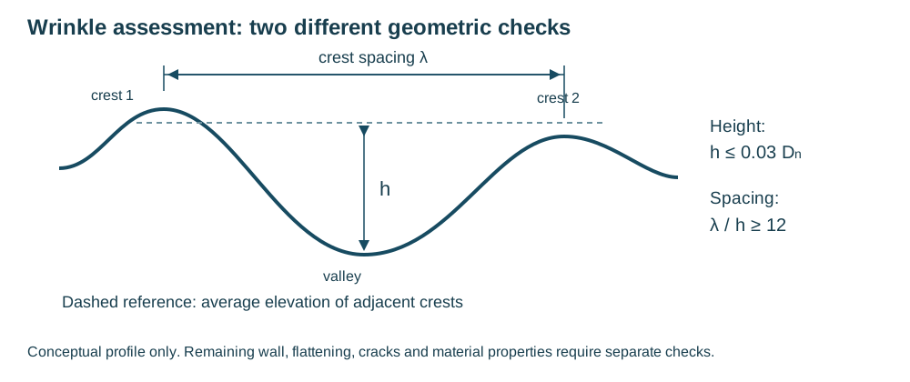
Figure 18.8. Authored measurement geometry for the stated wrinkle method, with structured geometry, conditions and hypothetical checks. Unequal crest elevations use their average as the height reference. This profile is not a manufactured bend or a permitted forming setup.
Wrinkle-height and crest-spacing conditions must both be satisfied. Remaining wall, flattening, cracks, dimensional fit and properties have separate criteria; the nominal-size length in this wrinkle method is not outside diameter in a strain formula.
An induction-bending qualification likewise does not replace production observations. One route qualifies at least two bends per material type at the smallest and largest diameter/wall combinations. Low-alloy work adds its stated heat-specific test bends and microstructure examination. Test bends cannot be repaired by welding.
For production, every bend receives its dimensional and visual checks after forming and heat treatment. One bend of each defined production run receives the specified wall, surface and hardness examinations. A run retains the same size, wall, material and controlled bending parameters. A changed setup cannot quietly remain inside the old representative population.
Under that production method, wall measurements cover complete inner and outer radii and record extrema. Material-appropriate surface examination addresses linear indications. Hardness locations at one-sixth, one-half and five-sixths of the bend angle include inner radius, outer radius and neutral-axis positions, with the specified additional internal access where possible. This pattern makes a representative bend's observations inspectable.
It does not establish properties everywhere in every later bend. Hydrostatic testing of the installed spool/system remains a further question. Material and service determine any forming treatment. The cold-bend exception for a specified general-service stainless route cannot extend to another service or alloy merely because its final radius matches.
Systems whose manufacture needs a different approach
Meter runs and heater coils
An orifice-meter run has a measurement function as well as a containment function. Pipe straightness, internal smoothness, bore shape, the transition to the flange and the condition of pressure tappings affect that function. Selecting the nominal size and material is therefore only the first fabrication decision. The bore at the relevant ends is measured. Protruding weld material is dressed by the specified method. Pressure-tapping holes are kept sharp and free of burrs.
Base pipe material must not be removed casually while smoothing a transition. The required measured diameter and its datum are retained for the measurement calculation. A pressure-tight but incorrectly prepared run can still provide poor measurement.
Verify the manufactured meter run before using its diameter
One shop/field meter-run route covers DN 50–600 and shows an upstream length of 15 times DN and a downstream length of 7 times DN. Those nominal layout lengths usually meet that route's minimum straight-length requirement; they are not a universal sufficiency claim. Where the governing ISO 5167 arrangement needs more straight length, the adjacent piping must supply it with the required matching internal diameter. The upstream disturbance, selected meter arrangement and actual bore therefore remain inputs to measurement.
Pipe selection and finished-run measurement are different stages. The selection schedule controls differences between perpendicular pipe-end ID measurements, with separate upstream/downstream size conditions, and bounds the downstream/upstream mean-diameter difference. After welding and dressing protruding weld material without removing base pipe, the route takes at least two perpendicular diameter measurements near the upstream flange facing. Each measurement has its stated accuracy—±1% or ±0.2 mm, whichever is greater, or better—and their mean is marked in millimeters near the pressure tap. That accuracy condition is not the pipe-end roundness limit or an allowable error in the final flow result.
The structured meter-run fabrication observations preserve the local length/size scope and distinguish the three questions. Sharp, burr-free taps, a smooth transition, recorded actual diameter and the correct terminal datum allow the instrument calculation to use the manufactured item. A nominal schedule bore or the typical marked example from a drawing is not a measured diameter of the delivered run.
Heater coils are another distinct assembly. Their material identity, return bends, intermediate weld permissions, attachment finish and geometry follow the heater drawings and fabrication basis. Assembly and final dimensional correction have to preserve both fit and material condition. Heating a completed coil to bring it into alignment may require renewed heat treatment and checks.
Cutting and rewelding may require new joint examination. The applicable procedure can rank these correction alternatives and set material-specific restrictions. Such a ranking for heater coils is not automatically a rule for every plant spool. The completed manufacturing record connects coil geometry, materials, joints, treatments and tests to the actual delivered assembly.
Lined and double-containment piping
A lining creates a second construction obligation: maintain the protected internal surface through each joint and field adjustment. Plastic-lined steel commonly uses fabricated flanged lengths. Changing their length at site can be much more difficult than trimming unlined steel. Internally epoxy-coated girth welds need a feasible method to clean and restore the coating at the joint. If the internal work cannot be performed, a permitted flange or other mechanical connection may be the practical alternative. The choice exchanges internal restoration difficulty for the leakage, space and maintenance consequences of another joint.
Lining-specific handling and preservation rules remain local. A system that prohibits welding or torch cutting after lining needs its dimensions and joint plan resolved before delivery. A cement lining may require moisture preservation and careful handling. Another lining may need protection against heat or damaged flange sealing surfaces. Instructions to keep every spool dry would be wrong for a lining whose preservation method requires moisture. The coating/lining system and its required condition govern that choice.
Double containment adds a carrier pipe, a secondary containment pipe, and the supports and connections between them. Prefabrication can establish these internal relationships in a controlled setting. The erection plan must still reach the carrier joints, secondary closures, drains, vents and leak-detection connections. Closing the outer pipe prematurely can prevent completion or verification of the carrier.
The secondary system must preserve its collection and detection function rather than merely surround the primary pipe. Its materials, clearances and access also change the possibility of later repair. These interfaces connect manufacture with buried systems and equipment and drainage arrangements.
Thermoplastic and reinforced-resin piping
Nonmetallic assemblies do not inherit steel cutting, joining and handling rules. HDPE butt fusion uses aligned and faced ends, controlled heater conditions, fusion pressure and time, and a cooling interval. Resin/pipe identity and the fusion procedure remain connected to the joint record. The joint must remain undisturbed through its specified cooling period.
Moving the assembly early can defeat the joining process even if its visible bead appears regular. Equipment setup and recorded drag pressure also matter because a machine indication is not automatically the pressure acting at the joining interface. The detailed qualification and inspection route is material-specific.
Solvent-cemented PVC and CPVC require their correct cement, end preparation and curing conditions. A fully assembled appearance does not establish completed cure. Handling also requires care against impact and crushing. Forcing these pipes into a misaligned connection is particularly unsuitable.
Above-ground support and thermal movement arrangements must reflect the material's behavior. For buried HDPE, continuous bedding and a suitable trench/subgrade support the installed shape. Blocks or irregular bearing can introduce local problems that a satisfactory fusion joint does not remove.
Reinforced thermosetting-resin piping adds resin, reinforcement and manufactured joint surfaces. Adhesive sockets or field wraps must use the appropriate system, prepared ends and qualified work method. Components and adhesives from different manufacturers cannot be treated as interchangeable where the selected system excludes that mixture. Exposed cut glass fibers are sealed by the specified resin treatment, and frayed or delaminated ends require disposition.
Excess adhesive can obstruct the bore. Insufficient or improperly applied adhesive can leave a defective joint. The applicable curing conditions must be completed before the joint is loaded or tested.
Wide fabric slings and suitable bearing avoid the concentrated contact and abrasion that can damage these pipes. Support surfaces need enough contact length and the manufacturer's specified arrangement. Guides may control lateral motion while permitting intended axial movement. Their spacing reflects pipe type, wall, temperature, fluid weight and additional fitting or insulation weight. A steel support detail that fits the outside diameter can still impose the wrong contact condition. Material selection, support design and test planning carry these distinctions beyond the fabrication task.
Preserving the assembly and establishing its installed state
Transport/storage supports must avoid excessive sag, rolling, concentrated contact and damage to branches, coatings and instruments. Valve handwheels/stems are not lifting attachments. Standing water or sustained wet contact can corrode uncoated steel, while coating exposure/softening and subsequent sliding contact can damage protection. End closures must exclude the service-relevant contamination without damaging sealing surfaces and remain removable.
Preservation methods are not all interchangeable. Ventilated stockpiling of ordinary uncleaned pipe may be appropriate under one storage procedure, whereas cleaned sensitive-service spools require sealed protection against recontamination. A lining can have a specific moisture-preservation duty. These are different required states. At installation, verify the state that was specified rather than apply a universal instruction to leave ends open, close them, wet them or dry them.
For buried installation, establish the required grade, depth, bearing and backfill condition. Where gravity flow or drainage requires a slope, it must be maintained along the intended route. A visually neat horizontal run is not an adequate substitute. The trench and supports should not injure the coating or pipe, and lowering, bedding and backfill must preserve their checked condition. A coated line needs inspection and repair at the stage specified before it becomes inaccessible. Cover, bedding thickness and compaction values belong to the selected buried-system basis, with the material differences discussed in buried piping.
Above ground, the installed pipe must meet both the route and the support/contact arrangement. Shoes should occupy their specified cold positions. Guides should retain the required gaps and directions. Weight supports should actually contact the items they are intended to carry. Some attachments must precede PWHT. Others can be located after the line is set.
Neither sequence can be chosen solely for installation convenience. Spring locks, expansion-joint shipping ties and presets require the adopted installation/test/release procedure. Removing every restraint immediately or leaving every restraint through operation would each erase a different part of the intended state.
The final configuration includes actual terminals, flow direction, identity, branches/joints, slope, clearances, support contact/gaps, operating access and preserved internal condition. Dimensional changes must reach the engineering configuration basis.
From completed construction to a ready system
The installed configuration distinguishes valid shop examinations/tests from new field joints and accepted dimensional changes. Temporary supports, blinds, plugs, substitutes, screens and restraints require their defined final disposition.
Work on an existing installation also begins from an established local state. A nominally closed valve or an old drawing does not establish that the point to be opened is depressurized or isolated. Cutting, welding, heating, radiography, testing and flushing expose different hazards and require their appropriate work arrangements. The methods for intervention and restoration are developed in repair and modification. Construction planning should preserve the information and access that make those methods possible.
Examination, pressure testing, cleaning and readiness then establishes the defined test boundary, required internal condition and restored service configuration. A shop-tested spool becomes part of a larger field assembly containing additional joints. A cleaned spool may be recontaminated when connected. A correctly preset spring may still be locked.
Construction establishes the physical installation on which those next methods act. Readiness confirms that their results survive the final configuration and intended service conditions. The practical handover is therefore a usable account of the installed system and its remaining transitions, carried into engineering records and lifecycle decisions.