Chapter 2 — Materials, piping classes and procurement requirements
Choose the material for the service it will actually see
Select material, product form and joining system for coincident pressure, metal temperature, fluid composition, contaminants, velocity and external exposure. Include startup, shutdown, cleaning, steaming and depressurization from the engineering basis. Dry operating gas can become wet and corrosive during an outage; a high-temperature material can face brittle-fracture risk when pressurized cold.
Compare operating experience only where fluid, contaminants, velocity, temperatures, manufacturing condition and shutdown practice are relevant. General thinning, weld cracking and rapid elbow thinning imply different responses. The selection must be fabricable, inspectable and replaceable at the installation; the piping class and purchase description must carry its delivery condition, damage-management approach and pressure-temperature basis.
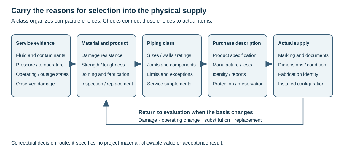
Figure 2.1. The decision route returns to evaluation when damage, operating conditions or the proposed supply changes.
Carbon steel is a common starting point because it combines useful strength, familiar fabrication and broad availability. It is not a neutral choice for every fluid. General corrosion, erosion-corrosion, wet hydrogen-sulfide damage, hydrogen attack and environmental cracking have different causes and require different responses. A predicted general loss of wall may be addressed by allowance and inspection. Cracking can destroy containment without consuming the assumed allowance uniformly. Increasing thickness cannot, by itself, demonstrate resistance to that mechanism.
Strength and toughness are also different properties. A material may have adequate allowable stress for pressure containment and inadequate resistance to brittle fracture at a low metal temperature. Toughness depends on material, product form, heat treatment, thickness and manufacturing history. A low-temperature grade, impact-test requirement or specified heat treatment therefore belongs in the purchase description. It is not enough to change the temperature on a line list while retaining a component selection that was made for warmer conditions.
At elevated temperature the choice may turn on strength, oxidation, microstructural change and the particular fluid environment. Chromium-molybdenum steels provide advantages in high-temperature strength and, under appropriate conditions, resistance to hydrogen attack. Those advantages bring welding and heat-treatment obligations. Carbon-molybdenum steel shows why alloy content alone is insufficient. Improved high-temperature strength does not establish improved resistance to hydrogen attack. The material must address the mechanism that governs the service.
Stainless steel is a family of materials. It is not a single remedy for corrosion. Austenitic grades such as 304/304L and 316/316L differ in composition and resistance to particular environments. Chromium provides the basis for corrosion resistance, but chlorides, deposits, temperature, stress and external wet insulation can create a cracking problem.
A line can acquire harmful chloride contamination from test water or from conditions during shutdown. Sulfur-derived acids formed when sulfide deposits meet moisture and oxygen during an outage present another distinct concern, particularly for sensitized material. Normal operating compatibility does not settle these intervention states.
Low-carbon and stabilized austenitic grades address sensitization in different ways. Neither designation removes every consequence of prolonged thermal exposure. Duplex stainless steels combine ferritic and austenitic structures and offer useful strength and corrosion resistance. Fabrication and phase stability must also be part of the selection.
Ferritic and martensitic stainless steels have their own weldability and embrittlement considerations. Where an adopted class prohibits a family because of these concerns, that prohibition is part of the selection basis. A different stainless grade requires a new evaluation.
Nickel alloys may suit chemical environments for which common stainless steels are unsuitable. They cost more and have their own fabrication precautions. Titanium can provide valuable chemical resistance but demands particularly clean welding conditions and careful consideration of field repair. An alloy with excellent laboratory resistance may be a poor installation choice when suitable fabrication and replacement capability cannot be maintained.
Product form matters beside composition. A cast valve body and wrought pipe of broadly similar chemistry do not have identical manufacturing histories or toughness characteristics. Grey cast iron, ductile iron and cast steel differ substantially in brittle behavior. Likewise, seamless, electric-resistance-welded and electric-fusion-welded pipe are different products.
A longitudinal seam introduces manufacturing and examination requirements that a seamless product does not have in the same form. Whether a welded product is acceptable depends on the service, governing specification, manufacturing route, examinations and applicable design factors. A historical preference for seamless process pipe is not a universal rejection of qualified welded pipe.
The comparison below guides selection. It is not a table of permitted services or temperature limits. It states the reason to examine a family and the condition that can reverse that choice.
Table 2.1. Material-family selection comparisons.
| Material or construction |
Reason to consider it |
What can reverse the choice |
Consequence for the installation |
| Carbon steel |
Familiar fabrication, availability and useful strength |
Unacceptable corrosion, cracking, low-temperature toughness or high-temperature degradation |
Allowance and inspection must address the actual damage; grade, toughness and fabrication conditions remain explicit |
| Chromium-molybdenum steel |
High-temperature strength and resistance to specified hydrogen environments |
Unsuitable alloy level, embrittlement or inability to control fabrication |
Preheat, heat treatment, welding and examination form part of the material choice |
| Austenitic stainless steel |
Resistance to many environments that attack carbon steel |
Chloride cracking, sensitization or harmful outage contamination |
Test water, insulation, marking materials and shutdown protection affect integrity |
| Duplex stainless steel |
Useful combination of strength and corrosion resistance |
Service or fabrication conditions that impair the required structure/properties |
Product qualification and controlled joining must accompany selection |
| Nickel alloy or titanium |
Particular chemical resistance beyond common steels |
Cost, availability, fabrication or repair difficulty; incompatible chemical conditions |
Plan skilled fabrication, inspection and replacement with the initial selection |
| Thermoplastic |
Chemical resistance, low mass and joint systems suited to the service |
Temperature/duration-dependent properties, vacuum, fire, mechanical damage or joint restrictions |
Use the qualified pressure-temperature/joint system and material-specific handling/support |
| FRP/RTR |
Resin-dependent chemical resistance with fiber reinforcement |
Wrong resin/liner, unsuitable joints, cure or loading |
Treat pipe, fittings, adhesives, laminate and procedures as a compatible system |
| Lined steel |
Structural steel with an internal chemical barrier |
Liner damage, permeation, vacuum or discontinuity at joints |
Preserve the barrier through fabrication, transport, assembly and inspection |
Separate pressure wall, damage allowance and delivered thickness
The wall selected for pipe serves several purposes. Pressure design establishes a required thickness for the applicable pressure-temperature condition and material/product factors. Threading or grooving can remove wall. Corrosion and erosion can remove further wall during service. Manufacturing permits a specified variation about nominal thickness. The order in which these provisions are applied matters.
For straight metallic pipe, a useful relationship for thickness accounting is:
In this equation, is the required minimum wall and is the pressure design thickness. The mechanical allowance covers features such as threads or grooves. The corrosion/erosion allowance is . All four quantities use the same length unit.
The associated pressure-wall procedure is taught in its historical ASME B31.3 (1984) context; application uses the governing edition and product provisions. This relationship explains the components of the wall requirement. The governing pressure method, material factors and any minimum structural wall remain part of the adopted design basis. Pressure design develops the pressure calculation and the distinction between process-piping and pipeline methods.
If the product specification permits a fractional negative wall tolerance , a nominal thickness must satisfy
Here is dimensionless. A 12.5% negative tolerance means and leaves at the lower tolerance boundary. This is the historical seamless-pipe allowance used in the worked method. It is not a tolerance assigned to every pipe product. For wall selection:
- Apply the actual specification and manufacturing conditions.
- Then select an available nominal wall that satisfies the result.
Nominal wall, minimum required wall and measured remaining wall are distinct quantities.
The result says nothing by itself about external pressure, flexibility, local attachments, branch reinforcement or component ratings.
A design floor and an inspection limit answer different questions
An adopted class can impose a minimum schedule even when a calculated pressure wall is smaller. That floor may preserve robustness, connection geometry or the construction basis. A successful pressure calculation does not delete it. Conversely, choosing the listed minimum schedule does not establish adequacy for loads omitted from the calculation.
A historical carbon-steel class-design provision illustrates the distinction. Its pressure-only procedure uses minimum design-wall values of 2.54 mm for NPS 3/4–3, 3.05 mm for NPS 4–6 and 3.30 mm for NPS 8–24. Those values apply only within the stated method. Temperature must be no greater than 260°C.
Pressure must be no greater than 2,400 kPa for NPS 14 and below, or 1,380 kPa for NPS 16–24. The provision states pressure in kPa without locally identifying gauge or absolute reference. Its adopted pressure reference and code basis must be established before applying those pressure comparisons. Outside that scope, and where the full load analysis is performed, calculated wall must address the relevant loads.
These are conditions of a particular design procedure, not universal carbon-steel wall limits.
Within that procedure, select the schedule from the applicable design floor plus the class corrosion allowance, with product tolerance, class minimum schedule and other required evaluations still applied. Do not substitute its definitions into another wall procedure.
The procedure explicitly excludes using those design-wall values as arbitrary inspection retirement limits. A new-design floor, an allowance for future loss and a minimum acceptable remaining wall have different purposes. Condition assessment needs the actual geometry, damage and service state, the applicable calculation or assessment method, and the inspection basis. A pipe does not become fit for further service merely because its measured wall exceeds a number copied from a new-design table. Operating integrity develops that assessment; pressure design and load analysis supply the relevant calculation interfaces. Structured design-floor method retains the scoped table and teaching inputs.
Base corrosion allowance on the expected damage over the intended period, including changes with temperature, contaminants, wetting and operation. Localized attack, erosion at fittings, cracking and external corrosion require separate evaluation.
The alternatives are added wall, a more resistant material, a lining, control of the corrosive environment, and inspection or replacement planned around the damage. They can be combined. Added wall is attractive when loss is sufficiently predictable and available thickness remains practicable. It becomes less convincing when the required allowance is large, the mechanism is localized, or the component cannot accommodate it.
An alloy or lining can reduce a particular damage mechanism but introduce joining, inspection or repair obligations. A suitable choice accounts for those consequences. Corrosion resistance is not a single ranking.
Nominal pipe size identifies a standardized size family. It does not state the measured outside diameter in every size. Wall schedule identifies a dimensional series, not a pressure rating independent of material and temperature. For a given outside diameter, increasing wall reduces the internal bore and increases mass. That changes flow resistance, support loads, fit-up and the transition into fittings as well as pressure capability.
Pressure class on a flange or valve is another designation. Class 150 does not mean that the component has a universal allowable pressure of 150 psi. Pressure-temperature ratings depend on the applicable component standard, material group and temperature. Pipe may be evaluated by its calculated wall while a valve or flange is evaluated by a standard rating. The system must satisfy both routes. A component’s material temperature limit, gasket limit or class note can govern before the pipe wall does.
Fittings supplied to match pipe wall require a compatible bore and end preparation. A heavier fitting may be commercially convenient, but a mismatch can require a specified transition without reducing either part below its required minimum wall. Very thin pipe can save material on a long straight run and become uneconomic in a short, fitting-rich arrangement that requires special fittings or taper boring. Standard walls can simplify availability and subsequent replacement. The economic comparison includes fittings, machining, fabrication and maintenance, not just kilograms of pipe.
Carry wall changes into hydraulics, loads and connections
At fixed outside diameter, a thicker wall reduces bore and fluid inventory, increases pipe mass and changes bending stiffness. Recheck flow resistance, liquid-filled test loads, flexibility and supports after a wall change. Greater stiffness can increase forces needed to impose a displacement. Use actual material properties and geometry, including lining, ovality, wall variation and end preparation. A nominal reference section does not establish delivered minimum wall or acceptable remaining wall.
Pipe and tube size labels use different conventions. A 1/2 in outside-diameter tube has a 12.7 mm OD; the selected nominal 1/2 in steel pipe data use 0.840 in OD. A pipe-thread-to-tube adapter needs both end descriptions. Insulation and lining quantities use each layer's actual geometry.
A piping class binds compatible components
A piping class is a controlled set of component selections and conditions for a defined range of applications. It commonly identifies pipe materials and walls by size; fitting and branch arrangements; flange and valve classes; gasket and bolting; joining methods; corrosion allowance; and supplemental requirements such as impact testing, heat treatment or examination. Its service index helps locate a candidate class. The index does not replace reading the class limits and notes.
Class coverage must include coincident pressure-temperature states, cold/cleaning/upset conditions, required sizes and every component family.
A small-bore component or valve can have less available corrosion allowance than the larger pipe in the same nominal class. A class may state that exception explicitly. A common class heading therefore does not establish identical remaining-life provisions throughout the line.
Two wall-selection approaches are useful and must remain distinct. A class can supply walls calculated for its specified full flange pressure-temperature envelope, rounded to standard available schedules. Alternatively, an adopted procedure can permit a wall calculated for the actual line conditions. The latter can reduce weight or cost, but its narrower basis must be preserved in the line record and drawings. Raising the operating condition later cannot be justified merely because the flange has spare rating. The calculated pipe wall and every affected component must be reevaluated.
Joint restrictions belong beside material selection. Threaded or socket-welded connections can be excluded by a service, size or cyclic-loading criterion even when the base metal is otherwise suitable. A class may assign special branches or valve trims for the fluid, require a particular gasket, or exclude a valve type. A special item outside the class needs an explicit description of its material, ratings, ends and service requirements; “special” does not exempt the item from the system’s containment and mechanical obligations. Components and pressure-retaining joints and Branches and small-bore connections explain the hardware consequences.
A supplier alternative, field substitution or replacement can break compatibility at a flange, dissimilar-metal weld, gasket, valve trim or nonmetallic joint. Compare the proposed item with the original selection basis.
Follow a candidate class into the actual item and work
Read the service index together with its identified detailed class, code/application boundary, revision, envelope, size-dependent product rows and attached notes. Similar class names, suffixes or pressure groups from another basis are not interchangeable.
One class method separates construction quality from flange pressure rating. Its construction classes combine component quality, inspection and fabrication provisions selected for severity of service. The piping class must be permitted for the required construction quality. A higher flange rating does not establish that quality, and increasing quality indiscriminately can add cost without supplying a needed function. The adopted requirement and its purpose must remain explicit. The organization's numbered quality levels are not universal grades.
A detailed family can illustrate the selection. Three sour-service candidates share Class 150 flanges and a material-group rating basis. One warm candidate has a 1.5 mm minimum corrosion allowance. Another has 3.0 mm.
A cold candidate also has 3.0 mm. It changes the pipe, fittings and flange products to A333 Grade 6, A420 WPL6 and A350 LF2. It also extends its declared lower temperature from −29°C to −45°C. The changed allowance and changed product condition answer different questions.
Increasing an allowance does not create low-temperature toughness, and retaining the same flange class does not make the component descriptions equivalent.
Their rows continue the decision into pipe wall, end preparation, bolting, gasket, valve description and local service notes. An adopted sour-product certification, particular bolting grades or a verified trim condition is not supplied by matching only the pipe's nominal composition. Dual certification must establish the represented product's required bases. Two standard names beside a similar grade do not prove that the delivered item meets both. The purchase and receiving route later in this chapter preserves those distinctions.
A component note can govern inside the apparent class envelope. In the selected warm candidate, the class range reaches 204°C, while a note attached to its ball valves limits those selected items to 100°C. That selected valve cannot cover a 140°C condition. Its local limit does not define all ball valves; pressure, cold state, material suitability and function still require verification.
Table 2.2. Read the candidate through its dependent engineering decisions.
| Selection step |
Evidence to use |
Consequence to preserve |
| Service and application |
Fluid/state, code boundary, coincident conditions and actual class identity |
Process and pipeline classes can use different product and design bases |
| Class envelope and wall |
Material group, stated pressure/temperature limits, allowance, minimum schedule and applicable calculation |
Component rating or a convenient schedule does not expand the permitted class conditions |
| Local item and segment |
Size range, material/end/trim description and attached notes |
A valve temperature cap, cold product, lining or local fluid segment can govern separately |
| Manufacturing and fabrication |
Product category, certification, joining, PWHT and its qualified exemptions |
A substitution or exemption must reach the fabricator's actual instructions |
| Examination and restoration |
Selected extent/method, service state, actual installed configuration and evidence |
A percentage, drawing revision or class header alone does not establish accepted work |
Pipeline examples make the application boundary particularly visible. Where a detailed class explicitly limits pressure to the lower rating from its stated flange/component bases, both must be evaluated under their applicable conditions. That is an express selection rule within the class; it is not permission to combine unrelated rating tables. Its wall schedules can also depend on design factors that the procedure requires the designer to verify.
If those factors do not apply to the actual line, the wall requires recalculation. The printed schedule depends on its premise. Product categories, manufacturing routes and pigging requirements still travel with that selection. Pipeline and offshore systems develops the system application.
The item roster matters as much as a common wall-data strip. A cold stainless candidate can show larger-size columns in the strip while listing pipe, flanges and valves only through NPS 12. Those columns do not add the missing products to the class. Likewise, a sanitary drain class with ABS pipe, compatible socket fittings and solvent cement explicitly excludes use where steam cleaning is required.
The class may suit the ordinary fluid but not the intended intervention state. A copied metallic schedule strip or an N/A pressure field cannot establish an ABS system's rating. Cleaning and readiness carries the selected intervention basis into work.
The index and detailed class can also disagree. In a matched family, a summary gives code-based PWHT while the detailed sheet states all welds with a particular approved-procedure exemption. In other matched entries, the summary and detail give different temperature maxima. Preserve the actual versions, entries and note conditions and reconcile the applicable basis before releasing the selection.
Taking the larger temperature or the more demanding heat-treatment phrase does not resolve their different meanings. The index's direction to use the detailed class is a reason to examine it. Agreement must not be assumed where the records differ.
The work must use the resolved selection. Some service states distinguish liquid and gas examination extents; some PWHT exemptions require their use to be identified on the fabricator's drawings. A material change in a local process segment, a differently rated soft good or a revised cleaning method can reopen the class relationship without changing the general fluid name. Heat treatment and examination, construction and engineering records preserve those outputs and their verified installed state. Structured class walkthrough records the hypothetical temperature comparison and the decisions it leaves open.
Thermoplastics change stiffness and strength with temperature and duration of loading. Their chemical resistance, low mass and smooth bore can make them attractive, but a room-temperature pressure marking does not establish capability at a warmer sustained condition. Pressure, temperature, fluid compatibility, joint type, vacuum and mechanical support must be evaluated together. The installation can also be exposed to sunlight, fire, impact and temperatures during cleaning that exceed its normal fluid condition.
HDPE is commonly joined by heat fusion, with transitions to metal or equipment made through qualified mechanical arrangements. The pipe material, dimensions, fusion procedure, equipment settings and operator qualification act together. Dissimilar wall thicknesses or materials require evaluation against the qualified procedure before they can be treated as an ordinary same-pipe fusion. General-purpose piping and piping supplied under a particular fire-protection approval can have different joining and acceptance restrictions. A procedure written for one is not automatically applicable to the other.
PVC, CPVC and ABS often use solvent-cemented joints. Surface preparation, compatible cement, assembly and cure establish the joint. A dry-looking joint is not evidence that it is ready for pressure. CPVC has a different temperature capability from PVC, but it still requires a compatible product and service basis.
PP, PVDF and PB provide further alternatives, commonly with fusion or other system-specific joints. Their advantages must be assessed against the actual chemical environment and pressure-temperature condition. The generic word “plastic” does not establish suitability.
A mechanical connection can be convenient for removal or transition while providing different axial restraint from a fused joint. Pressure thrust, thermal movement and support therefore remain part of the choice. Plastic flanges and adapters also respond differently to bolting from steel assemblies. Excessive local compression or poor alignment can damage the nonmetallic component. Support must distribute load without cutting or abrading the pipe and must account for thermal movement, valve masses and the temperature-dependent properties. Support selection develops these consequences, and Fabrication and construction carries them into installation.
FRP or RTR piping contains reinforcement, resin and often a corrosion-resistant internal layer. Resin selection answers the chemical exposure; reinforcement and laminate construction answer structural demands. A change in resin, liner, reinforcement or manufacturing method changes the product. Adhesive and butt-and-wrap joints likewise require compatible materials, preparation and cure. Pipe, fittings, flanges and adhesives from different manufacturers are not interchangeable under an aboveground RTR procedure that prohibits such mixing. That procedure’s scope excludes underground, mechanical-joint and fire-water systems; those variants need their own basis.
Cure is a physical part of joint formation. Temperature, time and the prescribed process affect whether the resin or adhesive achieves the intended condition. Handling or loading an uncured joint can defeat an otherwise sound selection. Chemical resistance may be supported by relevant field experience or laboratory testing, but the compared exposure must represent the intended service. A generic FRP pressure designation cannot identify the resin or prove chemical compatibility.
Concrete piping is a distinct alternative for suitable water, drainage and other applications. Structural form, reinforcement or a steel cylinder, joint construction, exposure and installation loading matter. It should not inherit thermoplastic joining or support assumptions merely because both are grouped as nonmetallic. Buried systems develops the interaction with bedding, soil and installation.
Locate the joining interface and the axial load path

Figure 2.2. Selected upper-wall sections locate fused or bonded interfaces, a reinforced overlay, and separate sealing and retaining features. These are mechanism comparisons, with structured joint relationships.
Butt fusion brings prepared, aligned and heated end faces together. The double bead accompanies the joining interface. Socket fusion heats the outside of a male end and the inside of a socket with their matching tools before assembly. Solvent cementing uses prepared surfaces and compatible cement instead of that heating operation. The similar overlap in panel B does not make those two formation processes interchangeable. Their material, preparation, assembly window, cooling or cure conditions remain with the qualified system.
An adhesive bell joint develops its bond over the prepared mating surfaces. A butt-and-wrap joint instead bridges prepared ends with resin-impregnated reinforcement. A selected construction may also require an inner-surface overlay. An external or internal overlay over another joint is a defined additional construction.
The selected construction must preserve access for bond preparation and examination, including any required inner barrier. An outer wrap cannot compensate for an omitted internal layer or unprepared interface. Joining and construction retain formation, cure and examination requirements.
A seal and an axial restraint answer different questions. An unrestrained O-ring can close a leakage path while permitting the ends to separate under axial thrust. The installation must supply its qualified thrust-resisting arrangement. A restrained O-ring joint adds a distinct mechanical load path, such as its specified threads, clamp, key or retaining ring.
Panel F represents that separation of duties, not a particular interchangeable coupling. The actual engagement, component compatibility and pressure-temperature basis require evaluation. A gasket's visible presence cannot establish the retaining feature's capacity.
Flange adapters and specialty transitions introduce further interfaces. The nonmetallic stub end or adapter joins its pipe through the qualified material process, while the backing flange and bolted seal connect it to another component. A metal transition retains its particular polymer retention, sealing arrangement and metal-end preparation. Each interface needs protection during welding, handling and assembly. The complete product rating requires verification. Neither the metal end nor the straight pipe's pressure calculation automatically rates the entire transition.
Before applying a restraint example, select the installation route. One adopted general-purpose HDPE route requires a fully pressure-rated and fully thrust-restrained mechanical coupling. Under the specified longitudinal-load criterion, the pipe must yield before the coupling separates. This route expressly rejects external restraint as a substitute.
Its fire-protection-approved route instead permits its flange-adapter/backing-ring connections and excludes mechanical couplings and external joint restraints. Those requirements cannot be replaced by the historical seal-only joint's separate thrust-block or burial arrangement. Keep the selected system, approval and load path together through procurement and installation.
Calculate internal pressure from minimum wall and qualified factors
A thermoplastic pipe's internal-pressure evaluation uses its qualified material strength, minimum product wall and service conditions. It answers a different question from the external-pressure stability calculation below. A modulus used to model collapse is not a hydrostatic design stress, and a satisfactory internal-pressure result does not establish vacuum capability, acceptable support spacing or joint qualification.
For a selected historical thermoplastic method, define the standard dimension ratio as
In this equation, is the pipe outside diameter and is its minimum wall thickness. Use the same length unit for both, making SDR dimensionless. A lower SDR describes a greater minimum wall relative to outside diameter. Nominal pipe size is not , and nominal wall is not automatically . Establish the product's actual dimension and tolerance basis; do not assign the historical steel-pipe negative tolerance to every thermoplastic product.
The method can then be written in equivalent forms:
In these equations, is the design-pressure quantity calculated by this method. is hydrostatic design stress for the selected material and qualification basis. , and are dimensionless temperature, environment and joint factors. and use the same pressure unit; and use the same length unit. The equation illustrates the adopted method, not a universal rating for plastics or a current code permission. Establish the pressure reference for an application; the following examples retain the method's psi quantities without using them for an absolute-pressure or gas partial-pressure calculation.
Hydrostatic design basis and hydrostatic design stress have separate roles. In this historical route, the design stress is the hydrostatic design basis divided by two. For the pressure calculation, use the actual qualified stress and its material, temperature, duration and method basis. A tensile-strength value, a short burst result or an elastic modulus cannot replace it.
The stress reference and factor schedule belong together. A second temperature reduction on an already adjusted stress is appropriate only if the selected method requires it. Material designation conventions can help identify a specified product, but they are not a universal decoder of its allowable stress.
The factors also have separate purposes. The evaluation must account for external heating as well as fluid temperature, including solar heating of aboveground pipe. Temperature can reduce pressure capability, while exposure to hydrocarbons can introduce another reduction even where the base polymer remains chemically usable.
The selected joint has its own factor and eligibility. In the historical HDPE route, the environment factor is 0.5 for hydrocarbon exposure, including small quantities, and the joint factor is 1.0 for butt fusion. A PVC/CPVC route instead uses 0.4 for hydrocarbons, 1.0 for solvent-cemented joints and 0.5 for eligible threaded joints. Those are different material and joining bases.
The arithmetic cannot authorize a chemical exposure excluded by the material selection or a joint excluded by size, temperature, service or approval conditions.
A joint-factor entry is particularly easy to misuse. A separate PP/PB/PVDF method lists a 0.5 threaded-joint factor, but its joining instructions state that PP and PB should not be threaded and restrict the PVDF threaded application. The factor does not override that selected negative recommendation or the PVDF restrictions. Likewise, a nonzero temperature factor does not extend the material's declared pressure-service temperature envelope.
Eligibility must be established before calculation with the factor. Conflicting limits need reconciliation. Selecting the largest temperature or the smallest reduction does not resolve them.
For the historical PE3408 route at 100°F, the declared calculation uses psi, SDR 11, , hydrocarbon and butt-fusion , giving psi. Before the environmental reduction, those factors calculate 126.4 psi, while the corresponding historical nonhydrocarbon table lists 125 psi. Resolve the adopted table or calculation basis before application; neither is an actual line approval.
The separate NPS 6 Schedule 80 CPVC table example starts from 280 psi at 73°F for a solvent-cemented nonhydrocarbon reference. Its crude-oil factors at 120°F are 0.4 for environment and 0.65 for temperature, giving 72.8 psi (reported as 73 psi). The reference already includes the solvent-cemented joint; a threaded factor would conflict with that description. This rounding is not permission to round a required limit upward. Structured internal-pressure method and cases.
The system evaluation must continue after the pipe calculation. Actual fittings, valves, flange adapters, flanges and joints require verification at the relevant conditions. A fabricated fitting or flange can have less pressure capability than the associated straight pipe. Chemical compatibility, fusion or cement procedure, cure, examination and readiness remain part of the actual installation.
Surge, external pressure, thermal movement, restraint and sustained support require separate evaluation. The record must retain material stress, minimum-wall/SDR basis, factors, temperature and exposure conditions. A changed fluid, joint or operating state then reopens the affected result. Components, Mechanical response, Supports and Readiness carry those interfaces.
This thermoplastic method does not supply an FRP laminate pressure criterion or replace its distinct reinforcement and qualification basis.
Vacuum checks why stiffness and geometry matter
Internal pressure capability does not establish external-pressure capability. An unconstrained thermoplastic pipe can collapse when the pressure outside exceeds that inside. A useful elastic relationship for illustrating that sensitivity is
In this equation, is collapse pressure. The elastic modulus applies at the relevant temperature and loading duration. Poisson’s ratio is , wall thickness is , mean pipe diameter is , and the ovality factor is . and use the same pressure units, and use the same length units, and and are dimensionless.
This relationship is for unconstrained pipe. It does not evaluate burial restraint, fittings, joints or an actual long-term vacuum rating. Modulus must not be borrowed from a short-duration table for a prolonged hot exposure.
Collapse pressure varies cubically with wall-to-mean-diameter ratio and directly with the applicable modulus. This elastic result is not an allowable external pressure.
Actual ovality, duration, temperature, safety provisions and the qualified system limit still govern application. A suggested reduction factor in an adopted method must retain its stated purpose; it should not silently become a universal pipe rating.
Compare duration and SDR without converting strength into an allowable

Figure 2.3. Historical HDPE buckling-strength duration curves.
HDPE response under external loading depends on duration as well as wall geometry. The historical curves compare SDR 11, 17, 26 and 32.5 on logarithmic time and buckling-strength axes. The upper 100-to-150 psi tick interval is irregular relative to the lower decade scale. The native recovery calibrates that interval separately to its printed endpoint labels.
It does not extrapolate the lower pressure scale into that interval. Strength decreases as duration increases; the lower SDR curves retain greater strength in the plotted comparison. The curve label is buckling strength without safety factors, not an allowable external pressure.
The bounded recovered samples retain selected graphic readings with approximately ±5% pressure and ±0.05 decade time reading envelopes. At one hour, SDR 17 is about 32.5 psi while SDR 26 is about 10 psi. Near 1,000 hours the corresponding graphical readings are about 17.1 and 4.7 psi. These are readings of the historical curves, not ratings of a selected pipe. Intermediate connecting lines reproduce the picture. Unquantified intersample curvature and the graphical reading limits remain with the data.
The time axis spans 0.01 to 10⁶ hours. The panel says experimental curves are extrapolated to 50 years, but does not mark the point where each experimental record becomes extrapolation. Its endpoint marker labeled h is near 3.35×10⁵ hours on the recovered primary axis. The secondary 50-year annotation is not an exact hour conversion at that marker. Do not manufacture an exact 50-year pressure or extend the curve to an unplotted duration by calculation from that label.
The visible original panel and surrounding context do not establish a specific HDPE grade or test temperature for these curves. A nearby PE3408 internal-pressure factor table does not qualify this different collapse dataset. Before transferring a curve to design, establish the actual grade, temperature, ovality, duration/history, applicable dataset and safety basis. Temperature and ovality are significant. Historically common safety factors of 2–2.3 are observations, not universal required factors. The manufacturer's vacuum/external-load basis remains necessary.
External water load and internal vacuum can act together. A historical example combines 10 psi of water loading with a 5 psi partial vacuum to give a 15 psi external differential. That load description does not establish acceptable collapse margin. Evaluation of the selected pipe and installation requires consistent pressure references and simultaneous states. Mechanical analysis and Buried installation carry support, ovality and external conditions beyond the bare graphical comparison.
Lined steel divides structural and chemical duties
Lined steel uses the metal to carry structural loads and an internal lining to separate the fluid from that metal. Plastic, cement and other linings have different chemical, temperature, abrasion and vacuum behavior. The apparent advantage of a chemically resistant barrier is lost where handling, a joint, a branch or a field operation exposes the steel.
A lined system therefore needs details that continue the barrier through fittings and end connections. Shop-lined spools can limit field fabrication options. Cutting, welding or heating near the liner may damage it. Flange assembly must protect the liner and follow the specified sealing arrangement.
Thermal movement or permeation can affect a liner even when the steel pressure boundary remains intact. External corrosion still acts on the structural metal. These are separate duties and separate possible failure paths.
Inspection and repair need to recognize that separation. A sound external surface does not prove an intact internal barrier, and a pressure test does not establish that a chemically resistant liner is undamaged everywhere. Selection of lined pipe should include methods to assess internal condition and perform holiday or other applicable checks, repair and replacement. Corrosion management and Examination, testing and readiness develop the protection and verification routes.
Record the defect, its location and the actual product criterion
A visible FRP observation needs its location and physical extent before a disposition can be made. A body or collar defect is a different population from a defect at the thread crest, root or cut end. The following historical criteria describe one FRP manufacturing/product route; adopt the complete product and inspection basis before using them on an actual pipe. A pressure marking alone does not establish that basis.
| Region / defect |
Observation |
Criterion in this route |
| Pipe Body and Collar / Burn |
Thermal decomposition evidenced by distortion or discoloration of the surface |
20% area if lightly blemished; 5% area if moderate burn of outer resin layer structural roving |
| Pipe Body and Collar / Chip |
Small piece broken from edge or surface |
Permitted if laminate has not been fractured |
| Pipe Body and Collar / Crazing |
Fine cracks at or under the surface seen by the unaided eye |
None permitted |
| Pipe Body and Collar / Cut Roving |
Outer rovings broken or cut owing to scraping or scuffing, or manufacturing process |
Maximum 3 per pipe with maximum size of 1 in.², such that the wall thickness is not reduced below minimum |
| Pipe Body and Collar / Dry Spot |
Area where reinforcement was not thoroughly wet with resin |
None permitted |
| Pipe Body and Collar / Fracture |
Rupture of laminate without complete penetration. Visible as lighter-colored area of interlaminar separation |
None permitted |
| Pipe Body and Collar / Pits(pinholes) |
Small craters in the surface |
Maximum 1/16 in. deep, no limit on number |
| Pipe Body and Collar / Resin Drip |
Resin protrusion |
Maximum 1/8 in. high, no limit on number |
| Pipe Body and Collar / Restriction |
Any restriction in I.D. of pipe: paste, epoxy or wax, lump, foreign matter |
None permitted |
| Pipe Body and Collar / Scratch |
Shallow mark caused by improper handling |
No limit on number if reinforcement is not exposed |
| Threads / Air Bubbles |
Small bubbles at crest of threads |
Maximum size 1/8 in.: One allowed. Maximum size 1/16 in.: 10 allowed |
| Threads / Broken |
Light patch at the root of the thread |
Maximum size 1/8 in. in any direction and one allowed per pin |
| Threads / Chips |
Areas where over 10% of thread height is removed |
Maximum 3/8 in. long in one thread per connection, none permitted in LC area |
| Threads / Cracks |
In direction of thread axis |
None permitted |
| Threads / Flat Thread |
Area where top of thread is broken or ground off |
Maximum 3/8 in. long in one thread per connection, not to exceed 10% of the thread height. None permitted in LC area |
| Threads / Squareness |
Cut end angle perpendicular to pipe axis |
Maximum 1/16 in. variation in end |
| Threads / Finish |
Finish of cut end |
No sharp edges. No exposed loose fiber. No protrusions. No impact areas |
A permitted chip still requires an unfractured laminate. The cut-roving allowance includes both its count/area limit and the minimum remaining wall. Meeting one does not waive the other. Pits specify depth, resin drips height and thread damage length or directional size.
Keep those dimensional meanings separate. The burn-area percentage needs its actual area reference and severity interpretation. The thread-chip and flat-thread exclusion in the LC area requires that region to be identified from the adopted product basis; this table does not define it.
Structured defect descriptions and limits preserve the separate populations and quantities.
An excluded defect is not made acceptable by filling or wrapping it without a qualified disposition. Manufacturer-specific repair instructions, compatible materials, preparation, completed cure and the required examinations/tests govern a permitted repair. Severe damage can require replacement rather than local repair. Keep original observations and the disposition with the item record so subsequent work distinguishes an as-supplied criterion, a repaired condition and service damage. Nonmetallic joining and examination, Condition assessment and Intervention carry those different questions.
Qualify the delivered product in its final condition
Qualification must represent the selected product, manufacturing route and final delivery condition. Production evidence must connect delivered items to that basis; sampling before final treatment does not automatically represent the finished item.
A report must define the population it represents. A heat identifies steel from a particular making operation. A production lot can add requirements for item type, size, wall and finishing or heat-treatment batch. Some procedures permit specifically matched heats or several controlled furnace loads to share a lot.
Others require one heat and one treatment batch. Those permissions have their own conditions. A convenient collection of items with the same grade marking is not necessarily one qualified population. A selected high-yield wrought-fitting procedure defines matched heats.
Every reported element must be within ±10% of its mean across the selected heats. Where a shared lot is permitted, the finishing must be the same. Additional heats retain their specified tests in the most worked base-metal and weld regions. Matching CE values alone does not establish that element-by-element relationship.
Representative locations also matter. A formed fitting can have compressed and tensioned regions, a transition and a tangent. A fabricated fitting adds weld and heat-affected regions. A flange specimen can come from the hub or a representative prolongation, while a plate blind can use its parent plate. The required sample must represent the applicable working and heat history, not merely be the easiest piece to remove. Keep the item, population, location, orientation and final condition attached to each result.
Check the property window rather than reward the largest number
Specified minimum yield strength, measured yield strength, tensile strength and design allowable stress have different roles. The specified minimum belongs to the selected grade/design basis. A measured value characterizes the tested material under its test conditions. An adopted product specification can bound that measured value above as well as below, and can limit its ratio to ultimate tensile strength. A larger measured yield strength does not authorize raising the design allowable or deleting a required product condition.
For a selected high-yield butt-welding fitting basis, the added upper bound is 20,000 psi above specified minimum yield strength, and each specimen's yield-to-tensile ratio shall not exceed 0.90. A separate high-yield seamless pipe basis uses an excess of 21,700 psi, stated also as 150 MPa, with a ratio limit of 0.90. A low-yield pipe/butt-welding fitting basis uses an excess of 25,000 psi and a ratio limit of 0.85, with stated exclusions for flanges and certain branch fittings. These are separate product requirements. Taking the largest excess and the largest ratio from different specifications would create an unevaluated fourth basis.
For a bounded calculation under the first of those bases, let be the specified minimum yield strength, the measured yield strength and the measured ultimate tensile strength. Express all stresses in the same unit. The two upper-bound checks are:
Here ksi and apply only to this selected fitting example. The ratio is dimensionless. The product's minimum strength, elongation, test method and other requirements still apply. The measured values must come from the specimen and condition specified by that product basis. A room-temperature result is not an elevated-temperature guarantee unless that assessment has been established.
Structured qualification methods retain the scoped comparisons.
The finished manufacturing condition travels with this evidence. A specified normalizing, quenching and tempering, or solution treatment is not supplied by a grade name alone. Where qualification also assesses a later fabrication heat exposure, the separately treated specimen and its results represent that additional state. They do not make the nominated exposure a universal field heat-treatment cycle. Joining and heat treatment retains the actual procedure and examination basis.
Use the composition model named by the selected basis
A chemistry limit can apply to individual elements and to a weighted composition index. Each answers its defined question. The index does not replace every element limit or establish all mechanical and service properties. Keep heat/product analysis, units and the named model together. Two indices calculated from the same certificate can have different formulas and purposes.
One selected high-yield wrought-fitting basis uses the following carbon-equivalent expression:
, Mn, Cr, Mo, V, Ni and Cu are the numerical weight percentages of carbon, manganese, chromium, molybdenum, vanadium, nickel and copper. Enter 1.20 for an analysis of 1.20 wt% manganese, rather than the mass fraction 0.0120. Report CE with that same percent-number convention. CE is an equivalent composition value, not the measured carbon content.
For this selected fitting basis, CE shall not exceed 0.42. A different flange basis states 0.43. That different product limit must remain with its own specification. A pipe specification stating a limit of 0.19 does not authorize evaluating that limit with the CE equation above.
Establish its actual model and applicable analysis basis.
Duplex selection adds another composition screen. Under a specifically adopted fitting/flange basis, define:
Here , and are numerical weight percentages of chromium, molybdenum and nitrogen. PRE is a composition index, not a corrosion rate or a predicted service life. For the selected 22Cr products in this basis, PRE shall be at least 33 and nitrogen shall be 0.14–0.20 wt%. The specified grade and remaining product requirements also apply. Its selected 25Cr products have a minimum PRE of 40. Do not assign the 22Cr nitrogen range to every 25Cr grade by analogy.
A selected duplex pipe method instead defines a tungsten-adjusted index:
In this equation, is numerical wt% tungsten. Use the actual index required for the selected grade and product analysis. Do not substitute the larger calculated index or transfer limits between formulas. Missing tungsten is not evidence of zero tungsten.
Chemistry does not establish the achieved phase condition
A duplex product also needs the required metallurgical and manufacturing condition. Solution annealing and water quenching, followed by the specified surface treatment, establish a different supply state from a cold-worked or repaired item. A selected product procedure limits cold sizing after final heat treatment to 1.5% reduction in cross-sectional area. It limits cold bending for straightening to 2 degrees.
It explicitly excludes using cold work to enhance mechanical properties. Those limits retain that procedure’s measurement and product scope. They are not a general allowance for field bending. Its mechanical tests then represent the final solution-treated, sized and straightened condition.
A strength result from a different stage cannot silently qualify that final product.
Phase evidence has its own method and population. One fitting/flange product basis requires the average ferrite content of each tested base, weld-metal and heat-affected region to be 30–65%. A separate pipe basis uses 35–55% for each region and specifies microscopic point counting or approved quantitative image analysis after final treatment. Those ranges are separate product criteria.
The welding-procedure example in duplex joint qualification has its own 35–65 vol% condition. Ferrite Number is also a different measurement scale. Neither the procedure range nor FN can replace a required product-region measurement.
Apply the selected criterion to each required region; a pooled average cannot establish that all regions pass. Sampling must follow the specified microscopic or other approved method and representative locations.

Figure 2.4. Chemistry, finished properties, product phase and application exposure are independent evidence branches. Each must address its selected scope; a larger number in one branch does not resolve missing or failed evidence in another. Changes to the product or its state return the affected evidence to evaluation. Structured methods and teaching data preserve the scoped calculations and unresolved conditions.
Retain specimen conditions and both impact-energy limits
Impact evidence requires a temperature, specimen size and orientation, represented material region and applicable acceptance basis. A three-specimen mean and an individual minimum are different requirements. A low result cannot be hidden by two high results where the adopted method requires both. Specimen preparation also matters: a product basis may forbid flattening, permit it, or allow it only below a stated available specimen size. Subsize energy adjustments likewise differ between procedures; a linear size proportion from one must not replace another's tabulated adjustment.
A selected high-yield fitting example applies to grade SMYS 52 ksi and wall no greater than 1.0 in. It requires full-size specimens tested at −50°F. Average absorbed energy must be at least 27 ft·lbf, and the individual minimum is 24 ft·lbf. These conditions belong together. Its base-metal, weld and heat-affected specimens have their stated orientation and region rules. Changing size, grade or wall can select different requirements.
A separate low-yield product's missing impact-energy/test-temperature endpoint must remain unresolved. A usable high-yield or duplex table cannot fill it. Where prose and a table provide different limits, preserve their identities and resolve the applicable basis before release. Taking the lower value for convenience, or the higher one as an unexplained blanket precaution, does not establish which test was required.
Test the intended exposure as well as the alloy description
An environment-specific qualification adds evidence that a composition screen cannot supply. A selected duplex pipe method distinguishes sulfide-stress-cracking production tests from higher-temperature stress-corrosion-cracking and pitting prequalification. It defines the relevant water composition, gas exposure at test temperature, specimen surface condition, applied loading, duration and observations. A nominally identical alloy tested against another water state or at a different temperature is not automatically comparable.
The selected SSC and SCC bend tests put the manufactured inner surface in tension. Applied stress is 100% of measured actual yield strength at the test temperature. Displacement is verified on suitably strain-gauged samples. Under this basis, a published beam formula does not replace that displacement verification.
This is a test-loading condition, not the design allowable for installed piping. The selected SSC duplicate tests per heat/condition also differ from the SCC and pitting triplicate tests used on the first two heats for prequalification. Retain the purpose and population instead of merging the sets into a generic number of tests.
Exposure control affects what the result represents. The procedure retains its specified water/gas conditions, pH observations, temperature, duration and solution-to-specimen area ratio. A minimum of 30 mL/cm², for example, is a volume per identified specimen surface area within that test method. It is not a fluid concentration or plant dosing instruction.
Its minimum 720-hour exposure is not a prediction of operating life. Crack examination, localized/pitting observations and cleaned coupon weight loss answer different questions. A favorable general-loss result cannot erase an unacceptable localized feature. Corrosion management and operating condition assessment develop those damage distinctions.
Procurement, fabrication and change should preserve the conditions that made the evidence relevant. A proposed heat treatment, product substitution, changed chemistry or new exposure reopens the affected tests and comparisons. Keep unresolved conditions visible in technical records, with the actual item and its represented population, so a replacement does not inherit a permission that the original evidence never supplied.
Translate selection into requirements that can be verified
Supplemental requirements often do the work that a base material designation cannot. Low-temperature toughness can require a specified test temperature, specimen location and acceptance basis. Sour-service or other aggressive environments may require composition, hardness, manufacturing or test provisions. Manufacturing-route and weld examinations can distinguish otherwise similar pipe products. These conditions belong in the purchase package before manufacture, where the required samples, heat treatment and examinations can be planned.
The following table shows the chain of information. It is an authored purchase checklist, not a substitute for a governing specification.
Table 2.3. Selection decisions carried into purchase.
| Decision carried into purchase |
Supply description |
Evidence or receiving question |
| Material and product |
Standard/edition, grade, product form, manufacture and delivery condition |
Does the marking and identified report describe the ordered product? |
| Geometry and rating |
Size, actual dimensional standard, wall/class, ends and tolerances |
Are dimensions, bore transitions and mating ends compatible with the intended assembly? |
| Service supplements |
Toughness, hardness, heat treatment, examinations or other adopted conditions |
Do the reports show the required conditions and results for the represented material? |
| Nonmetallic compatibility |
Compound/resin/liner, fittings, adhesive or fusion system and procedures |
Are the supplied items within the qualified system and permitted combinations? |
| Preservation |
Cleanliness, end/facing/thread protection, segregation and shipping provisions |
Has damage, moisture, contamination or loss of identity defeated the intended condition? |
| Traceability and exceptions |
Heat/item identity, required documents and approved substitutions |
Can each affected item be connected to its evidence and actual accepted description? |
A certificate of compliance and a certified material test report provide different information. A compliance certificate states conformity under its specified basis. A material test report records the required tests, examinations, treatments or repairs and identifies the material represented, including its specification and heat identity. The required form and contents depend on the product and purchase basis. The name “certificate” does not establish that a document contains the necessary results or covers the delivered item.
Identification must survive manufacture, transport, storage and fabrication. Permanent markings, transferred identity and controlled segregation serve different stages. Color coding can aid recognition but cannot replace the traceable product identity when that identity is required. Marking itself must be compatible with the material.
Harmful contaminants or injurious stamps can damage a selected stainless product. End protectors and clean packaging protect more than appearance. Damaged bevels, threads or gasket faces create assembly problems. Moisture or debris can compromise cleanliness and preservation.
Receiving checks must resolve dimensions, item/heat identity, delivery condition, documents, damage and contamination before an item loses its separate identity in a spool. Reports without the represented item relationship cannot establish installed properties. Welding, construction and records continue that traceability.
A proposed substitution should reopen the decisions it affects. A different grade can change allowable stress and welding. A different wall changes bore, weight and fit-up. A new gasket or valve trim changes service compatibility.
A different resin or manufacturer can change joint qualification. Replacement in kind is useful only after confirming what “kind” includes and whether the original basis remains suitable. Damage, changed operating conditions or a revised manufacturing restriction can require a new material decision even when the old item can still be purchased.