Chapter 16 — Coatings and corrosion management
Select external coating, galvanizing, internal lining and inhibition for their different threatened surfaces and degradation mechanisms. The same pipe can need several functions. External film adhesion/continuity, process-side chemical access and cathodic-protection current access require separate verification. Material/allowance selection establishes the containment basis; condition assessment establishes in-service damage evidence.
Define the environment and the complete protection system
Atmospheric exposure, immersion, ground contact and the environment beneath insulation have different demands. Temperature affects application, cure and service compatibility. A pipe's normal temperature is not its only relevant condition. Intermittent operation, steamout, shutdown and nearby heat can also matter. The selected primer, intermediate and finish coats, lining or jacket-related protection must remain suitable for those conditions and for the substrate material.
A coating schedule connects those inputs with a complete system. Its preparation grade, profile, material combination, layer thicknesses, application conditions, overcoating interval, cure and examination belong together. A finish-coat name without the underlying preparation and primer does not define that system. Replacing a product or reducing a layer can alter intercoat adhesion, permeability, cure or mechanical response even if the finished color is unchanged.
Different items can have different exclusions. Nameplates, code markings, gasket faces, threads, weld preparations, approved factory-coated equipment and particular galvanized or nonferrous items may need protection from paint or follow a separate route. Some insulation weatherproofing is itself a specified surface system. Painting every accessible metal-looking surface can destroy identification or joint function while providing no demonstrated additional protection. Joints and components and identification and records retain those interfaces.
Buried selection adds soil moisture/resistivity, soil stress, contamination, potential biological attack, diameter, service temperature, field-joint method and inspection access. Shop application can improve control of substrate preparation, heating, application and testing. The installed result still depends on field-joint coating and handling. An excellent shop coating cannot compensate for an unprepared weld area or a damaged sleeve after lowering.
Service and lifecycle cost belong in the comparison. More elaborate application can be justified by inspection difficulty after burial or the consequence of a protection failure. A low-cost field wrap may impose temperature or cathodic-protection limitations. A thicker, tougher covering can resist handling damage while requiring a suitable adhesion and joint-restoration method.
Establish the substrate before applying the film
Remove oil, grease, salts, dirt, spatter and loose rust by the selected substrate-compatible preparation. Salt washing and abrasive scale removal address different contaminants; blasting does not establish soluble-salt/oil removal or the required profile.
Cleanliness grade describes the prepared surface under its specified evaluation method. Profile describes the surface roughness needed by the coating system. Blast grades such as Sa 1, Sa 2, Sa 2½ and Sa 3 have different defined preparation conditions. The selected system determines the required grade.
Manufacturer-required profile is measured by its accepted method. More aggressive roughening is not automatically better. Roughening must remain suitable for the coating thickness and bond. It must not reduce the pipe below its required wall.
After grinding/dressing, verify remaining required metal wall and restore cleanliness/profile before coating. Film cannot repair structurally unacceptable pipe.
Stainless steel, galvanized steel and nonferrous metals have substrate-specific preparation. Abrasives and tools that leave iron or chloride contamination on stainless surfaces can defeat their intended condition. A galvanized surface can need removal of zinc salts, grease or a suitable pretreatment before painting. A process accepted for carbon steel is not automatically suitable for these substrates. Light abrasive preparation, washing, solvent or detergent methods are selected under the complete coating/material route.
Preparation has a time and environment condition. Prime before corrosion or recontamination reopens the surface. One painting route normally primes within four hours of blasting. Another specifies no more than eight hours after preparation and requires renewed blasting if rust develops earlier. These are locally specified windows, not a universal guarantee that an exposed surface remains acceptable for either duration. Observe the actual surface before the next layer and preserve its selected acceptance condition.
Application, cure and thickness are controlled operations
Mixing ratio, allowable thinner, application method, mixing and application conditions, overcoating interval and drying/cure follow the material's instructions and the adopted specification. A coating that is dry to touch may not be fully cured or ready for handling or service. A compatible topcoat cannot restore a contaminated or improperly cured primer simply by covering it.
Surface temperature matters separately from air temperature. A particular new-equipment painting route requires the surface to be at least 3°C above surrounding-air dewpoint. Relative humidity must not exceed 85%. Its explicitly agreed local-condition provision provides the exception to those conditions. The same route has other temperature, weather, light and surface-moisture restrictions. An air thermometer alone cannot establish that a cold metal surface is free of condensation.
A separate blasting route requires the surface to be more than 3°C above dewpoint; do not replace its strict condition with the painting route's at-least condition.
Application method affects local coverage. Spray can coat large areas efficiently, but complex geometry can create overspray, dry spray, sags or poorly covered recesses. Brush application can work paint into corners, welds, edges and crevices. Roller application has its stated surface and priming limitations. Stripe coats address areas whose geometry tends to leave thin coverage. A visually coated edge does not establish the minimum film thickness there.
Wet-film observation during application and dry-film measurement afterward are different stages. The specified measuring technique, instrument, calibration and sampling pattern determine the result. Added compatible coats can repair inadequate thickness only after the required preparation and within the material's application/recoat method. Painting over rain, dust or condensation on an uncured coat requires its stated removal/recleaning disposition rather than assuming that a later coat seals the problem.
Welding and coating also have a sequence. For welding and coating:
- Keep specified weld preparations and future weld areas free of coating.
- Protect finished film from hot work.
A test basis can require uncoated welds until its pressure test, with a bounded primer exception. Another permits a painted spool only under its examination and non-sensitive-test conditions. Joint formation, construction and testing establish which selected sequence is applicable. The resulting field-joint coating must restore the chosen system rather than merely match its color.
Galvanizing and organic coating have different manufacturing routes
A galvanized surface uses a zinc coating with its specified substrate preparation, deposition, coverage and adherence. Hot-dip and mechanically deposited zinc have different processing applications. They are not interchangeable names for a painted zinc-rich film. The fabrication and coating method must suit the item's material, geometry and mechanical requirements.
For galvanizing, complete permitted welding first. After later damage or authorized hot work, use the specified repair. Zinc-coated high-strength bolts, nuts and washers require the applicable grade-specific route. A specification can require mechanical zinc coating for one group and exclude galvanizing for another. Thread clearance, retapping and subsequent assembly condition must agree with that route. Coating every high-strength fastener by the same process can change both its manufactured condition and its fit.
Galvanized acceptance covers coverage, adherence, thickness/weight, distortion and embrittlement; appearance alone is insufficient. Its permitted magnetic thickness or coating-weight method does not override an FBE method's magnetic-gauge exclusion.
Repair of damaged zinc coating follows a specified surface preparation and repair system, such as an applicable zinc solder, zinc-dust paint or sprayed-zinc method. A repair product's thickness and application requirements remain those of that method. Repair is an established protective condition, not proof that every repaired area has the identical manufacturing history of the original hot-dip layer.
Storage must avoid retained moisture and chemical contamination. Shipping treatment and later paint require compatibility with the actual zinc surface and selected pretreatment/primer.
Buried pipe: coating continuity, adhesion and cathodic protection
A buried coating protects the pipe from an environment that is difficult to observe after installation. A holiday is a discontinuity through the coating to the metal detectable by the specified test method. Adhesion is the bond at the relevant interface. A coating can be continuous but poorly bonded, or bonded in most places while containing a local through-defect. Thickness, cure, continuity and adhesion therefore need separate evidence.
An adopted buried-steel route can require coating and cathodic protection together. Coatings can develop holidays during handling or later service. Impressed-current or sacrificial-anode protection then has its specified electrical and corrosion-control role. The coating material and its disbonded geometry can affect current access. Certain tape systems can shield cathodic-protection current, so dielectric strength alone is not the whole selection argument. The cathodic system, isolation interfaces and inspection remain suitable for the actual pipeline or plant-buried configuration in buried piping.
Tape, extruded polymer, FBE and heat-shrink field-joint systems have different application and service behavior. A tape coating combines its selected mastic and backing over a prepared/primed surface. High service temperature or disbonding can limit its suitability. Heat-shrink sleeves use their selected backing and adhesive/mastic with controlled preparation and heating at field joints. Their application does not automatically restore another coating's full qualification.
A field-joint tape system requires its qualified preparation, pipe/tape temperatures and overlap onto sound shop coating. It is distinct from FBE pipe preheat/powder cure; cutbacks or heating conditions cannot be transferred between methods.
FBE is a thermally cured epoxy system whose powder identity, storage, substrate preparation, controlled heating and application determine the film produced. The manufacturer's application temperature and any post-cure are part of the method. Protect bore and bevels from contamination and retain the required cutback and transit protection. Powder batches and any permitted recovery/reuse remain traceable. Mixing brands or reclaiming material by an unqualified method changes the production basis.
Polyethylene and polypropylene systems can use two or three layers. In a three-layer arrangement, the prepared steel receives its primer. An adhesive connects the primer to the outer polymer coating. The outer layer provides its specified protection.
In a two-layer arrangement the adhesive can connect directly to the steel. Some naming conventions also call that layer primer. The label alone does not establish the number, materials or function of the actual layers.
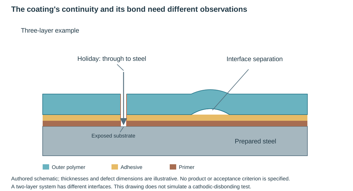
Figure 16.1. Authored schematic of a three-layer example. A holiday reaches the substrate. An interface separation is a different defect. Layer thicknesses, defect dimensions and the particular materials are illustrative. The figure does not prescribe a product or acceptance level, and a two-layer system has a different arrangement. Structured protection methods retain its condition distinctions.
Apply the complete qualified thickness schedule
One adopted external PE/PP system specifies the following minimum total thicknesses. They apply to that qualified system, including its layer and application requirements, rather than to every polymer-coated pipe.
Table 16.1. Conditional PE and PP total coating thicknesses, with structured schedule and conditions.
| Nominal diameter DN |
PE total minimum, mm |
PP total minimum, mm |
| ≤100 |
2.5 |
1.8 |
| >100 and ≤250 |
2.7 |
2.0 |
| >250 and <500 |
2.9 |
2.2 |
| ≥500 and <800 |
3.2 |
2.5 |
| ≥800 |
3.7 |
2.5 |
These totals do not supply primer/adhesive layer thicknesses, which follow the qualified application procedure. Lower PP thickness does not establish superiority to PE; temperature, adhesion, impact, indentation, aging and cathodic-disbonding conditions also govern.
Qualification and production observations answer different questions
Coating-system qualification establishes the selected materials and application arrangement within its tested conditions. Applicator qualification establishes that the production method can deliver the required system. Production controls then establish the actual batch, surface, heating, interlayer timing and finished-film condition. Changing the system requires its specified requalification. One good qualification sample does not establish every production pipe.
Delivered coating evidence must identify the product, substrate condition and actual applied system. Items made during a process deviation require their specified disposition; a prior passing qualification does not release them. Coating must not hide dents, damaged bevels or unacceptable base material.
Finished-film observations include appearance, thickness, holidays, adhesion and cure. FBE qualification can use calorimetry for degree of cure and microscopy for voids or foaming. Knife or pull-off adhesion tests evaluate their specified interface and failure behavior. A cohesive failure within a sound film differs from adhesive separation at the steel, while a honeycomb void structure can have another unacceptable meaning. The test method and criterion determine the evaluation. “The coating was hard to lift” is not a complete report.
Mechanical and exposure tests add further questions. Impact and flexibility assess responses under their test conditions. PE and PP can have different impact temperatures, indentation limits and peel-resistance requirements. Thermal or ultraviolet aging assesses retained properties under its defined exposure. Cathodic-disbonding tests measure the extent of loss of bond under the specified imposed conditions and test temperature. A favorable result from one exposure cannot be substituted for another required one.
Holiday detection uses a coating-appropriate method, electrode, return/earth connection, voltage, coverage and surface condition. The test is checked by its specified calibration or known-defect procedure. Too casual a scan can miss a discontinuity. A universal high voltage is not a justified improvement.
The selected coating and thickness determine the method. A dry external surface is required by a specified high-voltage FBE route. Coating repaired after the initial scan receives its required reexamination.
Thickness methods are similarly specific. A stated FBE route requires calibrated eddy-current or electromagnetic techniques and excludes its named magnetic gauges. A galvanizing route permits its prescribed magnetic instrument or coating-weight method. The FBE production pattern can specify longitudinal positions and four circumferential locations, including a weld position on welded pipe. A convenient reading on a smooth patch does not establish that required coverage. Retain the actual method terminology, calibration and population rather than select an instrument by a generic “coating gauge” label.
Rate the through-film and across-film observations separately
A cured FBE film can have a favorable outer appearance while containing voids or interfacial contamination. The selected microscopic route examines the cross-section and the coating–steel interface at 30–40×, using coating chips from test pipes where appropriate. Through-film means a section perpendicular to the pipe surface; across-film means a section parallel to it. The two directions are separate observations of the coating structure.
In the adopted finished-coating route the maximum degree is 2 in both directions. The associated production route also specifies maximum degree 2. Each direction must meet its own limit; do not average the grades. Microscopic conditions and criteria. Report interface contamination separately; a favorable foam grade does not waive an unacceptable interface or establish degree of cure, adhesion, impact or holiday performance.
Retain separate grades and interface-contamination findings with sample/population identity. Failed specimens require the adopted suspect-population disposition; sampling damage requires qualified repair and reexamination.
Select a holiday method from the actual coating and test stage
A holiday test observes a conductive path through an insulating coating to its metallic substrate. The instrument, electrode contact, earth connection, coating condition, coverage and voltage affect what that observation means. Excessive voltage can damage a film that was sound before testing. Insufficient or incomplete testing can miss a discontinuity. A dry high-voltage scan and a wet-sponge method are therefore selected parts of a coating procedure, not interchangeable ways to obtain the same certificate.
Table 16.2. Three distinct adopted holiday-test bases, with structured conditions and limitations.
| Bounded application |
Test basis |
Conditions that remain part of the method |
| Specified underground coating route before burial |
DFT below 20 mils: low-voltage wet sponge; DFT at least 20 mils: high-voltage spark |
Actual dry-film thickness selects the band; thin-film spark damage warning and complete coated pipe/joint/fitting examination remain |
| Specified FBE line coating |
2.2 kV at nominal 475 μm; 3.6 kV at nominal 725 μm |
Direct earth on pipe, moisture-free surface, full coverage at no more than 0.3 m/s; voltage calibration at least twice per shift |
| Specified PE/PP line coating |
1 kV per 0.1 mm of coating, capped at 25 kV |
Direct earth on pipe, dry surface, full coverage at no more than 0.3 m/s; voltage check at least once per shift |
Twenty mils is 0.508 mm, using 1 mil = 0.0254 mm. That route also contains a product/coat-count table assigning high-voltage testing to two-coat arrangements.
Its listed figures are maximum thicknesses. Its other coat-thickness notes do not guarantee a total of at least 20 mils. Retain this local inconsistency rather than infer actual DFT from coat count or invent a voltage setting.
The FBE settings and PE/PP per-thickness rule are separate test bases. Apply the PE/PP 25-kV cap even where its thickness calculation is higher; voltage alone proves neither coverage nor coating qualification.
The selected FBE flexibility qualification requires continuity after its prescribed deformation: strain factor 0.02 at 0°C and 0.03 at 20°C, with any subsequent detected holiday constituting failure. Those laboratory results do not qualify the installed pipe's stress range or production bend; handling, bending and supports need their actual geometry/service assessment. The complete adopted test procedure controls specimen preparation, deformation and detection. Qualification conditions.
PE/PP peel qualification also depends on operating band and test temperature. In the selected below-20°C operating band, testing at 23±2°C requires resistance greater than 35 N/10 mm for PE and greater than 150 N/10 mm for PP. Higher-temperature rows have different conditions; printed adjoining ranges do not justify invented endpoint assignments. Peel resistance is normalized force per strip width, distinct from polymer tensile strength or pull-off adhesion. Its adopted method must establish geometry, speed, temperature, mean force and trace uniformity: no section longer than 20 mm may be below 75% of the mean in the selected tensile-machine route. A favorable mean alone cannot establish that condition. Scoped peel qualification data.
Define the measured cure difference and disbond distance
In the discussed calorimetry methods, two scans of applied coating provide glass-transition temperatures and . The measured difference is , in °C as a temperature difference. It is related to cure. It is not a percentage conversion or proof of every coating property.
The specified FBE route uses a −2°C to +3°C range for this difference in both its finished-film and production-control requirements. The PE/PP FBE-primer route also uses that range. These are bounded cure criteria for the stated methods, not a general conversion of calorimetry into percent cure or installed coating life. Keep the adopted method and actual criterion with the result. The structured test bases retain the quantity and scope.
Cathodic disbonding measures another response. The discussed methods impose a defined potential of −1500±10 mV relative to a saturated calomel electrode, in 3% sodium-chloride electrolyte, at their specified temperature and duration. They introduce a 6-mm-diameter coating defect and evaluate loss of bond after exposure. Their reported disbond radius is the arithmetic mean of four detachment distances measured from the edge of the original defect, not its center.
Temperature, duration, imposed potential and preparation remain part of the test. The FBE route distinguishes a 28-day qualification exposure from a 48-hour production test. The PE/PP route permits replacement of its 28-day test at 23±2°C for timely production intervention. The alternatives are a one-day test at 40±2°C or a two-day test at 65±2°C.
Replacement requires its approved comparison made during qualification on the same sample. This is an evidenced alternative test route, not a general acceleration law. A short hot test cannot be translated into long service life by an invented temperature/time multiplier.
Repair and handling preserve the installed result
Repair must address substrate and all affected layers, prepare exposed material and sound surrounding edges, and restore compatible layer geometry, cure and examination. Filling a holiday or painting a blister without addressing surrounding adhesion leaves the defect mechanism in place. Repeated defects reopen application/qualification, rather than simply multiplying touch-up.
Transport, stacking, bending, field joining and lowering can damage a finished system. Use the prescribed padded contact and suitable handling slings. Abrasion, concentrated loads and thermal movement at storage supports matter, particularly where a coating softens in sunlight or has an ultraviolet-exposure limit. A repairable film is not a reason to accept avoidable mechanical damage as the construction method. Fabrication and handling carries these contact and preservation conditions into the work.
Before burial, inspect and repair at the specified stage. A holiday check immediately before lowering can detect transport damage. A permitted in-ditch check needs supports that protect the coating. Those supports are removed as specified before backfill. The ditch and backfill must not introduce sharp debris or contact that injures the coating. Field-joint continuity and actual inspection records should remain linked to the installed line, because later excavation or damage changes the condition established by the initial test.
Pressure testing and cleaning can also affect coating and lining. The medium, temperature, chemical residues and subsequent drying must be compatible with the actual protection. A coating that qualified for its service may not tolerate every acid-cleaning solution or hot-work temperature. Cleaning, testing and readiness establishes those temporary states, including which joints remain exposed and which repaired connections receive subsequent checks.
Corrosion beneath insulation connects moisture, temperature and access
The insulation envelope changes exposure and visibility at the pipe surface. Water entering through a damaged jacket, support penetration or poorly restored cover can remain against the substrate and bring contaminants with it. Normal hot operation does not establish the condition during shutdown or intermittent service. The coating and insulation system must therefore be selected for the temperature/exposure history and remain inspectable where deterioration is consequential.
One adopted under-insulation piping basis specifies its selected carbon/low-alloy coating system for normal operation from 0°F through 350°F with intermittent operation up to 500°F. It selects another system for that same normal range when intermittent operation exceeds 500°F, and excludes coating for its continuous operation above 350°F. Its 300-series stainless piping rule selects a specified system from 0°F through 400°F, with an exception for material that has been stress relieved. Other high-alloy conditions require their own selection. These are bounded rules for that material and coating basis. The stress-relieved exception is not a general exemption for every stainless item that has received some heat treatment.
The actual coating composition, material, continuous/intermittent thermal history and exceptions travel together. Another insulation or service basis can have different criteria. Neither the temperature numbers nor the bare assertion “coat before insulating” defines a universal protection system. The selected coating must establish its intended condition at the substrate and remain suitable through the relevant states.
The corrosion concern can favor another personnel-protection arrangement. Thermal protection describes a local route using shields or a specified insulating-coating system for accessible surfaces in a defined moderate-temperature band instead of ordinary insulation, with its high-alloy exception. That choice preserves its contact-protection duty and the surface's corrosion/inspection condition. A shield is not a substitute for required heat conservation or cold-service vapor control.
Coating, vapor/weather details and inspection access act together. For openings in the envelope:
- Seal and restore openings by the selected material system.
- Retain drainage or telltales only where that detail provides them.
A cold vapor barrier cannot be punctured indiscriminately to imitate a hot-flange drain detail. When a cover is removed for inspection, establish the substrate/coating condition and restore the actual envelope. Operating checks and condition assessment in inspection and maintenance should be able to locate the protected surface and recognize loss of its required state.
Keep system selection and product temperature limits together
The preceding under-insulation route has a consequential disagreement within its thermal selection basis. Its general piping rule permits the normal-range system for intermittent operation through 500°F. The detailed note for that system instead ends intermittent use at 450°F and directs 451°F through 1200°F to the high-temperature system. The high-temperature system's own use description begins at 501°F.
Those statements do not establish one consistent assignment through 451–500°F. They must remain unresolved for the selected route. This account demonstrates neither extension of the high-temperature description downward nor retention of the first system through that band.
Individual product limits add a separate constraint. The normal-range system lists one product with a 500°F maximum and another with a 450°F maximum. A system-level intermittent allowance therefore does not establish that every listed product can endure it. Conversely, a product's stated maximum does not independently qualify the complete primer/layer/application system or resolve the selection disagreement. Establish the actual coating composition, sustained and intermittent temperatures, exposure duration, substrate and qualified preparation/cure route together. The structured thermal distinctions retain the local disagreement and separate product limits without creating a third selection rule.
Thermal protection provides the insulation/exposure interface but does not resolve this coating-route disagreement.
Internal wet-sour-gas corrosion depends on water and flow
In wet sour gas, the metal's chemical environment is the water that actually contacts it, together with gas constituents, dissolved species, deposits and surface films. Similar bulk compositions can produce different corrosion behavior because flow transports water and solids differently. A bottom water pool, a moving slug and a dispersed film do not expose the circumference in the same way.
For the discussed wet-sour-gas comparison, define R as the molar CO₂/H₂S ratio on one stated composition basis. R is dimensionless. A ratio is not the concentration of either species by itself. The comparison uses R <20 for an H₂S-dominated domain, 20≤R≤500 for a mixed domain, and R >500 for a CO₂-dominated domain.
These domains organize the discussed mechanisms. They are not generic safe-service limits, corrosion-rate predictions or complete material qualification. The discussed iron-sulfide (FeS) and iron-carbonate (FeCO₃) scales have different protective behavior. Deposits, solids movement, chloride conditions, oxygen entry and elemental sulfur can disturb that protection or create local attack.
An inhibitor must reach the relevant water/metal interface, not merely appear in an injection inventory.
Stratified low-flow conditions can allow water and solids to settle. Deposits may block inhibitor access, absorb inhibitor or promote under-deposit attack. Solids that move along the bottom can also damage a protective scale. Slugging can change shear and film transport.
Dispersed flow can have a different scale/protection condition. A provisional superficial-gas-velocity value of 3 m/s in one wet-sour account is a practical proxy associated with solids transport. It is not the actual liquid velocity or a universal transition for every line. The source expressly anticipates a better criterion based on the relevant transport behavior.
Top- and bottom-of-line concerns differ. In a stratified CO₂ regime, continuously injected chemical in the bottom liquid may not reach the vapor-phase upper wall. Condensation there produces a corrosive water film. Selecting an inhibitor that partitions into the water phase can improve its bottom-interface delivery.
In a mixed or H₂S-dominated application, the relevant films and localized mechanisms need their own assessment. Changing external thermal conductivity can also change condensation behavior. An insulation or coating change can therefore reopen an internal-corrosion assumption.
The most useful treatment preserves the mechanism and observation separately. Field experience in a stated H₂S intermittent/slug regime found continuous inhibition ineffective, while some CO₂ inhibitors remained effective under relevant shear conditions. Proposed explanations involving bonding to sulfide scales or high-chloride well slugs remain hypotheses. They must not be presented as one established universal cause. The observed performance and the actual fluid/flow state govern the mitigation decision.
Select mitigation for the surface it can protect
Continuous injection, batch treatment, pigging, condensation control, corrosion-resistant material, nonmetallic lining and corrosion allowance have different capabilities and consequences. Continuous injection can protect an accessible water-wetted surface if its chemical, partitioning, residual concentration and operating availability are adequate. Pigging can remove deposits or distribute inhibitor under its permitted configuration, but depends on piggability and the actual transported material. Batch treatment can renew a film under particular conditions while sending a concentrated chemical load to downstream equipment.
An allowance provides material available for deterioration. It does not suppress the corrosive environment. Severe localized attack can consume a small region rapidly even while the average wall remains satisfactory. An allowance used alone can therefore be inadequate under the discussed wet-sour localized mechanism. A corrosion-resistant alloy or lining changes the material/interface choice, with its own service compatibility, fabrication, inspection and repair constraints. Material choice and lined fabrication develop those consequences.
Select mitigation for actual water distribution and top/bottom interfaces, salinity, shear and solids competition. Verify injection and residuals against that delivery route; average gas rate or product name alone leaves these inputs unresolved.
Changes in the mitigation strategy require a corresponding observation and inspection plan. A higher dose is not automatically an effective remedy if transport to the surface is blocked. Reducing treatment because a prior inspection looked favorable requires the affected history and conditions, not an assumption that the mechanism has disappeared. Operating integrity carries those decisions into continued condition assessment without substituting a universal inspection interval.
Startup, shut-in and intervention change the corrosion condition
Initial startup can produce solids, high salinity or lower pH, and conversion or release of mill scale can compete for inhibitor and burden downstream equipment. A program suited to stable production may not protect this state. Establish the starting contents, pressure, temperature and surface history, including whether the line contains sour gas, fuel gas or nitrogen. A selected enhanced program can use batching, adjusted injection and additional sampling under its identified class and conditions, with downstream chemical effects considered.
Shut-in duration and preservation matter. In the discussed prolonged fuel-gas-blanketed case, iron-sulfide scale can be replaced by iron carbonate with less protective behavior at restart. Opening to moist air can also alter the sulfide surface, with hydroxide formation and a changed sulfide condition when sour service resumes. The original protective surface cannot be assumed to survive those environments.
A line that has been depressurized, drained or chemically disturbed does not automatically retain the film represented by the earlier steady-state inspection. Planned short shut-ins, turnarounds, prolonged preservation, unplanned stoppage and abandonment therefore have separate source-defined strategies. Their time bands and treatment frequencies remain those of the selected mechanism and procedure.
Spent acid flowback is a concrete example. Lower pH, high chloride and fine solids can destabilize scales and degrade or absorb the chosen inhibitor. One wet-sour route excludes entry to the pipeline until both pH ≥4 and chlorides ≤50,000 ppm are achieved, using temporary separation and separate liquid disposal until then. Passing this screening does not establish ordinary steady-state protection. The admitted stream receives its required startup treatment and enhanced observations until stable production is established. The values belong to this route, not to every acid or pipeline service.
Hydrate-control chemicals can create a further corrosion interface. In the discussed sour systems, excessive methanol and oxygen brought with it can impair inhibitor/scale protection and promote elemental sulfur. The proposed influence on condensation and chemical protection is kept within that source context. Selecting hydrate control and corrosion control independently can miss this interaction. Changes in injection composition or rate need their connected fluid, flow and surface assessment.
Intervention also changes external protection. Hot work removes or damages film. Excavation changes its mechanical environment. Opening a line can alter internal scale and leave chemical residues. Repair and modification establishes the intervention and restoration route. Coating repair, inhibitor startup, cleaning and inspection then reestablish the affected protection state rather than relying on a certificate issued before the change.
Verify the protection in service and preserve its basis
Monitoring must be capable of detecting the damage being controlled. A single-point coupon can miss isolated pitting elsewhere in a wet-sour line. Fluid sampling should include the relevant water, gas and condensate analyses and flow records. Injection records, consumption, inventory and residual measurements establish treatment availability and delivery. Each observation has a location, method and interpretation. A sample from an accessible point is not automatically representative of every water pool.
Sampling and inspection frequency respond to the mechanism, changing conditions and permissible deterioration. A source illustration uses a 10 mm/year corrosion rate and 5 mm remaining wall. It shows that an annual observation could arrive after severe loss. Its 1–4 week sampling discussion is tied to that high-chloride low-flow case and the permitted loss per event. Neither that frequency nor a simple thickness/rate division is a universal remaining-life or inspection method. Localized attack, uncertain rate, minimum required wall and treatment failures must remain part of the assessment.
The inspection plan verifies whether mitigation is effective, particularly after a strategy changes. External coating and cathodic observations, internal inspection and fluid/chemical monitoring retain their separate warrants. A sound surface patch cannot prove the whole coating bond. A satisfactory inhibitor residual does not prove that every threatened surface is reached. The observations are connected to the particular mechanism and configuration rather than collapsed into one “protected” status.