Chapter 21 — Repair, hot tapping and modification
Decide what the intervention is intended to restore
A repair can restore the original design, establish a permanent change or contain a defect for a bounded period. Enclosing a leaking joint leaves its damaged components in place; replacing the joint can remove them. An online branch adds a pressure boundary and load path while the run remains live.
Shutdown/replacement, a qualified permanent repair, redesign, a temporary enclosure/wrap and justified online work have different remaining-wall, deterioration, containment, load and inspection requirements. Temporary leak stoppage does not establish permanent suitability. Operating integrity addresses the actual damage observations.
Make the damaged component and planned life part of the design
A thin region, a growing crack, a damaged joint and an unsuitable material have different repair problems. Define the remaining section, location, extent and geometry with the applicable examination. Determine whether the defect is local or indicates a larger affected region. An enclosure placed over one hole can leave surrounding internal corrosion active. A pressure test at the end of work does not establish the future rate or crack-growth behavior.
External and internal deterioration also change the choices. Improving external protection can remove part of an exposure mechanism. Enclosing an internally corroding line does not remove its corrosive contents. If internal loss continues to a through-wall condition, the repair can then contact process fluid it did not initially see. Its material and sealing basis must cover that credible state and its condition must remain assessable.
Repair life depends on operating/startup/shutdown duty, continuing deterioration, monitoring capability and the required permanent end disposition. Changed duty, unexpected deterioration or rework can require removal before a planned outage.
Fitness-for-service or crack-growth assessment can support particular decisions, but the present account does not supply a complete general method for them. A wall-loss budget or a stopped leak cannot establish fitness by itself. Preserve the required assessment and actual unresolved inputs where they affect eligibility, while continuing the supported evaluation of alternatives, exposure, loading and verification.
A clamp or welded leak box encloses a leak region. Its annulus and the components inside can become exposed to the service fluid. Wrapping or peening around a flange can have the same exposure consequence even when no separate box is visible. Bolting that originally operated in air can now be wetted by steam, hydrogen or another medium. The original joint's material selection does not automatically cover that new contact.
Under an adopted temporary-enclosure method, assess those newly exposed parts. Either establish their suitability, replace/protect them by an applicable means or choose another repair. A strongback can provide a separate holding function where the original fasteners cannot be relied upon in the new exposure. It must actually carry the required separating load through its attachments. A device that merely surrounds the leak is not automatically such a load path.
In this steam-enclosure example, originally dry B7 or B16 studs can face stress corrosion cracking after steam contact. Leakage capture and joint retention are therefore separate questions.
Added clamp, strongback, sealant and retained-fluid weight must reach a suitable support. A locally thin line or a heavily loaded nozzle may not carry that addition acceptably. Establish the actual supporting section and the affected span/equipment reactions before installing the repair. Mechanical evaluation and supports explain the broader load method. The repaired configuration supplies the changed mass and attachment.

Figure 21.1. An authored function schematic for an enclosed leaking joint. The repair can expose the original bolting to fluid and adds weight. Any selected strongback provides a separately designed holding path. The diagram supplies neither a clamp geometry nor a qualified repair detail. Structured enclosure data records the assumed contact change and required functions.
Reassess the movement function when a joint is enclosed
An enclosure over an expansion, slip or ball joint changes a component selected to accommodate motion. Its added weight is only one question. The enclosure, injection material, contact or attachment can alter the motion available to the joint and the loads transmitted into adjoining pipe. Stopping the leak does not establish that the original movement function remains available.
Under the specifically adopted enclosure method, installation over such a joint requires load analysis with the enclosure installed. The analysis covers the system, anchors and component nozzles. Thermal-induced movement under both operating and shutdown conditions is part of that analysis. A hot-state reaction check alone can miss contraction, changed contact or a different restraint on shutdown. The structured enclosure assessment retains these distinct inputs and verification questions.
Compare the actual joint's intended movement and load path with the proposed repaired configuration. Establish joint travel/rotation, contact and clearance, enclosure attachment, the relevant pipe/support state, temperatures and terminal conditions. The assessment determines what motion is retained, what loads are transferred and whether a different repair or operating restriction is required. It does not assume that every clamp is rigid or assign a stiffness that the repair construction has not established. Mechanical evaluation and restraints supply the broader modeling and reaction methods. The enclosure supplies the actual changed configuration to evaluate.
Distinguish leak capture from control of crack growth
For a project adopting one temporary-enclosure procedure, a cracked component is ineligible unless one of its stated engineering conditions is established. These include:
- Eliminating or mitigating crack formation/propagation over the repair life
- An applicable fitness assessment establishing acceptable growth confined within the enclosure boundary
- A defined crack condition with an enclosure designed for full circumferential separation
- Full encapsulation of the specified cracked vent/drain case
These are alternatives with different evidence and load requirements, not a common permission inferred from the presence of a clamp.
A sealing enclosure can remain leak-tight while an unassessed crack propagates beyond it or the original component separates. The chosen function therefore has to match the damage scenario. If complete separation is part of the assessment, pressure-generated axial force and retention become design questions in addition to seal pressure. If growth is controlled by mitigation, the continued availability of that mitigation belongs to the repair's operating basis.
Sealant injection introduces another loading and interaction. Annulus pressure and uneven injection can damage the weakened original component. A void-filled enclosure and a perimeter-seal arrangement distribute injection differently. Sealant entering the process can block strainers, small connections or meter passages, interfere with control valves or reduce a relief path's capacity. Evaluate both the local load and the downstream destination/function before choosing the injection detail.
Temperature selection must cover the repair's credible duty. A standby-pump warm-up line can be cool when clamped and much hotter when the pump is used. A sealant selected only for installation temperature can volatilize or lose its sealing behavior later. Keeping a high-temperature sealant warm with temporary tracing/insulation can introduce other exposure and corrosion effects. That is another evaluated configuration, not an automatic cure. Re-injection or retorque also reopens the repair assessment under the applicable procedure.
Inspect the existing repair before repeating its intervention
Reinjection and retightening act on an enclosure that already has a service history. A renewed leak can indicate changed sealant condition, bolt loading, corrosion, joint movement or damage. It is not evidence that the original assessment remains valid. Rework should begin with the observed defect and repair condition, then determine the selected method and whether the original life and permanent-removal plan still apply.
One adopted enclosure procedure requires inspection of the enclosure, bolting and adjacent components before every reinjection or retightening. It additionally requires a complete new assessment before the fourth reinjection; retightening is not counted as reinjection. The structured history companion retains that local trigger and examples.
Changed temperature, continued internal loss, changed joint freedom or rework can invalidate containment, material-contact, crack-growth and load assumptions before that count. The repaired region must remain inspectable through its evaluated life.
Keep repair methods with their material and defect scope
A composite wrap can reinforce or seal a specified defect only within its qualified material, bond, service and loading basis. A procedure can distinguish a non-leaking external repair from a wrap over an active leak. Under one specifically adopted temporary-repair basis, non-leaking external wraps have no stated pressure-class exclusion. Leaking defects are restricted to Class 150 service and treated as temporary. They require permanent repair at the next turnaround under that procedure. Their evaluated technical life, monitoring and intervention triggers can require earlier action.
That eligibility is local to the adopted method. Nominal class is not the actual operating pressure, and it does not prove compatibility or strength of a particular wrap.
The medium, temperature, steam-out, fire exposure, ultraviolet protection and deterioration beneath the repair can reverse the selection. A resin/bond that works in ordinary duty can be unsuitable in a later high-temperature state. Plan how the affected wall/defect will be monitored with the wrap installed, and what observation requires removal or replacement. Historical ASME PCC-2 and ISO 24817 references identify relevant repair routes, but do not by themselves establish a current qualified design for an application.
Nonmetallic pressure pipe and lined systems require different repair alternatives. Particular HDPE guidance favors cutting out and fusion-replacing a damaged section rather than general compression sleeves, clamps or patches. Particular FRP methods can allow a sleeve or bonded repair for a minor low-pressure leak or as a temporary higher-pressure intervention. Severe damage requires section replacement. Bond preparation, compatibility, cure and examination must belong to the actual resin system. A metallic clamp precedent is insufficient.
A liner also changes what is repaired. Damaged plastic/resin-lined steel can require replacement or relining of a complete section/joint. Cement-liner end damage may have a selected patch route, while another damaged section requires a differently prepared replacement.
The steel wall and lining perform different functions. A sound metal pressure boundary does not establish liner continuity. Access sufficient to examine a local liner patch can be unavailable in a smaller bore. Material systems, installation and verification supply their detailed interfaces.
Justify online welding and hot tapping for the actual case
Hot tapping installs and opens a connection through a pressurized boundary. Welding that attachment while the medium remains inside creates a thermal/material/pressure problem before the cutter ever enters the line. The activity is justified only when the selected online method is technically feasible and offers a clear advantage over shutdown or another alternative. Continuity may be essential, or an outage may create different safety/environmental consequences. Neither consideration demonstrates feasibility without the actual pipe, fluid and equipment conditions.
Establish the run-pipe material and history, measured wall/defect condition, pressure/temperature/flow range, deposit state and intended branch. Include the welding process, consumables and qualified procedure, drilling-machine capability, valve/cutter clearance, connection loads and protective arrangement. The work must remain within those conditions as it proceeds. A drawing prepared for one scheduled operating rate is inadequate if routine plant action can interrupt flow or change pressure during welding.
Select the governing restriction basis before using its numbers
The restrictions here illustrate specifically adopted procedures. They do not authorize hot work on every service that satisfies a single thickness or velocity. One hot-tap method covers carbon, carbon-manganese and selected high-strength low-alloy steels. Its scope examples run from ISO 3183 L245 to L485 or API 5L B to X70. Its stated experience is limited to L450/X65, so higher-grade procedures require specific attention within that adopted basis.
Other materials require a separately established welding/material procedure. Material grade, weldability, toughness, sour-service condition and prior heat treatment remain part of the choice.
For a narrowly stated blow-out screening condition within that method, measured minimum wall is at least 5 mm under these conditions:
- Yield strength is not above 450 N/mm².
- Operating temperature is not above 350°C.
- Hoop stress is not above 72% of specified minimum yield strength.
This is a coupled condition, not a universal 5-mm hot-tap entitlement. Product chemical stability can require a much lower temperature. The material's allowable operating-temperature envelope has separate exclusions in that procedure. These include maximum allowable temperature above 370°C and minimum allowable temperature below −20°C. The band between −20°C and 0°C needs additional toughness attention. Those envelope limits must not be confused with the hot local wall temperature generated by welding.
A second adopted practice gives a ¼-in minimum wall unless its responsible engineering review accepts a specifically evaluated lower thickness. That value is 6.35 mm, but choosing the larger number does not reconcile the two methods. Their other material, process and qualification conditions still apply. The first method also distinguishes measured actual wall from nominal thickness and reduced wall during welding. The relevant examination must establish the required quantity at the chosen location.
Welding on lined, clad or internally coated pipe is excluded under the first method, and the second excludes its specified jacketed/clad/lined applications. Postweld-heat-treatment requirements need explicit feasibility evaluation. An online attachment must not quietly replace the metallurgical condition that made the original item acceptable. Joining and heat treatment explains those mechanisms and qualifications.
Fluids must remain stable under welding heat and the air/contact conditions introduced by perforation. An apparently ordinary hydrocarbon can have a decomposition or reaction concern at a local welding hot spot. Oxygen or compressed air with hydrocarbon contamination can create an ignition condition. Toxic media, hydrogen conditions, vacuum and pyrophoric deposits create other hazards. Under one adopted method, its listed hazardous fluids/conditions require positive evidence before welding/hot tapping may proceed. The listing is indicative rather than exhaustive.
Another practice has its own prohibitions and evaluation requirements. A permission or exception in one is not transferred to the other.
Hydrogen illustrates the difference in scope. A temporary-leak-repair practice prohibits live drill-and-tap on its Class 1500 hydrogen systems. A hot-tap procedure separately identifies a hydrogen partial-pressure condition requiring demonstrated safe application. A pressure class, total pressure, partial-pressure criterion and dissolved hydrogen history are different inputs. Do not convert them into one averaged or presumed-conservative permission. Service mechanisms supplies the local hazard context.
Material grade, chemical composition and thermal history are different inputs. A carbon-equivalent calculation weights selected alloy elements to organize a steel's welding assessment. It does not measure hardness or certify weldability. One online-welding procedure uses:
In this equation, each element symbol is its numerical composition percentage on the identified material-analysis basis. Enter 0.15 for a reported 0.15%, not the fraction 0.0015. The result retains that percentage-based numerical convention. The structured composition method defines the inputs and the procedure's limitations.
The stated procedure treats CE up to 0.4 as a guideline; above it, metallurgical review considers cooling rate and the specific hot-tap WPS. A result below 0.4 does not establish material condition, fluid compatibility, penetration, interpass temperature or delayed-cracking resistance.
Preheat also depends on composition and weld thickness within the actual qualified procedure. Welding qualification supplies the material/process/examination relationship. The live contents supply another heat-removal condition here.
A separate temperature shortcut cannot be substituted for the evaluated thermal method below. One procedure prints a log-mean expression using operating and HAZ-base temperatures labeled in Celsius. It does not supply a validated relationship to maximum inner-wall temperature or a clear scale/domain justification for its logarithmic ratio. This account therefore does not use it to generate a qualified hot-tap temperature or silently replace its temperature scale. Preserve that unresolved premise with the applicable procedure while using supported thermal assessment and simulation evidence.
Balance weakening from heat against cracking from rapid cooling
The inner pipe wall must contain pressure while welding locally reduces strength and forms the weld pool. Excessive heat input or penetration can cause blow-out. Strong cooling by the retained fluid can instead prevent the specified interpass condition and produce hard, crack-susceptible zones. More flow or less heat is not automatically a safer solution to the combined problem.
Qualification and application therefore join heat input, initial wall temperature, actual thickness, pressure/hoop stress, fluid behavior and cooling. The WPS must define the relevant parameter range, not merely name an electrode. Simulation/heat-loss work has to represent the proposed material, thickness, process, geometry and essential parameters within the selected method. Welding qualification owns the general metallurgy/examination. The online method owns the live-fluid heat-removal and retained-pressure coupling.
The scoped manual shielded-metal-arc calculation uses:
In this equation, is the method’s heat input in J/mm. is arc voltage in volts. is current in amperes, and is travel speed in mm/s. is the adopted net factor. It is 0.85 for the butt weld calculation and 0.57 for the fillet weld calculation.
Use actual qualified values or the specifically permitted WPS basis. The coefficients are not universal efficiencies for all welding processes.
Travel speed must use the stated mm/s basis; WPS data in mm/min require conversion. The calculated input does not itself establish penetration or wall temperature.
One method provides separate thermal graphs for initial wall conditions of 25°C and 150°C. A hotter initial state requires additional assessment rather than extrapolation without support. The predicted penetration and maximum inner-wall temperature then inform the pressure/qualification evaluation. Marginal predictions require the specified simulation response. For pipeline applications that procedure requires the simulation irrespective of the preliminary result.
After simulation, examine penetration and hardness in the critical locations with the applicable material criteria. Neither a heat-input value nor a temperature graph alone demonstrates that the resulting weld/pipe is acceptable.
Placement and order are part of the thermal method
Heat input describes one part of an online weld. Where each bead contacts the live run pipe, and where later beads heat the earlier deposit and its underlying HAZ, also matters. A selected temper-bead attachment sequence therefore specifies spatial deposition as well as process variables.
The first layer is adjacent to the run-pipe surface. Later beads build on that layer. The selected principle is to avoid completing the cap pass on the run-pipe base metal. This avoids creating a new untempered run-pipe toe merely to finish the exterior profile.
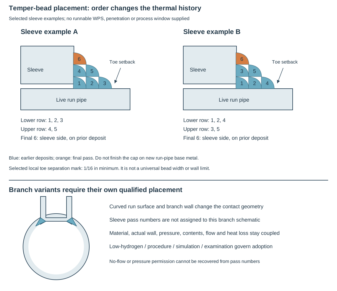
Figure 21.2. Two selected six-pass sleeve examples preserve different numbered placements. They are not one interchangeable recipe. First-layer contact, subsequent buildup and the final sleeve-side pass are shown schematically. Branch attachments require their own qualified pattern rather than transplantation of a sleeve sequence. Structured sequence and conditions.
In the first sleeve example, passes 1, 2 and 3 establish the lower row, progressing away from the sleeve. Passes 4 and 5 build above it, and pass 6 finishes at the sleeve side.
In the second, the lower row is 1, 2 and 4. Passes 3 and 5 occupy the next level. Pass 6 again finishes at the sleeve side. The difference is meaningful. The numbers identify deposition order, not simply the final stack height.
The selected illustrations mark 1/16 in minimum separation at the depicted lower-layer/upper-layer toe region. That local geometric mark belongs to these drawings. It does not supply a universal bead width, electrode travel or penetration limit. The diagram conveys which toe is kept behind the established run-pipe contact boundary, while an executable procedure must define the actual placement and dimensions.
The accompanying branch examples use a different curved run surface and attachment geometry, including different numbers and placements of deposits. The qualified branch sequence must cover its own fusion surfaces, access and thermal response. Reversing a sleeve drawing, changing branch wall or extending a final bead onto previously unwelded run material changes the represented condition. This applies even if the nominal heat-input number stays the same. Record the selected geometry and order with the material, fit-up and live-fluid state. This allows the production welder to reproduce the qualified arrangement and the examiner to locate its critical regions.
The selected historical carbon/low-alloy-steel discussion pairs temper-bead deposition with low-hydrogen electrodes and illustrative 3/32 or 1/8 in electrode diameters. Its attachment chemistry guidance uses IIW carbon equivalent C + Mn/6 + (Cr + Mo + V)/5 + (Ni + Cu)/15. The selected maximum is 0.42 below 0.5 in attachment wall and 0.40 at or above 0.5 in. Where only C and Mn are reported it adds 0.03 for the other elements. These are retained method inputs for that attachment discussion, not a chemistry certificate for the live run or a universal qualified range. Actual run chemistry and wall, pressure, contents, heat removal, preheat/interpass state, process and placement remain necessary inputs to the adopted WPS and simulation/qualification.
Its flow discussion divides walls into very thin 0.172 in and less, thin 0.188–0.250 in, intermediate 0.25–0.500 in, and thick greater than 0.500 in. The printed categories leave a gap between 0.172 and 0.188 in and share the 0.250 in boundary. Do not invent a category for those conditions.
That historical discussion favors maintained flow for very thin wall. It favors reduced or stopped flow for its thin/intermediate cases to reduce cracking. It describes favorable no-flow/pressure conditions outside the very-thin case. Those statements differ from the separately adopted flow procedures, including a procedure that prohibits no-flow welding. They cannot create a hybrid permission to use this bead pattern at unrestricted flow or pressure. Low-hydrogen versus cellulosic penetration, fluid cooling and retained pressure must be evaluated together under the selected route.
The carbon/low-alloy tempering explanation is not a universal material rule. Wet sour service and hydrogen charging keep delayed cracking consequential. Caustic or another service requiring PWHT cannot inherit an online temper-bead substitution, and reactive contents, linings or an unsuitable thermal state can exclude the work.
The selected discussion treats stainless steel differently and does not require temper beads for it. That does not authorize copying a carbon-steel WPS onto stainless. Production control carries placement, cleaning and examination access into the actual deposit sequence. Online wall coverage locates the run material that must be established before any bead is placed.
Retain the thermal chart's initial state and welding geometry
A thermal chart lookup must preserve the initial wall state and the welding geometry represented by its axes. The discussed 25°C and 150°C charts are for carbon/carbon-manganese steel with covered-electrode welding. They distinguish first fillet weld, second fillet weld and bead-on-plate/buttering heat-input scales. The horizontal axis shows actual measured wall thickness together with its squared-thickness scale. Selecting a convenient heat-input axis or reading squared thickness as thickness changes the lookup.
Carry the WPS heat-input calculation into its corresponding chart geometry and read maximum inner-wall temperature and penetration as separate outputs. Retain the chart's collapse/risk regions, transition to three-dimensional heat dissipation and the stated limits on extending the lines. A chart for an initial 25°C wall is not evidence for a wall initially at 150°C. Neither establishes another initial condition by an unqualified interpolation. The structured lookup questions keep the initial state, geometry and quantity references visible.
These charts also show a 4.8-mm reference, and the associated checklist calls for a 4.8-mm minimum. The procedure's body instead states its coupled 5-mm blow-out screen with material, temperature and hoop-stress conditions. Those are not demonstrated equivalent eligibility statements. Retain the existing 5-mm coupled body condition above and the local unresolved 4.8-mm references. Neither rounding downward nor choosing a larger wall alone resolves the full method. Simulation and examination remain the required response under the selected application, rather than a way to disguise an uncertain chart input.
Follow the recovered thermal contours on the chosen weld scale
The paired native maps add the graphical relationships to the thermal lookup path. Their horizontal coordinate is x = t_a², in mm², where t_a is the minimum actual measured run-wall thickness in mm. The vertical plotting coordinate q is the bead-on-plate/buttering heat-input scale in J/mm. At the same plotted height the first-fillet scale reads 1.5q, and the second-fillet scale reads 1.25q. These are scales on the selected graphic, not new efficiencies to apply on top of a WPS heat-input calculation.
For a first-fillet input, use q = HI/1.5. For a second-fillet input, use q = HI/1.25. For bead/buttering, use q = HI. Mixing those scales changes the point being evaluated.
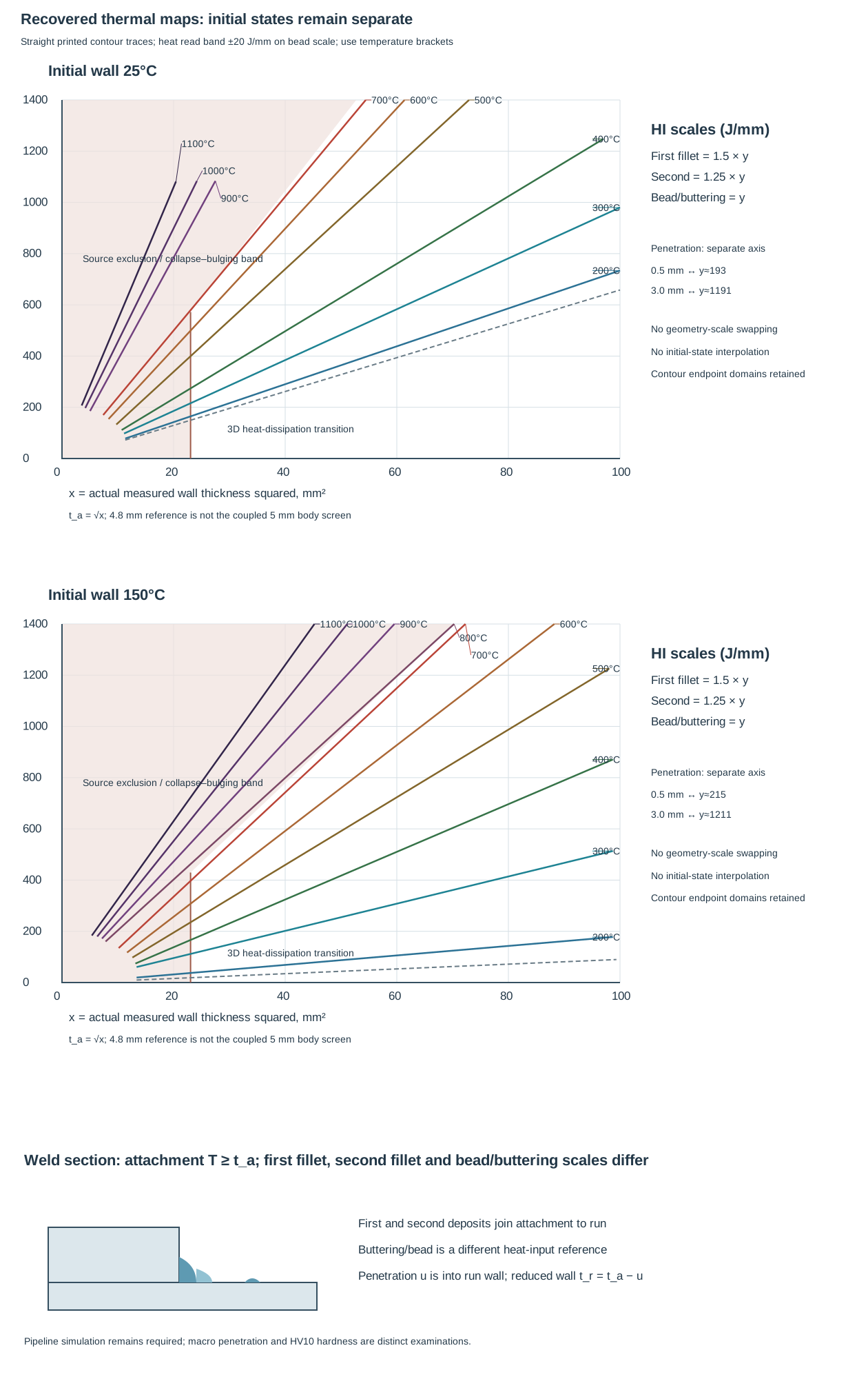
Figure 21.3. Recovered graphical teaching maps for covered-electrode welding of carbon/carbon-manganese steel. Traced contour segments preserve their visible endpoint domains. Heat readings carry a ±20 J/mm band on the bead scale and the squared-thickness coordinate a ±0.7 mm² reading band. These are recovery bands, not permissible WPS variation. Temperature is read as a contour bracket. Structured contours, axes and recovery limits.
The 25°C map retains its printed 200, 300, 400, 500, 600, 700, 900, 1000 and 1100°C contours. Its absence of a labeled 800°C contour is preserved rather than filled with a new acceptance line. The 150°C map retains 200 through 1100°C at its printed 100°C steps. Each line is a maximum inner-wall-temperature relationship for the selected initial state and chart geometry.
The shaded source exclusion/collapse–bulging region and the three-dimensional heat-dissipation transition are separate features. A point below a contour does not erase a source exclusion region or establish a safe pressure. Where the three-dimensional transition applies, the source describes maximum temperature as independent of wall thickness and/or pipe contents. It does not make every thick-wall, high-heat-input condition independent of its other assessment inputs.
Read penetration u, in mm, separately from the right-hand scale corresponding to the selected plotting height. It is not the temperature contour label and is not an additional wall thickness. The pressure evaluation uses t_r = t_a − u, retaining the actual-wall and penetration definitions. The structured recovery binds separate right-axis calibrations to the two initial-state maps. It does not infer a common penetration equation or silently shift one initial state into the other. Recovering that graphical read cannot establish actual weld-pool penetration or the hardness of its HAZ.
For a hypothetical lookup exercise, take an actual-wall teaching input t_a = 8 mm and a first-fillet heat input HI = 750 J/mm. This selects x = 64 mm² and q = 500 J/mm. On the recovered 25°C map that location lies between the 200 and 300°C contours. On the recovered 150°C map it lies between the 300 and 400°C contours. The different brackets demonstrate the initial-state consequence without interpolating a fictitious third initial state.
Reading the separate penetration scales at that height gives a coarse about 1.1–1.4 mm teaching envelope. Thus t_r is approximately 6.6–6.9 mm for the assumed 8-mm wall. The envelope deliberately covers the graphical recovery bands of both separate maps. It does not select a conservative production penetration or approve an operating pressure.
The source permits horizontal extension of lines for increased wall thickness. The saved dataset stops at its traced segment endpoints and does not implement that provision as a universal numeric extrapolator. Any use of the source's local extension still has to preserve the selected state, output, exclusion/transition regions and procedure. No interpolation between initial 25°C and 150°C states is established, and initial wall temperature above 150°C calls for specialist advice. Values beyond the printed heat-input range or absent contour endpoints cannot be supplied by extending a fitted line merely because the visible portion is straight.
The chart/checklist 4.8-mm reference remains unresolved against the procedure's coupled 5-mm body screen. That screen also depends on yield strength, operating temperature and hoop-stress ratio. A line on the chart does not resolve the material's permitted temperature envelope, reactive contents, hydrogen history or live-fluid cooling. Preserve the flow and examination basis and the retained-pressure calculation with the actual WPS values, geometry and measured wall.
The source procedure also limits process pressure during the operation to 7000 kPa gauge, or the equipment maximum if lower. This applies in addition to the calculated welding-pressure limits. The thermal map does not replace these limits.
The required simulation uses an empty pipe with the proposed materials, wall, process, weld configuration, preparation and essential parameters, with inside-surface temperature observations. A marginal or unacceptable preliminary prediction invokes the defined simulation response. Pipeline applications require simulation regardless of the preliminary result. For the critical simulated locations:
- Section them to check penetration and macro condition.
- Assess hardness separately by HV10 under the selected material acceptance basis.
Deposit placement adds the contact/sequence dimension of that representation. The recovered chart is an inspectable preliminary relationship, not a qualified WPS, hardness result or pressure rating.
Determine the pressure permitted during welding on its actual basis
A temperature-derating method reduces the wall available at the weld pool and accounts for its temperature-dependent strength. Its equation is:
In these equations, is the calculated permitted inside-to-exterior pressure difference during welding in MPa. For the illustrated atmospheric-exterior applications, the outputs are internal gauge pressures relative to local atmosphere. Other exterior conditions require their applicable pressure-difference and method/route limits. Absolute internal pressure is not substituted for the illustrated gauge quantity.
is nominal outside run-pipe diameter in mm. is the minimum actual wall established by examination in mm. is the method’s penetration allowance in mm. is reduced wall in mm. is specified minimum yield stress for the off-plot pipeline calculation, or basic allowable stress for the on-plot piping calculation, in N/mm².
is the applicable longitudinal-joint factor, the temperature derating factor and the off-plot design/safety factor. For its off-plot factor the method recommends a maximum of 0.8. For the described on-plot ASME B31.3 basis, that factor is already included in basic allowable stress. It is not applied again as an extra pipeline reduction.
The penetration allowance can come from the selected thermal assessment, or the specifically permitted 3-mm assumption in that method. It is not a measurement of every weld's penetration. The temperature factor uses predicted maximum pipe temperature during welding, rather than normal fluid temperature. Under this adopted table, linear interpolation is permitted between the stated entries:
Table 21.1. Conditional welding-pressure temperature factors.
| Predicted maximum pipe temperature during welding |
Temperature factor |
| Above 675°C |
0.00 |
| 675°C |
0.20 |
| 600°C |
0.35 |
| 500°C |
0.57 |
| 400°C |
0.65 |
| 300°C |
0.75 |
| 200°C |
0.85 |
| 120°C |
0.91 |
| Below 120°C |
1.00 |
These are factors for this specified calculation, not a new material-property table for general design. Structured method data retain their scope and separate quantity definitions.
For off-plot pipelines, that procedure also calculates a pressure from its applicable toughness/crack-propagation method and takes the lower of the two method results. This is an explicit combined requirement within one adopted basis. Its conversion from the applicable toughness-method hoop stress to pressure is:
In this equation, is the corresponding allowable hoop stress in N/mm², and is nominal thickness in mm. remains nominal outside diameter in mm. Pressure follows the stated inside-to-exterior basis in MPa. For the illustrated atmospheric exterior, it is gauge pressure relative to local atmosphere. Fluid, burial and the applicable toughness formulation determine . Nominal thickness here must not silently inherit the reduced-wall definition of the temperature method.
That adopted procedure additionally limits the operation to 7 MPa gauge and to a lower tapping-equipment working rating where applicable, and excludes subatmospheric hot tapping. Those bounds are separate from the two calculated pressures. They remain part of the complete eligibility, process and equipment evaluation.
Obtain the supported toughness-method stress on its stated unit basis
The toughness method answers whether a crack can propagate unstably in the specified pipeline application. That is a different failure question from local weakening and penetration during welding. The discussed historical method distinguishes fluid type and burial. Its supplied equations for gas and two-phase lines differ between buried and aboveground applications. A higher Charpy value does not erase the thermal method or the tapping-equipment limits.
For the buried gas/two-phase relationship:
For the aboveground gas/two-phase relationship:
In these equations, is the specified Charpy toughness in ft·lbf. is nominal outside run-pipe diameter in inches. is nominal wall thickness in inches, and calculated is in ksi. The coefficients and exponents belong to these empirical, unit-bound relationships. They do not remain numerically valid after entering millimeters or joules. Nominal wall here remains distinct from the measured, penetration-reduced wall of the thermal method.
The method calls for minimum average values specified for procurement and confirmed by certificates where possible. These are at minimum pipeline design temperature or lower, using full-size 10×10-mm transverse specimens. It also states a minimum of 10 ft·lbf, approximately 14 J, for its high-vapor-pressure-liquid, buried-gas/two-phase and aboveground-gas/two-phase applications. That rounded equivalence is not permission to enter a joule value directly as .
The separate high-vapor-pressure-liquid formulation is not supplied in this account and depends on its referenced assumptions/graphs. It cannot be recreated from the two gas equations. Its no-additional-requirement statement for specified land water/stabilized-liquid pipelines concerns this particular toughness check, not every pipeline design or hot-tap requirement.
The structured toughness companion retains the equations, method units, rounded 1 ksi = 6.895 N/mm² conversion and hypothetical calculations. Apply the lower thermal/toughness result and separate 7-MPa-gauge/equipment caps; a toughness conversion alone is not an operating permission.
Compare the required methods only within the one adopted off-plot basis, with a consistent pressure reference. These historical equations and teaching inputs do not establish a current fracture-control qualification or accept a pipeline.
Preserve the distinct flow and examination conditions
One adopted online-welding practice prohibits no-flow welding and uses a minimum velocity of 1.3 ft/s. It suggests a maximum liquid velocity of 4.0 ft/s and procedure adaptation for excessive cooling.
Another adopted method permits its assessed no/intermittent-flow case only when the required absence of an explosive/flammable mixture and oxygen ingress is confirmed. Otherwise, it uses its defined purge arrangement. Its suggested maximum liquid velocity is 1.75 m/s, with heat-loss testing and procedure response above that value. Both preserve acceptable interpass temperature. Neither provides an unrestricted gas-flow permission independent of that condition.
A separate historical checklist’s flow-reduction instruction excepts wall at or below 0.188 in. That local statement remains distinct from both adopted flow procedures. The values are not one envelope assembled from the lowest minimum and highest maximum. Choose the applicable procedure and its whole material/fluid/thermal/operating basis. For unstable flare duty, the specified purge, instrumentation and fast warning functions are part of the selected application. A nominal average velocity measured before the job cannot establish continuous conditions through welding and cutting.
Examination also has purpose and timing. Establish actual wall, laminations/defects, ovality and the soundness of relevant nearby welds before attachment. Inspect the qualified attachment as specified during and after welding, including the applicable hardness and delayed-cracking examination. One practice uses a 48-hour delayed examination with defined metallurgical adjustment provisions. Another references its selected weld-inspection procedure. An immediately clean surface examination is not proof that a later hydrogen-assisted crack cannot develop.
The personnel, method and acceptance basis must be appropriate to the material and feature being examined. Magnetic-particle, penetrant, ultrasonic, radiographic and hardness evidence address different questions. Examination develops them. Keep the actual online thermal/process state and any delayed verification with the evidence.
The structured procedure distinctions retain the separately adopted thickness, flow, examination and testing scopes for this comparison.
A hot-tap wall survey is located by the actual tie-in center and proposed weld line. Measuring an accessible point elsewhere on the run does not establish the material beneath a planned attachment. The selected footprint drawing therefore combines a general surface grid with a separate series of measurements around the attachment weld line. Keep the coordinates of the proposed center and weld footprint recoverable after cleaning, surveying and fitting placement. Moving the attachment after examination can move the weld onto material that was never examined.
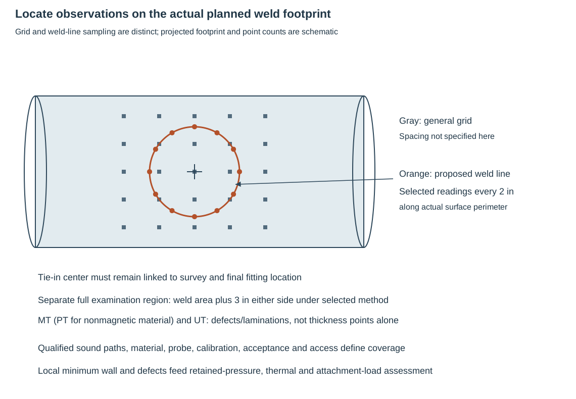
Figure 21.4. Selected measurement-location example: readings every 2 in along the weld line. The general grid spacing is undimensioned. Drawn point count and projected circular appearance do not establish actual circumference, complete scan coverage or acceptance. Structured footprint and coverage distinctions.
The grid supports a spatial picture of actual thickness and local variation. The weld-line observations address the perimeter where the attachment will transfer heat and load. The 2 in instruction applies along that actual weld line on the pipe surface, not to every horizontal or vertical grid interval in the sketch. A projected circle on a curved run is not a dimensioned flat template. Establish the actual attachment perimeter and survey coordinates under the adopted method rather than scaling this illustration to obtain a count or a physical diameter.
A companion preweld requirement fully examines the weld area plus 3 in on either side. It uses magnetic-particle examination, or penetrant for nonmagnetic material, and UT to locate defects and laminations. That region is a separate examination obligation. The 3 in width is not the weld-line sampling pitch. Thickness readings alone cannot demonstrate the required lamination search or sound path through the intended volume.
A local checklist’s 3-in seam-distance question remains subject to its body’s exception/review route; it cannot override another method’s weld-separation rules. Probe, coupling, material, surface, curvature, calibration, coverage and acceptance criteria must suit the feature being assessed. Examination evidence distinguishes these questions from a generic “UT complete” entry.
Record the evaluated minimum wall and local anomalies in the proposed weld/load region, together with pipe ovality, existing weld locations and relevant flaws or laminations. Use those actual conditions in the retained-pressure/thermal assessment and in the attachment and machine load evaluation. The welding condition reduces effective strength and can consume part of the load-carrying thickness. One original nominal schedule or an average of grid readings is not the wall remaining beneath the critical bead. A relocation, different fitting footprint or changed support position reopens the affected coverage and design inputs.
The selected route also requires pre-machine visual inspection, root/cap surface examination, weld/HAZ hardness and normally 48-hour delayed examination with its defined metallurgical adjustment. The surveyed footprint does not replace those stage/access requirements. Temper-bead placement connects the surveyed material to the actual thermally affected region.
Make the attachment, valve and machine one evaluated configuration
A branch removes part of the run wall when drilled. Reinforcement and remaining pressure strength must cover that changed geometry. A conventional area-replacement method can be appropriate within its application. A highly stressed pipeline with a large branch ratio may require a more rigorous local assessment. Pressure adequacy also does not establish that the run pipe carries the valve and tapping-machine loads acceptably.
Cantilever weight can bend the run pipe or buckle the local wall at the branch. An off-vertical machine can also twist it. Provide the evaluated support and clear working space in the actual drilling position. One design procedure applies a factor of 2 to its calculated tapping-load stress contribution before combination with pressure stress. This is a specified assessment allowance, not a prediction that the machine physically doubles in weight or a universal dynamic factor for every pipe load.
For a connection procedure specifically adopting the following reduced-fitting limits, retain both size and ratio conditions:
Table 21.2. Conditional reduced-fitting size and diameter-ratio limits.
| Application |
Maximum branch size |
Maximum branch/run diameter ratio under this method |
| On-plot piping |
DN 75 |
1/3 |
| Off-plot pipeline |
DN 50 |
1/4 |
Its reduced-fitting minimum is DN 25 and these fittings are excluded where vibration is expected. Retain the method's diameter convention. The ratios do not define an internal-area calculation.
Reinforced set-on branches and full-encirclement sleeves form other choices. A preformed split tee can serve a stopple or a connection arranged for subsequent pig passage. Its annular gap can introduce a fluid-dependent corrosion issue. These alternatives have different joining, test and local stress conditions. A full-bore valve must allow the actual cutter to pass and close after retraction. Nominal branch size alone does not prove that clearance.
Location affects both loading and debris. A downward-oriented tapping configuration on a horizontal line can simplify support and reduce the tendency to retain swarf near the isolating valve. Existing welds, deposits, local corrosion and pipe ovality also constrain the site. The selected weld-separation/attachment rules must be retained with the adopted procedure rather than borrow one clearance dimension from another basis. Upstream sensitive equipment needs the specified swarf protection or another evaluated means.
A cut coupon can spring or jam, especially in some large or spiral-welded pipes. A selected reinforcement/retention arrangement must preserve the cutter/retraction and valve-closing functions. The branch opening can be smaller than its nominal internal bore, and a retained plug or later pig operation imposes other geometry. Branches and pipeline/pigging interfaces carry those relationships beyond the original cutting task.
Separate the maintained service path from the section being removed
A temporary bypass and two plugging sites can create an alternative topology for local pipe replacement without losing the intended service path. The bypass joins the live upstream side to the live downstream side outside the section bounded by the plugging locations. The old section between them is the work section. It is not the bypass. Lying between two drawn plugs does not establish that it is an isolated pressure volume.
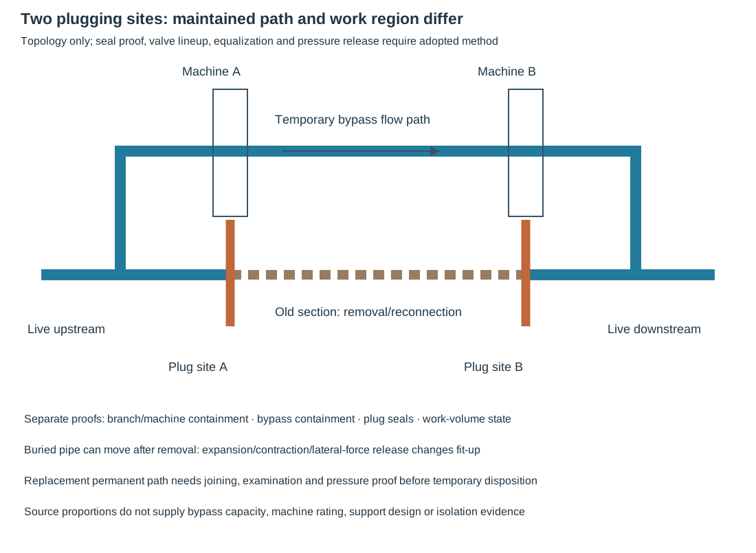
Figure 21.5. Authored topology based on the selected two-machine arrangement. Solid blue is the intended maintained path. Orange boundaries identify plugging sites. The dashed old section is the removal/reconnection work region. No valve lineup, seal proof, pressure equalization sequence, bypass size or machine capacity is inferred from the drawing. Structured boundary questions and restoration states.
The topology creates several simultaneous pressure-boundary questions:
- Containment at each installed branch/plugging machine
- The temporary bypass itself
- Each plug-to-run interface
- The work section’s actual isolated/depressurized state
Their proofs are different. A passing attachment pressure test does not establish plugging seal performance. Observed bypass flow does not establish zero pressure or no ingress in the removed section. The adopted supplier/project method defines seal verification, leakage response, monitoring, pressure equalization and safe release. The figure supplies locations for those questions rather than answering them with generic actions.
Service continuity also needs an evaluated bypass path. Its inputs include actual fluid, pressure/temperature, required flow, allowable pressure loss, temporary component ratings, supports and load cases. The plugging-machine and bypass connections must remain compatible with the live run during installation, use and removal. A nominally available route can still fail its capacity, thermal, access or support requirement. Connection and machine loads apply to the actual bypass and plugging configuration. No bypass sizing follows from line proportions in this sketch.
Removing a buried section can release expansion, contraction or lateral forces and move the cut ends. The replacement needs actual released terminal positions, support/restraint assumptions and joining allowances. Unplanned pull-up through the new spool or bolting can retain stress; pipeline modification and fabrication datums govern the changed fit.
The restored path has new joints, pressure boundaries and possible permanent plugs/branches. Its joining, pressure proof, coating/cathodic protection and support state must suit that permanent configuration before removing temporary bypass/machine supports under the selected method.
Separate the wetted branch from its reinforcement and enclosure
The three selected branch alternatives change which surfaces contain fluid and which welds supply reinforcement. A reduced branch fitting creates its outlet locally on the run. A reinforced set-on branch has its own run-to-branch pressure connection, with a surrounding sleeve providing reinforcement. In the selected set-on illustration fluid does not contact the reinforcing sleeve, and the branch flange is omitted from that view.
A preformed split tee instead supplies its own outlet and encircling shell with longitudinal joining. After perforation, its annular space can communicate with the process. A dry reinforcement assumption cannot be transferred from the set-on sleeve to every encircling attachment.

Figure 21.6. Reduced fitting, reinforced set-on with dry sleeve, and preformed split tee with annular interface. This is a qualitative contact/load comparison, not reinforcement sizing. Flange omission in the set-on view does not eliminate its valve/machine interface. Structured functions and conditions.
The reduced-fitting size/ratio limits jointly define that selected category. A larger reinforced set-on branch has its own assessment; this route prefers a full-encirclement sleeve over a pad/saddle and requires at least one nominal size below the run, except its selected stopple case. The cut opening remains smaller than branch ID.
A split tee designed for full pipeline pressure can provide plug/pigging or full-bore stopple interfaces in this selected connection method. Its small annular gap introduces a corrosion question for some fluids. A different adopted method excludes its split-tee route in corrosive/steam service where crevice corrosion is accelerated. It normally treats the fitting as temporary, with replacement and regulatory routing. It separately permits consideration of permanence for non-expansible-fluid systems under its consultation requirements.
These eligibility and permanence bases remain distinct. The three-interface drawing cannot override either. Keep component material, sour-service suitability, longitudinal/end-weld function and required examination/test sequence with the selected route.
The machine-load assessment remains separate from pressure strength and must match actual orientation, branch height, working space and subsequent piping loads.
Fit the cutting and retraction states through the same valve
The drilling machine, isolating valve and branch form a stack whose geometry must work in all three states below. The machine drives a boring bar, pilot and cutter through the open valve and branch toward the live run wall. The opening establishes a new live fluid path. The cutter and retained coupon must then retract far enough to clear the valve's moving closure member. Only after verified retraction can the valve close and isolate the machine-side volume for controlled pressure release and removal.
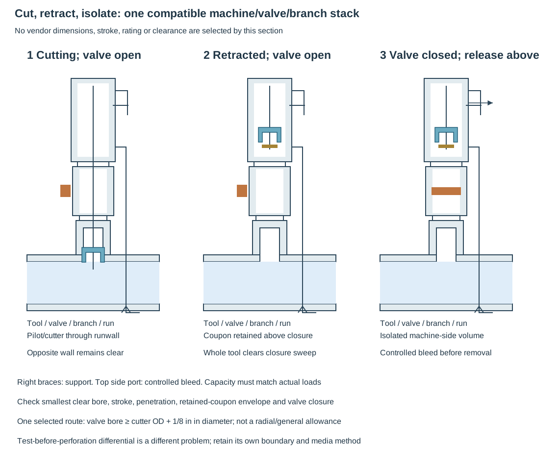
Figure 21.7. Conceptual three-state section. Cutter travel, coupon envelope, branch length, opposite-wall clearance, valve closure and machine support require equipment-specific dimensions and loads. The schematic supplies no stroke, rating or clearance measurement. Structured state and interface checks.
Check the actual smallest clear bore through valve, flange/adaptor and branch against the cutter and retained-coupon envelope. In one selected inspection route, the valve has a clear full round opening at least 1/8 in greater in diameter than the specified cutter/drill OD. That is a diametral condition for its route, not a radial allowance or a general clearance for every cutter. Bore alone does not establish adequate stroke. The stack height and branch length must permit the intended penetration and full withdrawal. A short branch reduces leverage, yet it must still accommodate the selected cutter/pilot travel and a place for the coupon above the valve closure envelope.
Establish the cutting depth against the actual run geometry so that the pilot and cutter do not strike the opposite wall. The coupon can spring or jam, particularly in some large or spiral-welded pipe. Where selected, its reinforcement device is installed before the connection hides the run surface. Retention, cutter compatibility and the retrieval envelope remain part of the machine method. A successful pilot penetration is not completed coupon retrieval, and a retrieved coupon is not evidence that the finished valve can isolate. Swarf protection and downstream equipment/pigging consequences belong with the evaluated cutting and contingency plan.
The machine pressure boundary includes its seals, packing and adaptation to the valve. Ratings and compatibility must match the actual pressure, temperature and contents. A historical illustrative machine arrangement provides no manufacturer stroke or rating.
The external bleed/drain connection addresses the isolated machine-side volume after the valve is closed. Verify the actual isolated state and controlled release under the manufacturer's method before removing flange bolts. A vent reading alone does not establish that every trapped pocket has drained, especially where hot liquid remains above a closure member. The test boundary and media sequence remains a separate preperforation problem. Pressure testing against an intact run wall is not a demonstration of cutter travel or valve-closing clearance.
Test the added boundary without collapsing the live run pipe
Before perforation, the branch/fitting test can pressurize the outside of the still-intact run wall. The external differential can govern buckling even when the new branch itself is strong enough. A higher test pressure is therefore not automatically a more useful verification.
A split-tee test procedure using the stated external-pressure basis uses:
In this equation, is the fitting/branch test pressure. is actual operating pressure inside the run pipe during the test. is the established allowable external differential for that run-pipe configuration. Use consistent pressure units and reference. The allowable differential needs the applicable external-pressure calculation, such as the specified ASME VIII Division 1 UG-28 route under the adopted method. It is not supplied by the branch pressure class.
If the actual run pressure changes while test pressure remains held, the differential changes too. With hypothetical MPa and an independently assumed allowable differential of 0.4 MPa, the relation gives MPa. If falls to 1.7 MPa without changing the test, the external differential becomes 0.7 MPa, exceeding that assumed allowance. This demonstrates why operating-pressure control/observation and the contingency belong to the test basis. It establishes no actual pipe's buckling capacity. The applicable branch/code test ceiling also remains a separate limit.

Figure 21.8. Authored pressure-condition schematic, not a split-tee design detail. Test pressure acts outside the intact run wall while process pressure acts inside. Their difference must stay within the evaluated run-pipe allowance. Structured method data preserve the illustrative values and distinct bounds.
A set-on branch uses a different local buckling/test method. Its graph-based assessment uses actual operating stress relative to specified minimum yield, outside run/branch diameters and actual run wall. The stated graph simplification assumes equal branch and run thickness. It is described as conservative for buckling in the normal case where the branch wall is thinner.
Where that assumption or conservative condition does not hold, use the specified alternate formula rather than the graph. Its test pressure may not exceed the branch design-code test pressure. Do not use a split-tee differential allowance as a universal set-on value or apply the graph's pipeline stress-ratio convention without its defined scope.
Read the set-on test ratio from its actual geometry and stress family
For the discussed set-on chart method, choose the family from actual operating hoop stress and the material's specified minimum yield stress. This is an operating stress ratio. It is not automatically the pipeline's selected design factor. Use actual run diameter/wall ratio to select the curve, and branch/run outside-diameter ratio for the horizontal coordinate. The vertical read is . Each ratio is dimensionless, but its diameter, thickness and pressure quantities must still share the stated measurement/reference basis.
As a hypothetical coordinate example, let mm, mm, mm and N/mm². Assume operating pressure MPa on the atmospheric-exterior gauge basis. A simple hoop input is 147 N/mm², so , and .
The displayed curve read is about 0.55. This teaching comparison retains a coarse 0.50–0.60 read band rather than imply more precision than the plotted observation. Multiplying by the assumed gives approximately 3.23 MPa, with a 2.94–3.53-MPa teaching band. These are graph-reading arithmetic, not a test-pressure approval or a derived buckling capacity.
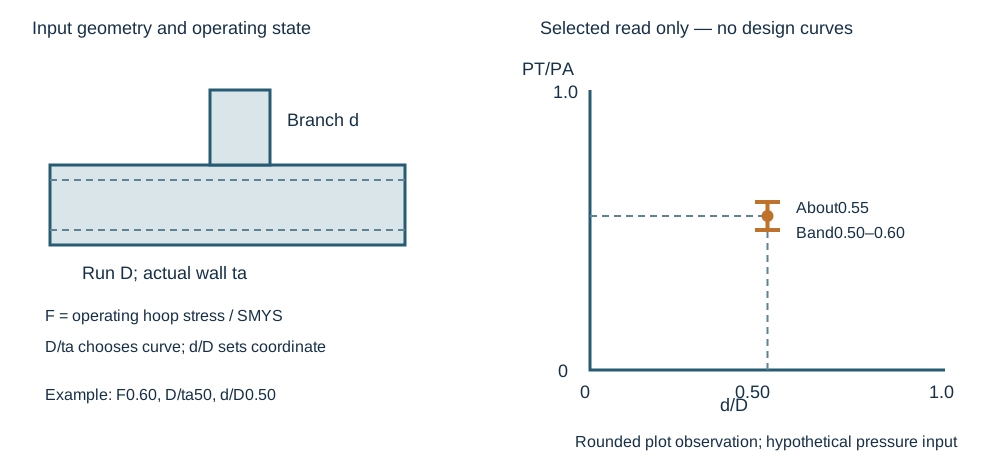
Figure 21.9. Authored lookup schematic and selected rounded plot observation. The marked band illustrates the stated , , read. It is not a reconstruction of complete design curves or a new accuracy criterion. Structured lookup geometry and data retain the hypothetical inputs, read band and eligibility limits.
The chart's equal branch/run-wall assumption and stated conservatism for a thinner branch remain necessary. A thicker branch or an unrepresented configuration requires the applicable alternate method, whose underlying formulas are not supplied here. The source also gives specific conservative uses at lower on-plot stress ratios and smaller diameter ratios. Those bounded provisions do not create a general extrapolation rule. Finally compare the result with the branch design-code test ceiling, the evaluated welding/process condition and equipment limits. The split-tee relation answers a different configured test problem and cannot replace this lookup.
The two-panel recreation adds the missing plotted domain beyond the single set-on teaching observation. The upper panel contains F = 0.60 and 1.00. The lower contains F = 0.50 and 0.72. Each family contains D/t_a = 30, 50, 80 and 120, with its own line style.
Here F is actual operating hoop stress divided by SMYS. D is run outside diameter, t_a is actual run wall, and d is branch outside diameter. The horizontal ratio d/D and vertical ratio P_T/P_A use those actual references. F must not be silently replaced by the safety/design factor used in a different welding-pressure equation.
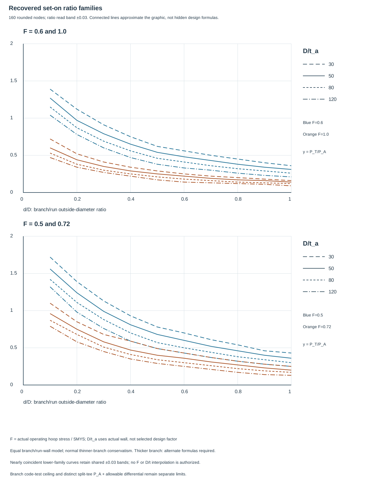
Figure 21.10. Graphical teaching recovery of sixteen configured curves over d/D = 0.10–1.00. Rounded node readings carry a ±0.03 ratio band and ±0.012 horizontal-coordinate band. These bands describe recovery from the graphic, not engineering scatter or a pressure-test acceptance margin. Connecting nodes supplies a graphical approximation. It does not introduce an approved interpolation rule between stress or wall families. Structured curve nodes and limits.
Choose a represented F and D/t_a pair before moving along d/D. Increasing the branch/run diameter ratio reduces the plotted test-pressure ratio in each recovered series. Changing the wall ratio or operating-stress family changes the result at the same branch ratio. A visually nearby curve is not a substitute for a missing configuration.
The source’s actual legends govern the recovery. Conflicting historical captions that name an F = 0.8 family or D/t = 60 are not data for these panels. The saved curves retain their actual displayed families and do not construct those absent curves.
For a hypothetical comparative read, take d/D = 0.50 and D/t_a = 50. The recovered ratios are approximately:
- 0.68 at F = 0.50
- 0.54 at F = 0.60
- 0.40 at F = 0.72
- 0.25 at F = 1.00
Each has its ±0.03 graphical band. These are separate configured observations rather than one pipe whose pressure or material is assumed to satisfy all four cases. They expose how selecting the wrong family can materially change the proposed branch test pressure.
For the particular hypothetical F = 0.60 case already developed above, P_A = 5.88 MPa. The recovered 0.54 band 0.51–0.57 would give P_T approximately 3.18 MPa, with a 3.00–3.35 MPa graphical band. This narrower recovery band is not a replacement for the earlier deliberately coarse 0.50–0.60 teaching band. Both express an approximate observation rather than an accuracy certification. The product P_T = (P_T/P_A) × P_A keeps actual run pressure visible, but the arithmetic alone does not establish an allowable test pressure.
Near larger d/D, some lower-panel lines nearly coincide. In particular, the F = 0.50, D/t_a = 120 curve and F = 0.72, D/t_a = 30 curve occupy shared graphical read bands. Their saved rounded centers can agree while their configuration identities remain separate. That agreement is not evidence that the underlying models or configurations are identical. The recovery does not invent separated numerical values below the resolution of the plotted lines, and it does not infer their generating formulas.
The model assumes equal branch and run walls and is stated to be conservative against buckling for the normal thinner-branch case. A thicker branch requires the selected alternate formulas from the underlying report. Those formulas are not supplied by this recreation. The particular on-plot use of F = 0.50 for a lower actual stress ratio, and conservative use for d/D below 0.10, remain source-specific provisions. The saved domain begins at 0.10 and does not convert either into a general extrapolation rule. Compare any selected result with the branch design-code test ceiling, actual test-state run pressure, attachment and equipment limits, temperature/media conditions and the adopted approval route.
This is the set-on branch-before-perforation test problem, where a still-intact run-wall patch lies beneath the branch test pressure. The dry reinforcing sleeve interface must not be confused with a split tee enclosing an annulus. The split-tee method uses P_T = P_A + ΔP_allow, where ΔP_allow comes from its separately evaluated run-wall external-pressure/buckling assessment. Its fluid contact, test medium and external differential are different configured questions. Preserve the existing test-boundary explanation and test sequence/media. No set-on ratio curve supplies a split-tee buckling calculation, a machine leak-test requirement or a permissible welding flow state.
Verify each seal and test state under its own conditions
One adopted sequence distinguishes three tests before cutting:
- Leak testing the hot-tap valve, preferably separately so the correct seal is evaluated
- Testing the completed branch with the valve installed/open for strength and leak tightness
- Leak testing the mounted drilling machine with the valve closed
Its stated minimum durations are five, thirty and five minutes, respectively. Valve/machine leak tests use the highest run pressure that could occur during the operation. Branch test pressure follows its separate calculated basis. Passing one test does not establish all three seals or states.
Select media from the governing procedure, surface temperature, contamination and stored-energy conditions. One method prefers water where practical and considers a compatible alternative to avoid water in a split-tee annulus. It excludes gas testing above 7 bar gauge unless its risks and mitigation are fully assessed. Another limits its hydrostatic branch test to skin temperature of 93°C. It specifies nitrogen or helium above that condition, with its own staged pressure/stabilization and protection requirements. These are separately adopted methods, not a combined universal temperature/pressure permission.
Before perforation, the intact live wall gives the branch test a different load, temperature and external differential from the open service connection. Limits on run-pressure change remain part of the test. See testing and restoration.
Carry the evaluated conditions through cutting and special applications
Cutter/coupon retention, machine stroke and valve-closing clearance must remain compatible under the actual process conditions. Leakage, a stuck coupon or lost process control requires the selected contingency/isolation arrangement. Downstream debris protection must be available during cutting.
After the opening is made, the branch becomes part of the live system. The valve and remaining connection must carry the service and loads assigned to them when the machine is removed. Reinstatement and examination must establish that actual end configuration, including any plug, temporary valve removal or later branch piping. Under the specifically adopted completion procedure, the branch is blanked off immediately after removal of the drilling machine. The required coating, site and cathodic-protection condition is restored.
Retain the cut coupon as applicable for evidence of local internal pipe condition. This removed wall piece is different from a corrosion-monitoring coupon. A lost cut coupon is a changed condition requiring evaluation of downstream damage and pigging, not a completed retrieval. A successful coupon retrieval does not establish all the resulting connection functions.
Tank hot work is a distinct application. Liquid level, vapor-space ignition, plate strength/thickness/carbon content, impact/heat-treatment history and the selected nozzle geometry matter. One specifically adopted tank procedure requires at least 1 m liquid head above the hot-work region. Another specifies 3 ft. Within the particular 1-m-head procedure, ordinary tank welding is limited to mild-steel shell plates with these conditions:
- Yield strength not above 240 N/mm²
- Maximum 12.5-mm thickness
- Carbon content below 0.23%
Other steel needs its specifically accepted basis.
Its heat-treated major-nozzle plates are excluded, and the required simulation hardness/impact work must use identical material with the same thermo-mechanical history. The differing head figures do not erase these material, operating and test conditions. Pumping, heating-coil operation and roof/above-liquid hot work restrictions remain with the selected procedure. A pipe-wall qualification cannot be transferred automatically to a heat-treated tank plate or pressure-vessel nozzle.
Pressure vessels and miscellaneous cast/fabricated equipment also have different geometry and manufacturing concerns. The illustrated pipe hot-tap methods discourage or exclude such applications within their own scope. Flare lines combine uncertain/intermittent flow with changing mixture and disposal duties. The selected purge and fast warning arrangement must be established, not inferred from ordinary gas-line velocity. Equipment and service hazards supply the additional physical context.
Retain the repair's technical intent through return and removal
Return to service must establish the intended containment, isolation, loading, cleanliness and protective functions of the resulting configuration. Remove or retain temporary items according to that evaluated state, not a generic rule that all temporary steel disappears. A strongback needed for joint retention, an inspection access or a temporary sealant-heating arrangement can remain consequential through the repair life. Its continued presence and operating constraints must be visible to later operators and maintainers.
A temporary repair retains its evaluated deterioration/life, enclosure/wrap function, exposure/temperature limits, monitoring access and end disposition. Reinjection, retorque, changed duty or unexpected damage can invalidate that basis.
A permanent changed design also needs the affected neighboring assumptions re-evaluated. Added branch mass, new isolation inventory, revised flow, a changed restraint or another material/lining can alter equipment reactions, protection, cleaning and inspection. Continuing integrity and technical continuity connect these effects through the operating life. The useful endpoint is the demonstrated system configuration and its maintained service basis, with an inspectable route to the next intervention.