Chapter 7 — Branches, small-bore connections, vents and drains
An opening and an attachment occupy the same place
Evaluate both pressure reinforcement of the opening and loads carried by the branch, weld/thread and local parent wall. A pressure-chart selection does not establish capacity for valve/instrument weight, piping displacement or vibration.
The evaluated assembly includes nipples, valves, plugs/blinds, tubing, instruments and discharge piping in normal, startup, test, cleaning and maintenance states. Longer insulation extensions, added valves, stationary instrument leads, temporary hoses, braces and partly dismantled configurations change mass, lever arms, stiffness or imposed displacement even when nominal size and pressure class remain unchanged.
Choose the branch geometry with its load and fabrication path
A reducing tee and a straight tee with reducer achieve the size change through different geometry and joints. Manufactured branch fittings provide controlled geometry and inspection access, but mass, cost, availability and joint arrangement can favor another eligible construction.
Integrally reinforced outlet fittings place added material around the branch opening as part of the fitting. Butt-welded, socket-welded and threaded outlet forms lead into different joint and small-bore arrangements. A fabricated stub-in connects branch pipe into an opening in the run, with or without a reinforcing pad or saddle where permitted. The opening, branch angle, wall, weld geometry and reinforcing material need the applicable pressure calculation or qualified detail. Reinforcement is not established merely by seeing a pad around the connection.
An adopted branch chart can coordinate the permitted detail with run size, branch size and piping class. Read its notes as part of the chart. One class procedure may prefer tees for particular size combinations. It may permit a stub-in only for defined low-pressure services with a separate reinforcement check and authorization. Another may supply different outlet details.
These are applicable alternatives under their respective class and service bases. An apparently more compact branch is not interchangeable without checking the conditions that selected it.
External loads must follow the actual geometry. A welded outlet carries branch bending into a local region of the parent pipe. The parent wall and attachment can experience stresses different from those of the branch cross-section alone. A pad intended for pressure reinforcement does not by itself establish capacity for every applied moment. The evaluation must include sustained weight, imposed displacement and dynamic effects where relevant, with the weld and local pipe wall considered.
Fabrication and inspection can reverse an economical choice. Access for a sound attachment weld, required examination, cleaning of crevices and later inspection of the vulnerable detail affect long-term integrity. A manufactured fitting can simplify welding and inspection. It can be preferable when the workmanship and inspection demands of a nominally cheaper fabricated connection are difficult to meet.
Welding and examination supplies the fabrication assurance, while Mechanical analysis supplies the load evaluation. Nozzle cutback and dimensional closure connects a selected fabricated construction to its actual bore, parent outside surface and terminal datums. That scalar geometry establishes a length reference. It does not supply the complete branch profile, reinforcement or welding qualification.
Threaded and socket-welded branches deserve their local restrictions. Thread roots and weld toes can concentrate cyclic stress. Joint geometry can retain fluid or contaminants. A class that excludes a threaded outlet in cyclic service cannot be satisfied by selecting a thicker nipple of the same nominal size. Material, joint type, geometry and loading must be evaluated together. Pressure-retaining joints develops those joint mechanisms.
Geometry restrictions work together
A preference for an outlet fitting is meaningful only within its construction and service conditions. New construction can permit an inline tee before the run is assembled. An existing line that can be isolated can still use an inline butt-welded tee or reducing tee. This requires a different intervention from attaching an outlet to the existing run. A selection list that also describes hot-tap branches does not authorize live work. Intervention must establish that work's process, material, containment and execution basis.
Consider one specifically adopted outlet-selection basis for conventional and insert-type outlets. It distinguishes duplex from non-duplex lines and applies the following conditions together. These are local eligibility restrictions for that basis, not universal limits on branch fittings.
Table 7.1. Conditions in the selected outlet method. Structured conditions and examples.
| Question |
Condition in this adopted method |
What must remain distinct |
| Is the run sufficiently thick for this outlet route? |
Actual run outside diameter divided by wall thickness, , is less than 60 for every duplex outlet and for non-duplex branches of NPS 4 and larger. A separate minimum-wall criterion also applies |
Measured or specified actual dimensions, rather than nominal size. The separate minimum wall is not supplied here |
| Is the branch too large relative to the run? |
Branch nominal size is no greater than 40% of run nominal size |
A ratio of nominal designations, rather than the actual calculation |
| Does the material family permit this outlet size? |
The weld-on outlet size is limited to NPS 12 on non-duplex lines and NPS 3 on duplex lines |
The material family and outlet construction remain attached to the size limit |
| Does the duplex geometry require another strengthening route? |
For duplex or a branch above NPS 3, the basis calls for reinforcing saddles. Full-encirclement arrangements and outlet-neck extensions supply additional strengthening where required |
Strengthening/stiffening is still evaluated, rather than inferred from the alternative's name |
The strict less-than condition and the greater-than alternative leave the exact boundary unresolved in this selection basis. Do not fill that gap by treating equality as permission. Nor can this table replace the separately required minimum-wall criterion, pressure reinforcement or evaluation of external loads. A small non-duplex branch below NPS 4 should not silently acquire the duplex wall-ratio rule, although its other restrictions and mechanical checks still apply.
Service also changes the alternatives. Under this same preference basis, certain split-tee arrangements are restricted to noncorrosive service. An isolated inline replacement and an attachment retained on the existing run have different fabrication and containment consequences. Preserve those conditions when comparing cost, shutdown duration, weld access and later examination. The useful choice is an eligible construction with an evaluated load path and intervention route. Meeting a nominal size ratio alone does not establish that choice.
A process branch has to carry its required flow as well as attach safely. A nominal branch/run percentage describes the selected geometry. It does not calculate throughput, pressure loss or retained phases. Establish the branch's actual flow duty and internal area. Include the states in which it is intermittent, bypassed or partly blocked. A pipe's outside diameter and its nominal designation are different inputs from the area open to flow.
A homogeneous mixture model makes a useful preliminary account when liquid and gas are represented as moving together without slip. At the specified local pressure, temperature and composition, let and be liquid and gas mass rates, and and their respective densities. The modeled volume rate and mixture density are
For mass rates in lbm/h, densities in lbm/ft³ and internal area in ft², is in ft³/h and the common modeled velocity is
The factor 3600 converts hours to seconds. The density follows the volume carried by both phases. Averaging their densities according to mass fraction would give a different quantity. The subscript identifies this homogeneous model, rather than a measured local holdup or the separate phase velocities of an actual line.
One adopted two-phase sizing screen uses the quantity with a limit of 10,000 in its specified customary units. With lbm/ft³ and ft/s, that quantity has units lbm/(ft·s²). It is not a dimensionless index or a pressure in psi. The screen does not calculate pressure loss, actual phase distribution, solids erosion, transient slug force or fatigue/mechanical acceptance. Structured calculation basis.
A density at another pressure or temperature changes the volume account. Phase slip changes the relationship between flow fractions and local holdup. Use a suitable hydraulic method for the actual service, then carry its relevant states and forces into the attachment evaluation. Phase-sensitive equipment piping and Pipeline inventories and slugging develop those consequences at their system interfaces.
Small bore can carry a large mechanical demand
The mass of a valve or instrument matters relative to the stiffness and length of its connecting nipple. A longer cantilever places that mass farther from the root and lowers its stiffness. A heavy valve on a short, thick connection can behave differently from the same valve on a longer nipple. Concentrated mass is not equivalent to a uniformly distributed pipe weight.
Vibration adds an inertial force to that static demand. The parent pipe’s motion can excite the attached assembly, particularly when the forcing frequency approaches one of its natural frequencies. A small observed displacement of the main pipe does not establish a small local stress at the branch root. The attachment can amplify motion, and thread grooves, weld toes or abrupt section changes can concentrate the resulting cyclic stress. Fatigue depends on local stress cycles and the material/detail environment, rather than on how impressive the visible motion looks.
Machinery excitation, reciprocating flow, valve instability, cavitation and two-phase flow can all provide forcing, with different predictability. A particular pump speed does not set a universal design frequency for every root valve. The useful approach identifies likely excitation and evaluates the attachment’s response. Where forcing cannot be reliably predicted, it includes observation of the actual operating condition. Vibration develops the system mechanisms and investigation.
Shortening an unsupported nipple or reducing valve mass can improve its response, but it must still provide the required connection, insulation clearance and access. An added support or brace changes stiffness and the load path. It may reduce local vibration and also oppose the main line’s thermal movement if connected to stationary steel. Select the directions restrained and the relative movement permitted. Do not cure one problem by imposing an unexplained second one. Supports and restraints develops that installed arrangement.
Two serial valves, an added fitting or a changed actuator can make an apparently familiar detail a different appurtenance. The assembly’s mass distribution and moment arms should be reevaluated. If the connection is sufficiently stiff, measured accelerations of the attached masses can provide a useful route to estimating cyclic bending at its base. The method below illustrates that route. It does not replace the parent-pipe local check or a modal analysis when flexibility is important.
A lumped-mass check explains what must be measured
For a stiff appurtenance represented by discrete masses, the inertial force in one selected direction is
and the moment about the selected base section is
In this equation, is the mass of item and is its acceleration in the selected bending direction. The variable is the corresponding perpendicular moment arm to the section. With kilograms, meters per second squared and meters, force is in newtons and moment in newton meters. Use mass, not a force labeled as weight. If an input is a weight force, divide it by the appropriate gravitational acceleration to obtain mass in a consistent unit system.
For a sinusoidal evaluation, accelerations and moment must be treated with their relative signs and phases. The sum of individual amplitude magnitudes is a conservative bound on the magnitude of their combined moment in this model. It is not automatically the measured amplitude when the masses move out of phase. The selected direction also matters: the same assembly can respond differently in perpendicular directions.
A bending-stress estimate for the selected section is
In these equations, is bending-moment amplitude and is the elastic section modulus of an annular section. The variables and are its outside and inside diameters. The variable is the applicable geometric stress-concentration factor for the evaluated detail. is dimensionless; has units of length cubed. With moment in N·m and in m³, stress is in pascals. The formula models elastic bending of the chosen section.
The appropriate local-detail factor and fatigue basis are separate inputs, and the parent pipe at the attachment still needs its own local stress evaluation.
Associate acceleration with direction, location, phase and operating state. Stress range is twice amplitude only for a symmetric fully reversed cycle; compare like quantities under the actual fatigue criterion.
Locate the masses and the section before assigning moment arms
Figure 7.1 connects a two-valve assembly to the rigid-appurtenance model. The connection has two 18-lbf valves on short intervening nipples. The model replaces each valve by a mass at its center of mass. Bending demand is to be evaluated at the selected base section A. That section is not the valve-body edge or parent-pipe centerline.
In the illustrated model the nearer center is 2 + 5.5 = 7.5 in from A. The farther center is another 6.5 in away, giving 14.0 in. These are the exemplar's model distances.

Figure 7.1. A conceptual physical assembly and its paired lumped-mass model. The model carries centers, base section and distance chain explicitly. For acceleration along Y, perpendicular to the model's center-to-base line in this plane, the displayed distances are the perpendicular arms. Valve shapes are schematic. The model distances are not fabrication dimensions. Structured geometry and unit data preserve the association.
A weight of 18 lbf gives lbf·s²/in under the exemplar's gravity convention of 386 in/s². With and in in/s², the signed moment in lbf·in is therefore
Division by gravity is essential: multiplying a weight by gravity would not produce mass or these coefficients. Acceleration may instead be reported as a multiple of . Then the numerical force is lbf and the coefficient convention changes. State the acceleration unit before using either expression. The label “18-lb mass” by itself does not establish a consistent force calculation.
The arm is selected from geometry and force direction. In vector form , where each points from A to a center of mass. For collinear centers at distance and acceleration making angle with that line, the bending arm is . It equals in the illustrated perpendicular direction and becomes zero for acceleration along the line in this idealization. The latter case still produces axial inertial force.
Out-of-plane acceleration produces bending about a different axis. Actual off-axis centers can also produce torsion. Preserve those distinctions instead of using the branch length for every measured direction.
Combine signed accelerations with their relative phases; an opposite-phase response is not the sum of magnitudes. The rigid approximation must remain plausible. Significant relative deformation requires modal response evaluation. Carry the moment to the selected section modulus/detail factor and assess the local parent attachment separately. Geometry and moment alone establish no fatigue allowance or operating limit.
Vents and drains must communicate with the retained inventory
A vent is placed to release gas from the relevant volume. A drain is placed to remove liquid. High and low points are useful starting descriptions, but they refer to the actual piping configuration and fluid path. A vent near the highest point of one segment cannot empty a gas pocket separated from it by a closed valve or blind. A drain upstream of a retained low pocket cannot empty that pocket merely because both belong to the same line number.
During filling for a liquid test, trapped gas can remain in a local high point. The vent path must reach that pocket within the defined test boundary. During draining, liquid can remain in low sections, branches, valve cavities or equipment connections. Gas admission and a suitable discharge path may be needed for the intended draining action. The surrounding isolation and service conditions must be respected. Testing and readiness develops the actual filling, testing, drainage and restoration procedure.
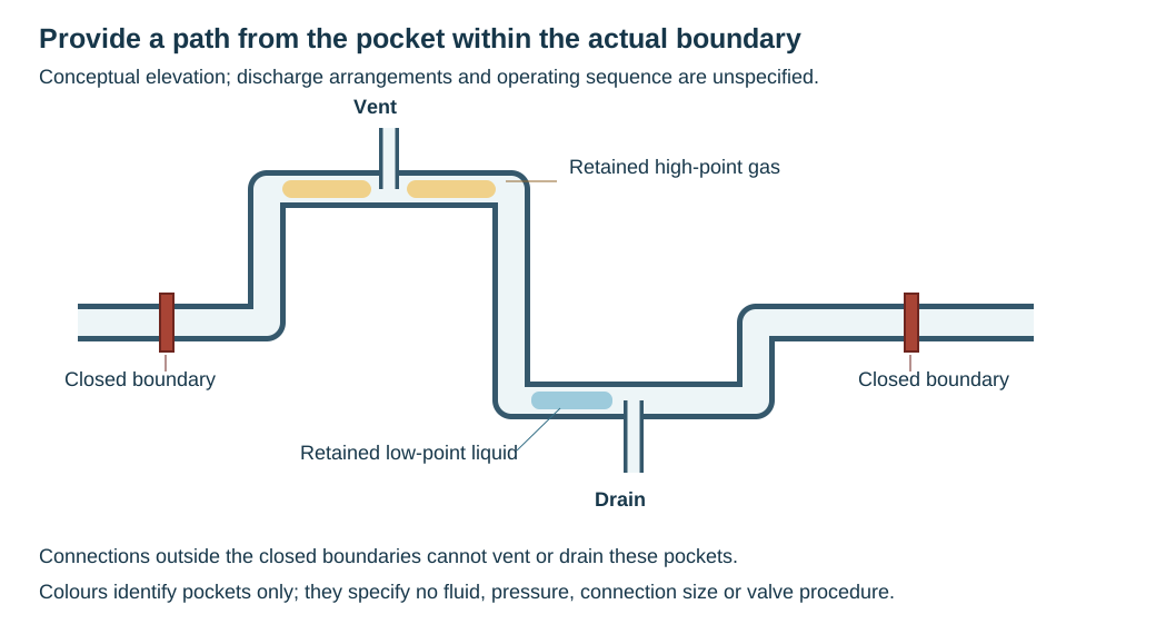
Figure 7.2. The conceptual elevation shows one isolated segment with its own high-point vent and low-point drain. Closed boundary valves separate it from neighboring piping. The connections describe communication with the pockets. No fluid, size, valve sequence or discharge destination is specified.
Testing and operating connections can serve different duties. Under a test-connection procedure, hydrostatic vents and drains can be construction-drawing connections used for the leak test. They can have temporary valves where required and permanent plugs, caps or blinds afterward. Operational or maintenance vents and drains can require permanent valves and closure devices, shown on the process and piping drawings and accessible to personnel. The distinction governs hardware, records and reinstatement. A temporary test arrangement is not automatically an operating vent, and a convenient drawing omission does not erase a physically necessary test connection.
Opening a vent or drain can release pressure, hazardous fluid or a hot inventory. Connection size, closure, isolation and discharge destination must support the intended duty. A drain used repeatedly for maintenance needs a practical operating position and a route for the removed contents. An atmospheric discharge acceptable for one harmless test medium may be unsuitable for process service. Utility architecture and Hazardous services develop receiving-system and exposure conditions; Pressure protection develops trapped pressure and thermal relief.
A connection detail carries its notes as well as its shape
Select the connection family with the material class, header size, duty and required joint/examination basis. Threaded, socket-welded and butt-welded assemblies do not have the same fatigue, crevice or fabrication consequences. A fully examined welded system can call for a flanged construction that preserves its examination route. An extended-body root valve can reduce separate pieces but changes mass, geometry and repair choices. Two root valves change isolation capability and increase the attachment’s length and mass.
Plastic-lined piping needs a connection that preserves the lining through the branch or instrument tee. PVC/CPVC, polypropylene, tubing and ductile-iron arrangements use their own joint systems. The metallic connection’s detail cannot be transferred by replacing only its material name. Compression fittings require the specified tube dimensions and assembly. A flanged nonmetallic connection needs its own load distribution and bolting treatment. Materials and Joints establish those compatibilities.
Changing the selected detail also changes the material take-off. A project substituting an integral outlet for a separate nipple assembly must make the class/detail relationship and permitted uses explicit. This keeps early procurement and final design consistent. A drawing selected in one area should not quietly introduce a component excluded by the governing material specification in another.
Insulation creates a practical conflict with an unrestricted preference for short nipples. The connection needs enough extension to keep the required valve, closure or joint accessible without compromising the insulation’s function. One adopted connection procedure specifies an insulated-pipe nipple length of at least 75 mm or the insulation thickness plus 25 mm, whichever is greater:
is nipple length and is insulation thickness in that procedure. The original paired inch values are 3 in and 1 in plus insulation thickness. They are alternative rounded unit conventions, not exact conversions. Use one specified unit basis consistently. This condition is not a universal length rule or a vibration acceptance test.
If the extension makes the attachment mechanically unsuitable, change the assembly or support arrangement rather than silently violate either requirement.
Follow the closure, valves and joint system through the detail

Figure 7.3. Selected test closure and operating root hardware motifs.
A test plug closes the selected test vent or drain after its communication duty. A blind flange provides a different closure and a bolted sealing interface. A single operating root adds a valve between the process attachment and its specified end closure. A dual-root arrangement adds another valve and connecting length. The two valves increase mass and extension as well as changing the available isolation arrangement. Their number alone does not establish a verified intervention boundary.
The illustrated threaded test tee and single-root arrangement are distinct from the selected socket-weld dual-root construction. Its process-side valve has socket-weld ends, while its outer valve provides the specified socket-weld-to-threaded termination for a plug. Preserve those end types and the intervening plain-ended nipples in the material take-off. Do not substitute a threaded assembly because its symbols look similar. A line-class choice and header-size range select the actual construction. The dimensionless motif selects neither.
The lined instrument tee preserves its lining through a dedicated tee and uses its flanged valve and blind closure. The lining, tee geometry, valve ends and bolted seals form one pressure and chemical boundary. Replacing that motif with a drilled bare-metal outlet discards the lining duty. Conversely, a lined flanged detail does not provide the joint system for PVC/CPVC, polypropylene, tubing or ductile iron. Those retain their own specified sockets, flanges, fusion, compression or mechanical joints.
Structured variant relationships identify the interfaces. Select the actual class/detail with its header-size and material notes, insulation extension and evaluated mass/support/access. Changes to outlet or valve ends must reach the class, detail and purchase record.
Table 7.2. Connection duties and installation consequences.
| Connection duty |
Distinction to preserve |
Installation and operating consequence |
| Hydrostatic test vent/drain |
Defined test boundary and high/low pocket; temporary versus permanent hardware |
Filling and emptying communication, then specified permanent closure and reinstatement |
| Operating or maintenance vent/drain |
Repeated duty, accessible valve/closure and discharge route |
Safe operation, isolation, contents removal and condition inspection |
| Pressure instrument root |
Pressure communication and isolation plus attachment mass |
Root-valve integrity and instrument removal without assuming measurement performance |
| Thermowell |
Pressure-retaining connection plus an immersed cantilever |
External connection integrity and separate flow-induced response of the well |
| Orifice flange taps |
Two pressure leads, their root connections and service conditions |
Compatible isolation/support and maintained differential-pressure paths |
| Sample connection |
Representative withdrawal arrangement, containment and mechanical connection |
Service-compatible sample route and intervention; local branch strength alone does not establish sample quality |
Entry geometry must permit the intended work
Connection height and sensor insertion solve different problems. A perpendicular thermowell connection, an oblique lateral entry and an entry along an elbow create different insertion paths. Selected small-header arrangements can enlarge a short barrel between reducers to make room for that path. Other material and size families use a tee, instrument tee or tapped flange instead. A mounting projection or locally enlarged pipe does not establish the well's effective immersion, representative sensing or flow-induced response. Coordinate those separate evaluations with temperature measurement and the actual well geometry.
Reduction can also create a retained pocket. A selected pipeline thermowell arrangement uses eccentric reduction with its flat side at the bottom where a pocket-free horizontal path is required. Its vertical arrangement uses another geometry. The practical question is whether the actual internal path drains and communicates as intended. Transferring that orientation to every reducer would discard the conditions that made the detail useful. So would importing a metallic outlet weld into a lined or polymer assembly.
Orifice pressure taps illustrate a different access conflict. Staggered nipples and 45° elbows can separate adjacent valves and their ends, while leaving no straight path to rod out a blocked connection. In one adopted double-valve orifice-tap detail, the rod-out variant removes the 45° elbows. It rotates the orifice flange by one bolt hole and uses two nipples each 100 mm long. The paired drawing convention is 4 in.
This is a selected geometric alternative, not a general field instruction: preserve the actual pressure-tap orientation, measurement arrangement, class/material construction and permitted intervention. Resolve those interfaces before choosing the access variant.
The same detail calls for support when two valves are at the end of an elbow or nipple because their moment arm loads the root. Providing rod-out clearance does not remove that demand. Changing nipple length or valve position changes it. The support must carry the evaluated assembly load while preserving the parent pipe's relevant motion and the sensing lead's function. Two serial valves alone do not establish an intermediate bleed, demonstrable isolation or permission to open the connection.
Valve removal can leave a lead/fitting unsupported. Rod-out requires a withdrawal/tool path and an established containment procedure. Preserve those configurations and restore selected valves, closures, supports and sensing paths after work.
Sensing and sampling have mechanical interfaces
The pressure root connection, instrument tubing and instrument support form a load and movement path as well as a fluid path. A stationary instrument connected to a moving pipe needs a lead arrangement that accommodates the relative movement. Tubing secured along the line can follow it. The transition to a stationary support must not impose an unintended restraint or sharp cyclic bend. An instrument mounted directly on a long root connection adds its mass to the appurtenance.
Pressure leads can encounter pulsation, retained liquid, blockage or contamination. Root-valve and connection geometry must preserve the required pressure communication and the maintenance isolation arrangement. Their mechanical adequacy does not establish measurement accuracy. Instrumentation explains the sensing conditions, impulse arrangements and control function, while this chapter establishes the pressure boundary and mechanical interface.
A thermowell introduces an immersed cantilever into the flow. Its wake can excite the well by vortex shedding. The external nipple/valve assembly’s natural frequency is a different evaluation. Flow velocity, well geometry and the relevant structural response enter the thermowell check. A connection selected for pressure alone does not establish that the inserted well will resist flow-induced fatigue. The instrument chapter owns the temperature-measurement arrangement and the mechanical-analysis chapter develops vibration evaluation.
A sample point likewise has two duties: obtaining the required fluid sample and preserving containment during withdrawal and intervention. Fluid phase, retained pockets and the withdrawal arrangement affect the sample. Valve mass, connection geometry and discharge/support affect the physical installation. Keep both interfaces visible instead of treating a sample valve as an ordinary spare branch.
Inspect the vulnerable detail and reevaluate changes
Inspect attachment welds, thread roots, nipple transitions, support contacts and hidden insulation/deposit surfaces. Vibration evidence must represent active equipment and flow states; shutdown behavior does not establish response during startup, slugging or changed pump combinations.
A cracked or leaking attachment calls for a diagnosis of the mechanism and affected boundary. A brace that arrests visible motion may leave a crack or introduce harmful thermal loading. Removing a vibrating instrument reduces mass but can also remove a needed sensing or protective function. The intervention must restore all required duties, with the examination, repair and return-to-service route in Operating integrity and Modification.
Change records should identify the actual assembly. A second valve, thicker insulation, heavier actuator, longer temporary hose or relocated support changes the former analysis basis even when the connection designation is unchanged. Reevaluate the root, parent pipe and attached lead together. After testing or maintenance, restore permanent closures, selected valves, supports and insulation, and confirm that intended communication and isolation paths remain available.