Chapter 13 — Utility and service system architecture
Deliver the function at the consumer
Utility architecture must deliver the consumer's required pressure, temperature, composition and cleanliness through startup, normal/low demand, source/driver loss, shared-item maintenance, shutdown and restoration. Distribution and return/drain/disposal paths affect those conditions. A failed exchanger or valve can expose a low-pressure utility collector to high-pressure process fluid.
Standby equipment needs an available driver, auxiliaries, source and transfer path during the duty-system failure. Shared vulnerable utilities can defeat otherwise duplicated pumps, compressors or fuel supplies. Branches, buried routes, pressure protection and measurement/control supply the related physical interfaces.
Balance fuel supply without losing combustion quality
A refinery fuel-gas system combines variable sources and distributes fuel to furnaces and boilers. The production and consumption rates need not change together. If a producer trips, pressure falls unless stored gas or makeup replaces the deficit. If a major consumer trips, pressure rises unless another consumer accepts the surplus, storage absorbs it or gas is disposed of through the defined protection route. Balancing fuel oil and gas at suitable dual-fuel consumers can accommodate part of this variation while maintaining the required heat input.
The mixture must also remain acceptable to the combustion equipment. Changes in density and heating value affect the relationship between gas delivery and combustion air. For mixtures within a limited hydrocarbon/hydrogen family, density may provide a useful correction signal. Adding substantial inert gas or carbon monoxide changes that relationship. Density alone no longer represents the combustion requirement adequately.
A system combining such sources needs a composition or Wobbe-index basis appropriate to its burners. The choice and installation of the measurement belong in measurement and control systems.
The basic Wobbe index expresses volumetric calorific value relative to gas density:
In this equation, is calorific value per unit gas volume at a stated reference temperature and absolute pressure. is the dimensionless specific gravity of that gas relative to air on the same reference basis. The index has the units of the volumetric calorific value. It is not dimensionless.
State whether the calorific value is gross or net, the reference conditions and the units before comparing values.
A temperature-dependent turbine definition, a value using net rather than gross heat, or a mass-based expression cannot be compared directly with this basic volumetric index.
Equal Wobbe index can preserve the heat-input relationship at a given burner pressure, but it does not guarantee the same flame behavior. Gas composition, particularly hydrogen content, still matters. Gas-turbine fuel evaluation therefore includes the specified index definition, its permitted absolute variation and rate of change, and the accepted composition range. Temperature adjustment can alter density and help maintain the pressure-drop/heat-release relationship while leaving a composition-driven flame difference unresolved. A backup-fuel change must meet both aspects of combustion behavior.
A mixing vessel, buffer vessel and knockout vessel describe functions. One vessel may perform more than one, but the combined design must establish each function. Buffering requires usable inventory between pressure limits. Mixing must reduce the rate and magnitude of composition changes sufficiently for the consumer. Liquid separation requires suitable inlet behavior, settling or demisting provisions and drainage.
Combining streams of similar composition may need less deliberate mixing than joining strongly dissimilar streams. Potentially fouling gas also changes whether a demister is maintainable. A fine separation device that plugs can defeat a continuously required supply.
Liquid carryover threatens the consumer even when the upstream gas looked dry. Expansion cooling, water saturation after scrubbing and heavier hydrocarbons can produce liquid after a pressure reduction or along a cooling route.
Review each proposed source for pressure, temperature, water, composition and chemical compatibility with the other sources.
Heating can prevent a specified condensation case. Knockout provision removes liquid that nevertheless arrives. These functions complement each other. Filters address solid contamination, such as scale dust, and need an arrangement that allows cleaning without an unintended fuel interruption.
A mixed refinery header and a gas-turbine fuel supply cannot be treated as interchangeable. A turbine can impose tighter composition and Wobbe-index variation limits, higher pressure and a requirement for dry, superheated gas. Waste gas and very low-pressure offgas may instead need dedicated burners with combustion support. Their varying flow and quality can make them unsuitable as an ordinary interchangeable fuel source. Backup fuel selection therefore includes:
The actual consumer's accepted fuel envelope.
The transition in combustion control.
The source available before the process has begun generating its own fuel.
Heating and liquid removal answer different questions. In the turbine-fuel conditioning method considered here, liquid formed after compression or mixing is removed at the primary knockout stage. It is not re-vaporized into the gas by heating. Downstream superheating then protects the separated gas against renewed condensation. An apparently dry stream leaving a heater does not establish that the required liquid-removal function occurred.
The final turbine-package knockout remains a further protection boundary, not a substitute for an upstream conditioning system that routinely delivers liquid.
The temperature margin retains its application. This turbine route requires gas at least 20°C above its dewpoint. A refinery route addressing predicted butane/heavier-component condensation after LPG makeup instead uses at least 5°C above the fuel-gas dewpoint and maintains that state in downstream piping. These margins belong to their different consumer/conditioning routes.
Dewpoint changes with composition and pressure. A reference-volume heating value is not a dewpoint measurement. Heat tracing and insulation must preserve the chosen downstream condition through the real route.
Pressure selection at the heater also changes where a leak goes. This turbine method places the heating medium below fuel-gas pressure to avoid heating-medium contamination of the fuel after cross-leakage. The resulting gas-to-heating-medium path still needs assessment. Protecting the consumer can expose a utility receiver, drain or return to hydrocarbons. A steam-heated LPG-vaporiser arrangement combines a steam-supply non-return valve with high-pressure detection on the steam side.
That detection initiates isolation of both steam supply and condensate collection. A check valve on the supply alone does not address the condensate escape path. These are conditions of that adopted arrangement. The complete protective function still needs its own design and verification.
Backup response depends on the cold standby state as well as installed capacity. Condensate retained in the heating coil can inhibit heat transfer when LPG vaporisation is suddenly demanded. A drain vessel with a pressure-balancing connection to the coil inlet permits drainage in the specified steam-heated arrangement. Buffer inventory, vaporiser response and consumer changeover must work together. Base-load changeover is the stated objective unless a separately accepted load reduction is required.
A turbine with a second gas manifold can also lose the option for liquid-fuel firing. Inert-gas blending introduces the converse upset: loss of the inert source changes fuel composition and Wobbe index.
Verify the permitted gas with and without that supply, rather than crediting normal dilution as a permanent property.
Structured fuel-state data keeps the two temperature-margin examples and the different pressure paths separate.
Turn a pressure range into usable inventory
Begin buffer sizing with a mass balance over a defined interruption.
If a net deficit remains approximately constant, the required released mass is
In this equation, is gas released from the buffer in kg. is consumer demand minus continuing supply in kg/s, and is the duration in s. If the deficit varies, use its time integral. The relevant duration is the time needed for the chosen makeup, consumer adjustment or backup to become effective. It is not automatically the longest imaginable plant outage.
For an educational estimate, assume a rigid vessel containing one ideal gas at constant temperature. The usable mass between its upper and lower absolute pressures then gives
In this equation, is vessel gas volume in m³. is absolute temperature in K, and is molecular mass in kg/kmol. The gas constant is Pa·m³/(kmol·K). Pressures are in Pa. Both pressure limits are absolute.
Their difference has the same magnitude when both are expressed on one gauge-pressure basis. A detailed gas inventory calculation must account for temperature change and nonideal behavior where they matter. Pressure-control behavior and the usable vessel pressure range must be consistent with the delivered header pressure.
Where the vessel must accept surplus as well as supply deficit, evaluate both directions from normal pressure. Starting near minimum pressure leaves little discharge reserve despite a large total volume. Inlet/outlet, controls, separation space and relief remain separate vessel requirements.
Keep liquid fuel pumpable and usable at the burner
Liquid-fuel temperature serves several different purposes. Storage temperature must permit withdrawal. Suction conditions must permit reliable pumping. Delivery temperature must produce a viscosity the burner can atomize. Heater surface temperature must avoid local decomposition, flashing or coke formation.
One temperature limit cannot represent all four.
A circulating fuel-oil loop carries fuel from storage through pumps, heaters and filters to the consumers, with a controlled return to pump suction. Circulation preserves the distribution temperature as consumption changes. For a refinery residue-fuel arrangement adopting a return-flow criterion of at least 20% of pumped flow at design consumption, write the flow balance explicitly. If is consumed flow, is returning flow and , the criterion implies . A longer or more exposed loop may require more return to control heat loss.
Keep all volumetric flows on a consistent temperature/density basis.
Pressure-atomized and steam-atomized burners have different supply requirements. A residue-fuel system adopts a maximum burner-inlet viscosity of 20 mm²/s. Under that criterion, use the fuel's viscosity–temperature relation to determine the delivered temperature. The number is a criterion for that combustion arrangement, rather than a universal fuel property. Steam atomization introduces an additional concern.
Fuel that cools the atomizing steam enough to condense it can impair combustion. A light startup fuel selected only because it is easy to pump may still be unsuitable for the burner arrangement. When a high-pressure oil loop feeds a lower-pressure burner loop, evaluate the overpressure path as well as the normal pressure-control duty.
The storage arrangement depends on the particular residue fuel. A lower-temperature tank containing water cannot simply receive hot loop return if the return would overheat its contents. A short-residue arrangement stored above the boiling region of water has a different concern: leakage from steam or hot-water coils introduces water into hot oil. A heating method that is reasonable for one storage condition can be unacceptable for the other.
Trace heating also needs a maximum-temperature basis for stagnant lines and thermal-expansion relief where liquid can be trapped. It needs access that permits valve removal without destroying the heating arrangement.
Insulation and tracing develops those details.
Filters and strainers need differential-pressure observation, venting and drainage, and a switching arrangement compatible with continued fuel supply. The flushings also need a destination and protection against hot splashes. A nominally spare filter is of little value if cleaning it contaminates the live loop or requires stopping every consumer.
Shutdown changes the fuel state. High-viscosity fuel can leave a line difficult to restart or maintain, so lighter compatible fuel or a specified displacement method may be required before draining. Direct injection of a volatile flushing oil into a hot loop can flash its light constituents. A steam-out arrangement can also admit oil into the steam network unless its connections prevent backflow.
Develop the line-up around the compatible flushing medium and its actual temperature and pressure.
Include a reception facility that can accept the displaced inventory.
A cold, uncirculated backup must not be credited as immediately available when the emergency demand requires hot, pumpable fuel.
Establish blend stability before relying on viscosity reduction
A low-viscosity diluent can make a residue easier to pump while making the mixture unstable. Incompatible streams can flocculate asphaltenes and foul heaters, filters and burners. Crude origin, processing history and thermal-cracking severity therefore matter alongside the measured viscosity. Straight-run and thermally cracked residues are not presumed compatible. Where behavior is uncertain, laboratory blending tests at operating temperatures establish the proposed blend's stability.
Commercial fuel-oil blending correlations alone are less dependable for the heaviest residue grades. Hot residue mixed with a light component can also flash before any intended viscosity benefit reaches the burner.
Mixing equipment must fit that fouling behavior. In the adopted residue-fuel method, good in-line or vessel mixing is required. Static mixers are excluded for cracked fuels because of blockage risk. The storage tank is not used as the mixing vessel. These local choices explain why adding a mixer symbol or taking an average tank sample is insufficient.
The demonstrated blend, temperature range, mixing path and contamination/fouling observations become inputs to the distribution design.
The system choice is likewise not determined by viscosity alone. A residue producing gas during storage through after-cracking is assigned to the asphalt-burning route even where its viscosity overlaps the ordinary residue-fuel ranges. The route must handle evolving gas, coke/sludge and a higher temperature needed for atomization. Raising temperature indefinitely is not an answer. Heater film temperature governs degradation, and bulk outlet temperature includes the heat-transfer approach.
The most remote burner loses temperature in distribution.
An illustrative thermal chain in this asphalt method uses a typical 330°C film ceiling and about 300°C bulk outlet. With up to 20°C distribution loss, this gives about 280°C at the burner. These are a linked example of that source method, not universal material limits. The actual cracking temperature depends on residue origin and history.
Establish that the residue reaches required burner viscosity at a temperature compatible with its stability and the heat-loss allowance.
Otherwise a demonstrated compatible diluent or a different fuel arrangement is needed. The nominal heater outlet cannot prove the whole chain.
Keep the return-flow denominator with its thermal purpose
The ordinary residue-loop criterion above defines return as a fraction of pumped flow. The asphalt-burning method instead requires return flow not less than design consumption, together with sufficient circulation to keep return temperature within 20°C of heater outlet. Its initial design guidance also gives a minimum circulation velocity of 1 m/s. The circulation-pump section asks for turbulent flow throughout the loop. Flow, temperature loss and flow regime remain separate checks.
A minimum volumetric return does not prove the required velocity in every branch or the regime of a temperature-dependent viscous fuel.
With consistent volumetric references, and the asphalt condition gives . This is a different thermal duty from the ordinary 20%-of-pumped-flow criterion. Structured return-flow methods.
Carry circulation close to the consumer so short offtakes leave little stagnant inventory.
Sub-loops must preserve circulation, isolation and flushing for the consumers that may shut down together. Tracing protects the interrupted-circulation state. It does not replace the heater/circulation duty at the higher distribution temperature. Relief, drain and stagnant branches also need their defined protection against blockage.
Startup and shutdown use a lower-viscosity compatible fuel in this asphalt route, and the consumer's fired equipment must be hot and operating before asphalt is introduced. Flushing points must reach dead legs and isolated sections, prevent residue backflow into the flushing supply and deliver displaced fuel to a suitable receiver. A flushing medium so light that it flashes on entering the hot system defeats that purpose. The available hot backup, maintained standby pump and actual changeover time therefore belong in the availability assessment, together with the blend and thermal-stability evidence.
Remove condensate under the pressure conditions that actually exist
Steam cools and forms condensate in distribution piping, tracing and equipment. Low points, sections upstream of vertical rises, terminal points and equipment outlets can retain this liquid unless drainage is provided. The purpose of a steam trap is to discharge condensate, air and other noncondensable gases while preventing or limiting loss of live steam. The arrangement must allow the liquid to reach the trap and then leave it.
Startup and running loads differ. Heating cold pipe or equipment can create a substantial initial condensate load. Steady operation may be governed by heat loss or process heat transfer.
Determine these loads by measurement, a heat-duty calculation or equipment data.
Then evaluate the trap at the inlet pressure remaining after control valves and equipment.
The nominal steam-header pressure is not necessarily the trap inlet pressure.
Trap outlet backpressure includes receiver or return-header pressure, the static head of any lift after the trap, and friction losses. With consistent pressure units, a useful balance is
In these equations, is outlet backpressure, and is receiver/header pressure. is pressure at the trap inlet, and is downstream friction loss. All are in Pa. is the assumed liquid density in kg/m³. is gravitational acceleration in m/s², and is upward lift in m.
The static-head term is a liquid-column estimate. A detailed two-phase return calculation may not behave as a completely flooded liquid line. An existing return system merits a pressure survey because the actual backpressure can differ from the original calculation.
If outlet backpressure reaches or exceeds inlet pressure, a larger ordinary trap cannot create the missing driving differential. A pressure-powered pump or appropriate pump/trap combination addresses this stall condition.
Capacity and operating principle must both fit the application. For a trap-selection procedure adopting the following factors, rate the selected trap for the factored condensate duty at the applicable differential pressure.
Table 13.1. Conditional steam-trap sizing factors.
| Application |
General sizing factor |
With temperature control |
| Steam-main drainage or tracing |
2 |
No separate factor specified |
| Heat exchangers and general process equipment |
2 |
3 |
| Space unit heaters or air-heating coils |
2 |
3 |
| Submerged coils, including siphon drains |
2 |
No separate factor specified |
| Rotating cylinders |
2 |
No separate factor specified |
These are conditional selection factors, not added physical condensate generation. A blank temperature-control entry does not establish an additional factor. The structured companion preserves the application and blank distinctions: trap selection data.
Apply the selection duty at the actual inlet/backpressure condition and assess startup separately. A sizing factor cannot prevent stall as a control valve reduces steam pressure.
Different trap families remain useful alternatives. Under one scoped selection basis, float-and-thermostatic traps are the first choice for separators and many process applications. Inverted-bucket traps are an alternative, and are the first choice in the higher-pressure process range. Balanced-pressure thermostatic and thermodynamic traps are alternative tracer choices, with the preferred order depending on product temperature. That same basis excludes thermodynamic traps when application backpressure exceeds 50% of inlet pressure and requires manufacturer evaluation for superheated steam.
Final selection needs the particular trap's capacity and operating envelope at the actual differential.
Arrange drainage, recovery and maintenance together
Place the trap near and below the condensate source where the application permits, with accessible isolation, strainers and test or depressurization points. Coils using siphon drains are a distinct arrangement. Elevated or pressurized returns can need downstream check valves to prevent reverse flow. Open discharge has different auxiliary equipment from a closed return and needs consideration of hot, high-velocity discharge, noise and erosion. Individually trapping condensate removal points avoids making dissimilar consumers share one pressure-dependent drainage decision.
A non-pumped return normally carries condensate and flash steam toward a collection vessel. A pumped header conveys a fully flooded liquid stream. For a condensate-return procedure that prohibits direct trap discharge into pumped headers, that prohibition must survive the layout. The same procedure requires a sloping, freely draining non-pumped header without vertical risers, and limits flash-steam velocity to less than 20 m/s. Its stated minimum slope is 1 cm in 24 m, approximately 0.000417 m/m.
It is a local minimum for that return arrangement, not a sewer slope or a universal promise of drainage. A trap outlet may need a local lift, but that does not authorise a riser in a header whose adopted rules exclude it.
Freezing climates add another state: steam is absent while liquid remains. Self-draining inlet and discharge piping removes some of that risk. Where it cannot be achieved, the trap and trapped piping need suitable freeze protection. Steam distribution and condensate collection manifolds can simplify tracing connections and maintenance, but they must preserve the intended individual circuits, drainage and isolation. The thermal purpose and circuit details belong in tracing and thermal protection.
Distinguish added drainage capacity from continued drainage after a failure
Parallel traps on the same equipment can supply combined capacity or preserve drainage with one path unavailable; these are separate requirements. Define whether continuity means full load, established reduced load, startup or controlled shutdown, including acceptable interruption and response time.
For the selected maintainable parallel arrangement, each path has isolation valves, a strainer, downstream check valve and access to service it without disturbing its neighbor. Redundant drainage applies where trap failure cannot be tolerated; a globe-valved bypass/drain is a conditional alternative where maintenance cannot await equipment shutdown. Hardware duplication alone proves neither remaining capacity nor maintenance isolation.
This is distinct from group trapping independently controlled consumers. Combining their outlets before one trap can let higher pressure inhibit the lower-pressure consumer's drainage. Individually trapped points retain separate drainage duties even where their downstream return is shared. Identify distinct equipment pressure spaces before treating them as one source.
Evaluate the available paths at their actual pressure and load
Parallel traps receive condensate from a common source, but their inlet and outlet pressures need not be exactly equal at the devices. Branch losses, elevation, strainers, check-valve resistance and intermittent discharge affect each path. The common return can change pressure as total condensate and flash-steam flow change. Neither a symmetric sketch nor identical nominal trap sizes proves a stable 50/50 load split.
Evaluate each selected trap's capacity and operating envelope at the pressure difference it actually retains.
Include startup, normal operation, minimum load and the required one-path-out state.
For a simple capacity screen on a stated state, first evaluate the trap and branch pressure conditions. Let be the available condensate-discharge capacity of path , in kg/h, after that evaluation. Let be the selection duty for that state, in kg/h, including the adopted sizing factor. The available-path comparison is
In this equation, contains only the paths available in that configuration. This is a necessary aggregate capacity comparison, not a hydraulic solution proving that the source feeds every path at its listed capacity. The common inlet and return must carry the resulting flow, and the trap operating principles must suit the duty. For full-duty continuity with either of two paths unavailable, the corresponding remaining path must meet the required selection duty by itself. A different maintenance duty is legitimate only when the associated process load reduction and operating limits are established.
For a reduced maintenance duty, establish the associated process load reduction and operating limits before crediting remaining capacity. Passing the unfactored physical load is not proof that the adopted factored selection duty is preserved. Capacity must remain valid at changed pressures, including startup.
A second ordinary trap cannot restore driving pressure when the common return exceeds inlet pressure. A qualified lower-pressure receiver or pressure-powered transfer addresses that different problem.
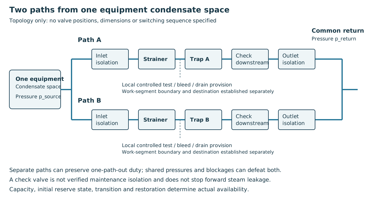
Figure 13.1. Authored functional topology for two paths draining one equipment condensate space to a common closed return. Each path has its own isolation, strainer, trap and downstream check function. Local test/depressurization provision and access belong to the actual maintainable assembly. The drawing specifies neither valve positions, component dimensions nor a field switching sequence, and it does not establish automatic standby action. Shared source and return pressures remain common causes. Structured topology, states and capacity examples accompanies the figure.
Make the maintenance configuration demonstrably available
A blocked strainer/closed trap can accumulate condensate, reduce heat transfer and cause damaging liquid movement. An open-failed trap can pass live steam into the return, raising temperature, steam loading and backpressure. Its downstream check limits reverse flow but neither stops forward leakage nor verifies maintenance isolation. Identify and isolate the failed path before crediting a healthy sibling.
Shared debris, closed/obstructed common inlet, flooded or overpressured return, lost driving pressure, freezing and common maintenance errors can defeat both paths. Strainer cleanout and removal access must leave the other live path and its supports/boundary undisturbed.
An isolated standby is unavailable until its actual detection/changeover interval and condensate accumulation are acceptable. Cold retained water or obstruction can cause thermal/liquid transients during changeover. One-path-out capacity and transition behavior both constrain the arrangement.
Maintenance isolation must address equipment pressure, return pressure and hot trapped liquid, with controlled depressurization/drainage to a suitable destination and means to verify no repressurization. Closed valves can create additional pockets. Resolve access, flash discharge and adjacent live-boundary integrity through verification and intervention.
A globe-valved bypass or separate drain does not discriminate condensate from live steam. Establish duty, receiving pressure/capacity, steam loss, discharge destination, monitoring and permitted duration as a separate operating state. Restoration must prevent a bypass defeating the trap. Verify drainage and absence of unacceptable steam leakage at relevant loads/pressures, observing the common return; a hot outlet alone is inconclusive because hot condensate and flash steam can be normal.
If remaining capacity, isolation, receiver loading or changeover cannot support continued service, plan equipment interruption rather than credit unverified duplication or bypass operation.
Compact the assembly without losing its operating orientation
A trap assembly spread across the floor can sometimes be replaced by a vertical-leg arrangement. A vertical tracing manifold supported from a column can preserve space for adjacent piping and people. The available thermodynamic-trap example moves the trap and strainer into the vertical leg and adds a low drain. It presents a space-saving alternative, not proof that every trap can operate in either orientation.
When assessing the compact arrangement, preserve the following for the selected trap:
Operating orientation and gravity path to its inlet.
Strainer cleanout and isolation.
Drain destination and withdrawal space.
Reducing plan area while leaving water trapped below an inaccessible strainer would exchange one layout problem for an operating problem.
A manifold's shared structure does not merge its individual circuit duties.
Identify each supply/return circuit, its valve and drain path, and keep connections accessible for tracing work and restoration.
The useful comparison is the completed installation in operation, shutdown, freezing weather and maintenance—not simply the width of a symbol. Layout supplies the surrounding work space and tracing supplies the thermal circuit basis.
Tracing requirements also retain their intervention scope. One plant-layout rule requires tracing and insulation of the flare system when the operating philosophy is to steam equipment out to flare. An exception within that same basis permits the responsible engineering authority to waive the requirement following a risk review. That is a conditional decision within a particular steam-out procedure and service basis. It does not waive an independent thermal duty, retained-water freeze protection or the consequences of exposing surrounding material to the steam-out condition.
Keep the reviewed exception with the changed arrangement and verify the duties it leaves in place.
Give heat-transfer fluid a controlled circulation and inventory path
A heat-transfer-fluid system carries energy through a circulating liquid. Pumps deliver fluid to a fired heater or heat-recovery unit, hot supply feeds the consumers, and the cooled return completes the circuit. The fluid must remain pumpable during startup, avoid damaging film temperatures in the heater, and retain sufficient pressure at high points to avoid unintended boiling. A short hot supply route can reduce the time fluid spends at its maximum temperature and thereby limit decomposition.
The expansion vessel accommodates expansion, operating inventory and removal of inerts, residual startup water and low-boiling degradation products. An elevated return-side vessel at pump suction can provide venting and suction head. Lower placement requires provision for vapor locking, shutdown drainage/overflow and positive pressure at the highest point.
Vessel connection topology is a separate choice from its elevation. For an HTF arrangement adopting full flow through the expansion vessel:
Route the circulating return through the vessel.
Design both vessel and connecting piping for that flow.
Fluid then passes through the inventory and degassing location before reaching pump suction. A cold-fluid vessel connected by a single leg is a distinct alternative. The main return bypasses the vessel, so the connection cannot be credited as a full-flow degassing path. Under this design basis the single-leg alternative requires specific project-authority approval.
It must retain the required expansion, venting, suction and pressure functions through its own evaluated arrangement. It is not an interchangeable simplification of the full-flow connection.
Suction margin depends on the fluid as it exists in service. Aged fluid or material absorbed from a connected disposal system can have a different vapor pressure from fresh supplied fluid. The hottest or most degraded relevant state can therefore reduce available NPSH.
Establish pump requirements and the operating level/elevation accordingly.
pump systems develops the suction and pump behavior.
Heat demand can fall while the heater still requires a minimum fluid flow to avoid excessive film temperature. A bypass or spillover arrangement preserves circulation as consumers close. A fired heater can reduce firing only to its available turndown. A heat-recovery unit may have little control over the incoming heat. A trim cooler or another defined heat sink must then reject the surplus.
The circulation, heater and consumer controls have to be considered together rather than sized as independent line branches. A hot standby circulation pump also avoids exposing a cold machine to sudden hot duty.
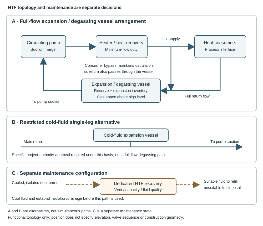
Figure 13.2. An authored functional schematic. Panel A shows the full-flow return through the expansion vessel. Panel B shows the restricted cold-fluid single-leg alternative separately; the two panels are alternative topologies, not simultaneously installed paths. The dashed path in panel C represents a separately established maintenance configuration after cooling and isolation. The drawing does not specify nozzle elevations, valve line-ups, automatic controls or construction dimensions. A dedicated recovery destination avoids mixing the fluid with unrelated plant drains. The structured companion records the functions and states: HTF configuration data.
Test whether blanket pressure actually supplies suction margin
Fresh-fluid vapor pressure can give a misleading pressure-head credit when degradation products or material absorbed from the connected disposal system are present. A particular HTF suction-assessment method addresses that uncertainty by assuming, at normal operating temperature, that the fluid vapor pressure equals the expansion-vessel pressure. This is an adopted assessment premise for the aged/contaminated fluid. It is not a law that every HTF has that vapor pressure or that every increase in blanket pressure changes it equally.
For a simplified vessel-to-pump liquid-column assessment,
In this equation, both pressures are absolute and use Pa. is liquid density in kg/m³, and is m/s². is fluid-surface elevation above the pump reference in m. is suction-path loss in m of that liquid. This expression assumes the stated surface-pressure and elevation references.
This is not a complete calculation for all inlet geometries. Under the selected equal-pressure premise, the pressure term cancels: blanket-pressure increase supplies no suction credit without a justified different fluid-pressure relationship. Low-low level, elevation and suction losses must meet pump-required NPSH and the adopted margin over relevant temperatures/degraded states. Expansion volume does not answer that suction question. Pump systems and structured assessment premise.
Size operating inventory by its purpose
Thermal expansion is a change in fluid volume. For a fixed mass whose cold and hot densities are known,
In this equation, is the total fluid inventory expressed as its volume at the minimum temperature in m³. and are fluid densities at the minimum and maximum temperatures in kg/m³. The equation follows from conservation of mass. It assumes the same retained mass at both temperatures and is an educational means of calculating the expansion volume used by the vessel-sizing method. It does not replace the actual fluid-property data or account for process ingress.
For an expansion-vessel procedure using a 20% addition to thermal expansion, the volume between low and high operating levels is
This procedure also assigns 25% of the total vessel volume to the inventory between low-low and low levels. It verifies pump suction margin at low-low level and the relevant temperatures. It reserves space above high level for gas–liquid separation and nitrogen. These quantities have different bases. 20% multiplies the expansion volume, whereas 25% multiplies vessel volume.
Adding the percentages together or treating their remainder as an automatically adequate vapor space would lose the method's meaning.
Total vessel sizing must additionally meet low-low inventory/suction requirements, inlet behavior, gas separation and credible upsets.
An HTF storage tank serves another function: it receives fluid removed from the circuit. One procedure requires full drainable inventory plus 10% makeup allowance. The tank's other geometric and operating requirements still need assessment. This is a storage allowance, not the expansion-vessel allowance. Parallel trains can justify storage for one train only when simultaneous drainage of more than one train is excluded by the actual maintenance plan. Similarly, a dedicated maintenance collection vessel is sized for the largest consumer or group that may be taken out of service together.
Account for pressure ingress, drying and recovery
An exchanger joins two systems separated by a heat-transfer boundary. If process working pressure exceeds HTF working pressure, a tube failure can displace HTF and introduce process fluid into the circulating circuit and expansion vessel. The working-pressure relationship can be opposite to the design-pressure relationship.
Review the actual credible pressures and the flow path remaining through valves to the expansion vessel.
Where isolation interrupts that path, the higher-pressure design or local protective alternative needs its own evaluation. Expansion volume alone does not establish overpressure protection. Pressure protection supplies the broader method.
Initial commissioning must deal with water left from construction or testing. High and low points, including those inside equipment isolation valves, need usable vents and drains. Drying and startup need a route for water and gas removal. Fluid returned after maintenance must also be suitable for reuse. Mixing an aged or contaminated drain inventory with clean spare fluid can destroy the replacement inventory.
Sampling and disposition therefore precede a return to common storage when contamination is credible.
A dedicated closed HTF maintenance drain can recover cooled fluid for reuse or controlled disposal while reducing spillage. Under an arrangement using buried gravity drainage to a collection vessel, hot fluid must first be cooled. The drain is intended for cooled maintenance fluid. If gravity flow cannot be achieved, an aboveground nitrogen-assisted alternative may be considered with a suitable vent destination and pressure evaluation. The collection system must remain separate from other plant drains under that adopted arrangement.
Nitrogen blanketing limits air and moisture ingress but introduces a vent and atmosphere-control duty of its own.
Provide a practical means of returning suitable fluid, filling containers or disposing of unsuitable inventory.
Viscous fluid in a cold collection vessel may need heating to be pumpable. Fresh makeup can need controlled drying and removal of light ends. These functions should be arranged so that draining, conditioning and refilling preserve the required fluid state rather than merely move liquid from one vessel to another.
Preserve air quality and reserve at the farthest consumer
Instrument air carries control and protective action as well as pressure. The quality path starts at the intake. A compressor drawing contaminated air can distribute toxic, corrosive or flammable material. An intake filter or an oil-free compressor does not solve every gaseous contaminant. Compression, cooling and water separation remove different problems from drying and final filtration.
Cooling before the dryer reduces the water load. Separators remove liquid carryover. Desiccant drying removes moisture to the specified dew point. Afterfilters prevent desiccant particles from entering instruments.
The dew-point basis matters. A system adopts a requirement that dew point at operating pressure be at least 10°C below the lowest expected local ambient temperature. Under that requirement, a cold exposed branch is part of the assessment even if the dryer building is warm. A dew-point statement at atmospheric pressure is a different condition and cannot simply be substituted without conversion.
Increasing dryer capacity is also insufficient if liquid water bypasses the separator or a damaged filter carries particles downstream.
Desiccant drying alternates drying with regeneration and cooling. Regeneration can use heated air at atmospheric or operating pressure, or a heaterless process. The choice affects heat supply, valves, sequencing, own air consumption and maintenance. One design basis gives illustrative own-consumption ranges of 2–3% by mass for a heated atmospheric regeneration stream taken from dryer output. This compares with 10–15% for a heatless dryer.
These ranges belong to those configurations. They are useful when comparing compressor demand, rather than a universal correction for every dryer. Rapid depressurization can damage or fragment desiccant, and switching a regenerated bed before appropriate cooling changes delivered air temperature.
Monitor outlet moisture and filter differential pressure so deterioration becomes visible in the delivered function.
Estimate consumption from the actual positioners, actuators, enclosure purges, essential cooling/purging and accepted industrial users. A procedure allowing 30% for data uncertainty and early additions gives , with both flows expressed on one stated reference pressure and temperature basis. This allowance does not automatically include dryer-regeneration demand or usable reserve during compressor failure.
A buffer vessel carries supply from duty-machine failure until the standby source becomes effective and damps load/unload fluctuations. Its usable inventory lies between the initial pressure and the minimum acceptable delivery pressure, after distribution losses.
Establish the interval from real starting behavior.
Include the case in which an automatic start fails and manual starting is required.
A receiver with the right nominal volume but too low an initial pressure does not provide the claimed reserve.
Locate and connect the receiver so its air remains available to the intended consumers during the failure.
Provide drainage and maintainable isolation without defeating that function.
Architecture must match the maintenance pattern. A single header can be appropriate where the entire facility stops for the relevant overhaul and air interruption is permitted. Partial shutdown can require a second header or a ring-main arrangement with isolation that preserves supply to operating sections. Ring geometry alone does not prove continuity: the valve configuration and remaining supply path determine it. A pressure-drop calculation must include the most remote consumer at the required demand, not only the nearest branch.
Keep optional demand from consuming essential reserve
Tool and industrial air can impose large intermittent loads and provide contamination or backflow paths. Under an arrangement sharing a supply plant:
Keep these downstream systems separated.
Include their accepted demands in capacity.
As pressure falls, give instrument air priority.
Mobile compressors can be a better source for a large overhaul tool demand than permanently enlarging the plant air system solely for that short condition.
Priority air for essential utility and process sections is a further distinction. Section isolation under falling pressure can preserve upstream supply to those functions. Its sequence and setpoints must match the actual consumers and reserve. An individual valve required to act after general air failure can need a secured local buffer supplied through a non-return arrangement. That buffer must be assessed for the valve's actual consumption and required duration.
It should not be credited to every instrument merely because it is drawn somewhere in the network.
Breathing air is a separate service-quality and reliability question. The preferred arrangement in this utility design basis uses separate bottles for breathing equipment. Where a project adopts shared supply, the breathing-air standard, intake contamination checks, filtration, dedicated connections and guaranteed availability need explicit provision. Ordinary instrument-air cleanliness and pressure are insufficient evidence for that use. The same guidance excludes nitrogen and carbon dioxide as backup gases for the instrument-air network.
This restriction must remain explicit when that design basis applies.
During construction and maintenance, keep water, oil, cleaning fluids and debris from the distribution system. One instrument-air procedure specifies compressed-air pneumatic testing and air blow-through, and excludes liquids and other gases for that work. Adopted as such, it cannot be replaced by the usual hydrotest sequence simply because the piping material is metallic. Testing, cleaning and readiness develops test safety, boundaries and restoration. The local moisture and contamination consequences still govern this utility.
Separate supplied water, collected drainage and uncontrolled spills
Fire water, cooling water, process water and potable water have different duties. Cooling-water supply and return form a heat-removal circuit. The arrangement must serve exchanger locations without defeating access or crowding other buried services. Fire-water routing and isolation must preserve the required emergency coverage while a section is out of service. Water-service identity also determines contamination and disposal concerns.
A convenient spare connection is unsuitable if it creates an unassessed cross-connection between distinct functions.
Nominal reach does not remove a structural shadow
A monitor can have nominal range sufficient to encompass an equipment location while a process structure blocks the required path to it. The target's position inside a range outline therefore answers only part of the placement question.
Trace the monitor-to-target approach against actual structures, equipment elevations and accessible deployment positions.

Figure 13.3. The ground position has an obstructed path to the air-cooler target. The elevated candidate has a different approach above the intervening structure. These lines show physical visibility and obstruction, not water trajectories, range or accepted coverage. Structured obstruction and deployment alternatives.
An elevated candidate can address a structural shadow while introducing support, vendor-equipment, access and maintenance requirements. Another ground position or additional monitor can address a different target or approach.
Examine those alternatives against the complete target arrangement.
Improving the path to one air cooler does not establish coverage of adjacent equipment or a tall vessel.
A historical nominal-range comparison uses 150 psi nozzle pressure and 500 gpm, with a prevailing-wind qualification that has no numerical wind value. Those conditions do not establish a universal effective reach, and no range curve is reproduced or interpolated here. The actual nozzle, pressure, pattern, weather and target requirements must establish useful coverage.
For any selected elevated installation, preserve structural support, freezing conditions and reachable servicing positions.
Do not treat the elevation sketch as a firewater supply design.
Buried and aboveground cooling-water routes offer different tradeoffs. An underground header near exchanger channel ends can shorten laterals and preserve rack space. Aboveground routing improves direct access but can enlarge the rack and lengthen branches. Ground separation between hot return and cool supply limits unwanted heat transfer through soil. The useful distance depends on the adopted arrangement.
Foundation crossings and excavation space belong in buried-system routing, while channel removal and equipment access connect to exchanger arrangement. These interfaces should be resolved while the plot is still adaptable.
Gravity plant drainage separates streams by what they can contain and where they may go. Contaminated surface water and oily equipment drainage need the relevant hydrocarbon-recovery or treatment route. Chemically aggressive streams can need separate collection and neutralization or recovery. Sanitary drainage has another destination. Combining streams saves some pipe but can enlarge the treatment duty and introduce incompatibilities.
The design decision should include the receiving facility and credible rain/fire-water demand, rather than end at the edge of the process area.
A closed hydrocarbon drain collects intended releases from equipment while retaining containment. An open drain collects liquids reaching floors or paving. A sump that conveniently collects drips is not automatically complete secondary containment for a major inventory release.
Define its collection area, credible release volume, free capacity, alarm, removal capacity and access during an incident.
Pumps, vacuum connections and disposal routes differ between small maintenance drips, a substantial leak and a catastrophic release.
In one modular-facility architecture, frequent drains are hard-piped to a closed header, then to a low-pressure knockout drum for degassing and onward to slop storage. Equipment is drained within the process as far as practicable before final drainage. Positive separation at a blind or removable spool prevents the maintenance drain connection remaining an unintended process connection in normal service. Restriction devices limit the inflow where needed, but the header and receiver still need evaluation for gas blow-by. A high-pressure source does not become harmless once its first liquid inventory has left.
That architecture keeps aerated floor-sump liquid from the closed hydrocarbon collection path and provides a separate removal destination. It also recognizes that air-compressor and dryer packages continuously discharge water condensate and need suitable nearby collection. These are conditional choices for a defined modular installation. They explain why aeration, contaminants, frequency, pressure and receiving capacity govern segregation. They do not establish that every plant drain should enter a flare knockout drum or that every compressor condensate stream belongs in sanitary treatment.
An assisted equipment drain using nitrogen or fuel gas creates another pressure and gas-loading case.
Confirm the assisting medium's compatibility, the available pressure and the receiver venting.
Confirm the possibility of continuing gas flow after liquid removal.
Hoses and temporary collection connections also change the configuration. Their rating, restraint, connection security and reinstatement need attention. The physical branch detail and isolation integrity remain linked to vent and drain connections and the service hazards to hazardous-service mechanisms.
A supply break can move the hazardous-release boundary
A utility connection must be evaluated in its connected and disconnected states. A removable or turned spool with the required closure creates positive separation after an intermittent washing, steaming or blowing duty. A frequently used connection can have a separately selected blind arrangement. Neither provides continuous pumped injection in its disconnected state. The actual function and line-up matter more than a diagram's type number.
Continuous water or condensate injection into a sour process can use an intermediary break tank. It can interrupt communication back into the main utility supply while a pump supplies the process. This protects one boundary but creates another. If the pump stops and its check valve fails, process material can return through the pump into the atmospheric tank and expose nearby people to H₂S. A protected upstream supply does not establish that the pump/tank area is safe.
The adopted arrangement addresses that local path with a closed-top atmospheric tank, an elevated vent and low-pressure alarm on each pump discharge. Its particular closed-top detail requires the standpipe top at least 15 ft above the tank top.
Keep that local height reference.
It is not a generic safe-dispersion distance or an air-gap dimension. Vent destination, process pressure, release composition, tank/pump materials and the response to loss of injection still need their actual assessments. An alarm reports a condition and does not itself stop process backflow.
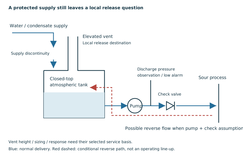
Figure 13.4. Authored functional diagram of the selected continuous-injection alternative. Blue arrows show normal water delivery; the dashed red path shows possible reverse process flow when the pump and check-valve assumptions fail. The supply discontinuity and the tank vent are separate interfaces. The sketch gives no air-gap size, vent sizing, trip architecture or qualified dispersion distance. Structured functions and failure conditions accompanies the diagram.
The same method prefers low-hardness water or condensate to limit calcium deposits that can plug the injection path. That water-quality duty is separate from positive isolation and from the H₂S release consequence.
When injecting into a pressurized system, verify forward injection pressure near the process connection.
Reassess loss of flow, check-valve behavior and venting through actual operating and shutdown states.
Sour-service mechanisms, pressure protection and measurement interfaces provide the related questions without converting this local arrangement into a universal utility safeguard.
Carry the product without losing its quality or the transfer function
Transfer facilities include light-product truck terminals, service-station distribution, aircraft fueling, lube blending and asphalt handling. Their common piping elements do not erase the product and operating distinctions. A light-product loading rack needs the delivered flow and pressure at the loading arm, control of spills and escape access. A station's buried tank-to-dispenser route also needs suitable containment and a practical means of locating or repairing a leak. A hot asphalt route needs temperature, pumpability and repeated startup/shutdown behavior.
An aircraft-fuel route adds stringent contamination control.
Size transfer paths for simultaneous delivery and available source pressure after pipe/component losses to the actual loading arm or dispenser.
Pump shutoff pressure is a containment/protection condition even when the normal transfer pressure is lower. Different products and their flow limits can govern separate cases. An historical terminal throughput is not a transferable design capacity for a new rack. System definition and pump performance supply the broader flow and pump methods, while metering and control explains measurement accuracy and control conditions.
Layout affects both operation and intervention. Overhead rack piping can keep transfer connections visible and reduce exposure of buried leaks to groundwater, but needs access and support. Loading arms require crossover space and drivers need clear escape lanes. Direct buried routes at small stations can reduce pipe length and containment extent, yet metal components, protective coatings and the secondary-containment geometry must be compatible. A surrounding containment structure can obstruct cathodic-protection current.
Containment and corrosion protection cannot be specified independently.
Follow the second boundary through the buried-to-aboveground transition
A secondary-containment trough surrounds the product piping with another physical boundary. In the illustrated station construction, trough sections connect the tank area to the dispenser blocks, and the product pipes rise within the block containment to the dispenser connections. The rise is part of the containment interface. A sound buried trough does not establish continuity around the riser or the penetration where piping enters the dispenser.
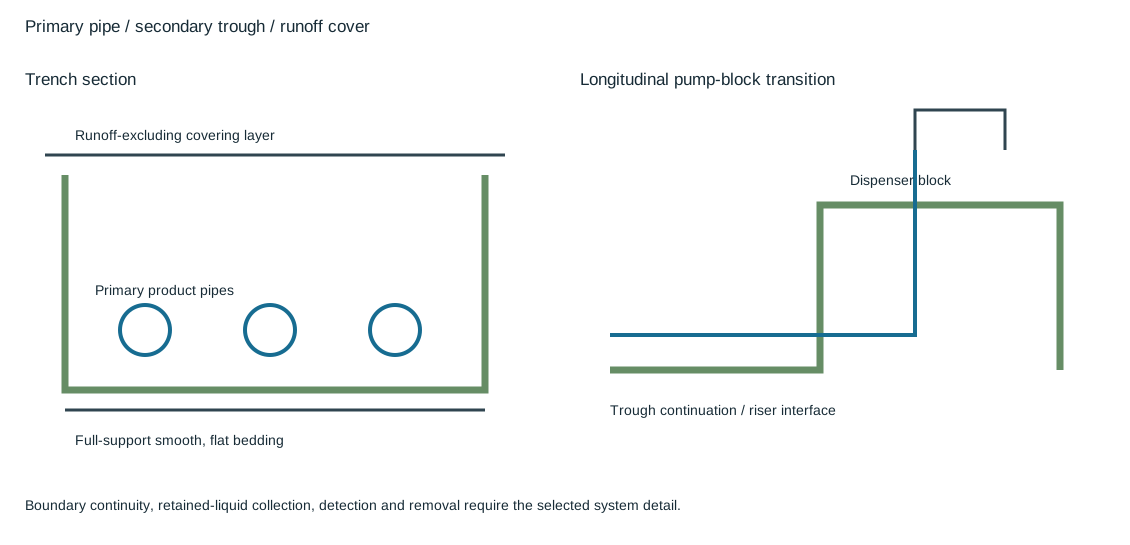
Figure 13.5. The section distinguishes the primary product pipe, the surrounding trough, its full-support bedding and a covering layer that excludes surface runoff. The longitudinal inset follows the trough into the dispenser-block containment as the product pipe rises. No capacity, leak-detection or current containment acceptance is assigned. Structured boundaries and interfaces.
Runoff exclusion and product containment have related but different purposes. Water entering the trough can consume available volume, conceal a leak or complicate inspection and removal. The covering layer addresses that intrusion route. Its joints, edges and penetrations need the selected construction detail. Smooth, flat bedding supports the trough through its length.
Local voids or hard points can change its support and loading even when the product pipe inside it is adequately supported.
The trough must have an identified means of collecting, observing and removing any retained material.
Trace low regions, interconnections, accessible observation points and the receiving destination for removed liquid under the selected system basis.
A continuous-looking channel does not prove drainage, capacity or leak detection.
Keep the containment assessment with the primary piping, its joints and the tank/dispenser transitions.
Do not treat the trench as independent civil work.
Material and corrosion protection also meet at this interface. The represented historical form uses fiberglass troughs and a polypropylene covering sheet. Its sheet thickness and bedding detail are construction-specific rather than universal material or strength criteria. Metal parts in a buried system require their selected protective arrangement, and a containment structure can interfere with the path for cathodic-protection current. A sealed protective boot around a metal flexible connector serves a different local purpose from the surrounding trough.
Verify compatibility, inspectability and protection of the actual parts through materials, external protection and the selected containment basis.
Read a loading arm in both elevations
A loading-rack side elevation locates the separate product risers and arm pivots along the working line. An end elevation then shows how an overhead product route, its vertical connection and the arm's horizontal and vertical reach relate to the vehicle connection and working zone. The same pivot and connection must be identifiable in both views. An arm that reaches a point in one projection can still miss it in the other or pass through an occupied working space.
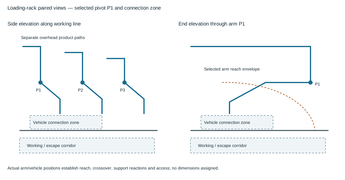
Figure 13.6. The paired views retain overhead product supply, the selected arm pivot and the vehicle connection zone. Dashed arcs denote a reach envelope to be established for the actual arm; their radius is not a certified reach. The working/escape corridor remains separate from the arm connection geometry. Structured paired-view interfaces.
Overhead supply can keep product connections visible while requiring a defined support and access arrangement. A vertical drop changes the elevation of the product path. The loading arm then articulates from its pivot to the selected vehicle interface.
Preserve product segregation through the risers and arms.
Similar arms beside one another do not establish an interchangeable product connection, and common supporting steel does not authorize a common fluid path.
Examine the arm in its stowed, connecting, transfer and disconnected positions against the selected vehicle range.
Adjacent arms need their intended crossover space, while the driver's escape and personnel access routes must remain useful with the arms in those positions.
Include vehicle positioning, coupling handling, overhead obstructions, moving envelopes and the support reactions.
The actual loading arm, nozzle and site information establishes these relationships. Historical nominal dimensions do not certify reach or escape clearance. The consumer hydraulic basis remains attached to the selected connection rather than inferred from the drawing's height.
Product delivery, tank breathing and returned vapor use different paths
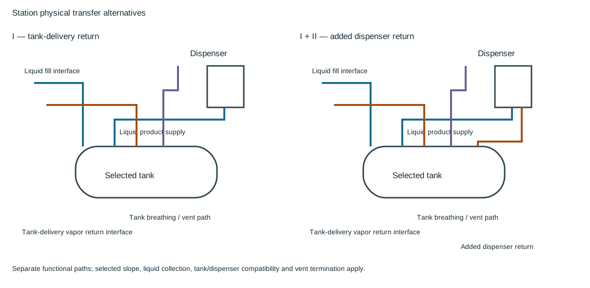
Figure 13.7. Alternative I identifies the liquid fill, product supply, tank vent and tank-delivery vapor-return interfaces. Alternative I + II adds a separate dispenser return to the selected tank connection. They are independent functional alternatives, not instructions to add recovery piping to every station. Vent endpoints are selected-design interfaces, without permission for unrestricted release. Structured transfer alternatives.
Tank-delivery vapor return and dispenser vapor return originate in different transfer activities. The first connects the tank vapor space to the selected delivery interface as liquid enters the tank. The second begins at the dispenser's selected vapor connection and returns through its own branch or manifold to the identified receiving tank connection. A line labeled vapor must not be assumed to serve both functions, or to replace the breathing path, without the actual compatible system design.
Buried horizontal routes and aboveground risers also have different geometric duties. The riser reaches an accessible aboveground connection. The buried route needs its selected slope and collection relationship so retained liquid does not defeat the intended vapor or product path.
Inspect crossovers in section, including fitting envelopes and their effect on slope.
A drawing showing an apparent continuous fall in plan supplies no elevation evidence.
Keep the receiving low point and destination explicit, with the appropriate inspection and liquid-removal basis.
The depicted installation alternatives were developed with composite steel tanks and particular dispenser constructions. Fiberglass-tank piping was described as similar, with the actual tank and dispenser selected by the plans. Similar topology is not automatic material substitution or interface compatibility. Recovery equipment, dispenser fittings, joint construction, vent termination and the applicable emissions/containment requirements need the adopted contemporary basis. These physical paths establish the configuration questions.
They do not establish recovery efficiency, a universal vent-release permission or an operating lineup.
For aircraft fuel, filtration, water separation, draining low points and protecting hose/sample connections with dust caps preserve delivered cleanliness. A jet-fuel material basis admits carbon steel or stainless steel and excludes copper alloys, galvanized iron and cadmium-plated wetted parts. Under that basis, instruments and connectors need the same compatibility review as the pipe. Small-airport fiberglass systems described for other aircraft-fueling uses do not override the stated jet-fuel material rule. Product identity must remain attached to the local selection.