Chapter 14 — Hazardous and cleanliness-sensitive services
Describe the medium and the state that creates the hazard
Material, joints and safeguards must match composition, phase, coincident pressure/temperature, contaminants and surrounding atmosphere during operation, testing, opening and repair. Closed sour piping, air-exposed sulfide deposits and wet restart conditions pose different damage/release mechanisms. Removing oxygen does not itself create a personnel-entry atmosphere. Materials, joints, readiness and condition assessment supply the general methods.
Oxygen compatibility depends on ignition as well as corrosion
Many metals can burn violently once ignited in an oxygen atmosphere. Ignition prevention depends on the energy supplied locally, the material's ignition and combustion behavior, and its ability to dissipate heat. A long smooth pipe and a small valve internal do not present the same problem. Thin elements have less material through which to spread heat. Rough edges, particle impact, friction and turbulent high-velocity regions create local ignition concerns.
Oil, grease and organic residues can ignite and promote combustion of adjacent metal. Dust, scale and weld particles can be accelerated into a fitting or valve. Smooth internal surfaces, rounded edges, removal of contaminants and restraint of local velocities address different parts of that mechanism. Good corrosion resistance alone does not establish oxygen compatibility.
Nonmetallic seals and lubricants require proof for the actual oxygen pressure and temperature. Reducing their volume and surrounding them with metal can improve heat dissipation. These measures do not establish that an unqualified material is suitable.
The following material choices illustrate a specifically restricted dry-gaseous-oxygen design criterion. They apply only where the project adopts that criterion. Its −20°C to +150°C range bounds the application but does not by itself select a material. Within that criterion, carbon steel, specified austenitic stainless steels and selected nickel or copper alloys have different applications.
The carbon-steel account includes exclusion of water condensation and noncorrosive contaminants, rigorous cleaning and protection during shutdown. Its particular in-plot application is limited to operating temperatures below 90°C. The associated pressure–velocity chart identifies a carbon-steel category up to 100°C. That chart category does not remove the narrower in-plot condition. Location, temperature and component duty all remain part of the selection.
Specified austenitic stainless grades can make internal cleanliness easier to maintain. External pitting and chloride stress corrosion remain relevant. Within that specifically adopted criterion, higher-chromium grades and duplex stainless steels shall not be used for the specified oxygen application.
Selected nickel alloys provide improved ignition resistance in critical high-velocity or impingement regions. Their exact composition and external environment still matter. For example, an alloy used for its oxygen behavior can have a separate steam-environment cracking concern. “Nickel alloy” describes a family, not a complete material specification.
Aluminum illustrates the importance of scope. It is excluded within this dry-gas temperature basis because its ignition and combustion behavior can produce severe failure. Its established use in cryogenic oxygen-producing equipment is a different application. A material decision for that equipment cannot be copied into an ordinary gaseous-oxygen line. The ordinary line's prohibition cannot be extended silently to the cryogenic installation.
Calculate the local velocity before applying its material rule
Average velocity uses the design maximum flow and the actual internal area at the section being assessed:
Here is average velocity in m/s. is oxygen volume flow at that section's actual pressure and temperature in m³/s. is internal flow area in m², and is internal diameter in m. A standard-volume flow requires conversion to local conditions before division by installed area can give local velocity. Nominal size is not the measured internal diameter.
Restriction and throttling velocities can exceed the upstream average; evaluate the actual local passage against the material criterion.
Read the pressure–velocity regions with their conditions
Figure 14.1 recreates the two high-pressure curves numerically and retains the separate low-pressure regions. Its horizontal coordinate is pressure in bar(g), meaning gauge pressure. This chart coordinate differs from the absolute pressure needed when a gas-property or standard-to-actual-volume conversion requires an absolute reference.
Before comparing the point, establish local flow and pressure on their respective bases.
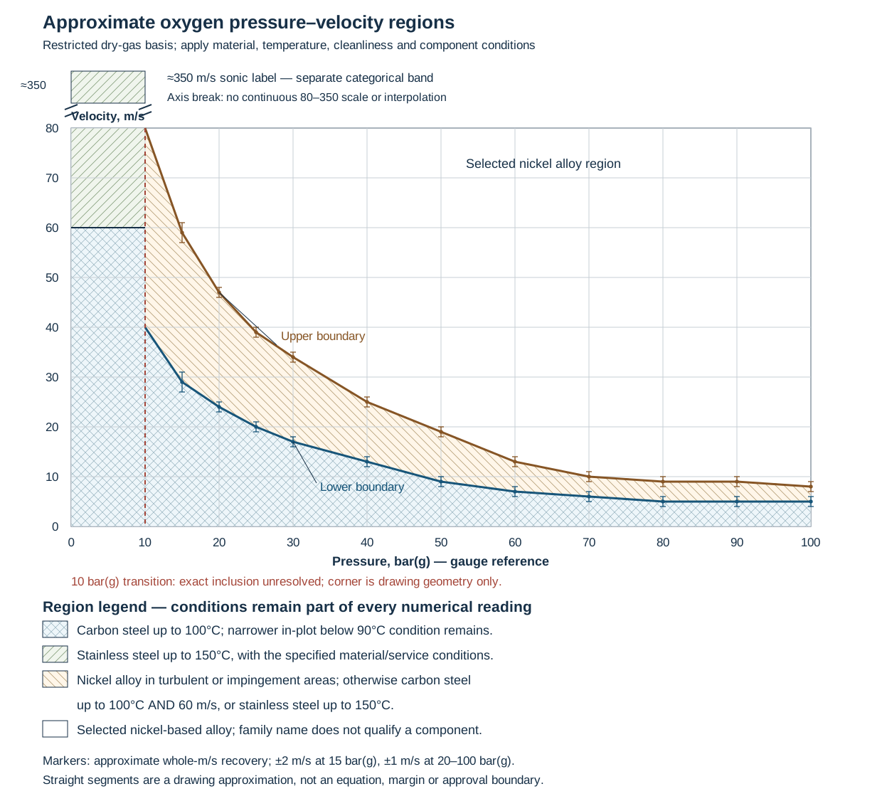
Figure 14.1. Approximate graphical recovery for the specifically adopted dry-gaseous-oxygen criterion. The lower and upper curves define different regions; their legend is part of the method. The low-pressure categories and approximate sonic ordinate are shown separately, with a broken velocity axis. Markers have estimated graphical reading allowances, not operating tolerances or design margins. Recovered numerical data, region conditions and reproducible drawing definition preserve the quantities, uncertainty and discontinuities; drawing implementation reproduces this native figure without a raster background.
At pressures above the approximately 10 bar(g) transition, the crosshatched region below the lower curve is the carbon-steel category up to 100°C. Between the curves, the legend calls for selected nickel-based alloy in turbulent or impingement areas. Otherwise it permits carbon steel up to 100°C and 60 m/s, or specified stainless steel up to 150°C. Above the upper curve is the selected nickel-alloy category.
The two curves are not simply universal carbon-steel and stainless-steel maximum velocities. Component duty and the complete legend distinguish the alternatives. The particular carbon-steel in-plot temperature condition remains below 90°C even where the chart says 100°C.
Left of the approximately 10 bar(g) transition, the chart instead shows carbon steel up to 60 m/s. A separate stainless-steel region extends to the labeled approximate sonic velocity of 350 m/s. That upper label is a categorical endpoint on a broken ordinate. It is not a continuous extension of the 0–80 m/s scale or a universal sonic speed for every oxygen condition. Do not extrapolate either high-pressure curve into this region.
The exact inclusion convention at 10 bar(g) is not established here. Neither the endpoint drawing nor interpolation grants permission at that boundary. The numerical recovery stops at 100 bar(g), where the drawn curves stop.
Table 14.1. Approximate high-pressure boundary readings. Values are in m/s; the ± quantity is an estimated graphical reading allowance at the stated gauge pressure.
| Pressure, bar(g) |
Lower curve, m/s |
Upper curve, m/s |
| 20 |
24 ± 1 |
47 ± 1 |
| 30 |
17 ± 1 |
34 ± 1 |
| 50 |
9 ± 1 |
19 ± 1 |
| 100 |
5 ± 1 |
8 ± 1 |
The structured companion supplies additional sampled ordinates. Whole-m/s reporting and the indicated allowance reflect line width, graphical reading and rounding. The allowance is larger at the steep 15 bar(g) sample. Straight lines between samples reproduce an approximate drawing, not an exact pressure–velocity equation. A point near either curve requires a better-established controlling boundary and treatment of uncertainty. A displayed equality cannot resolve material eligibility.
For a project adopting the same restricted pressure–velocity criterion, its straight-pipe category includes bends only when their radius is at least 5D. Retain the criterion’s pipe-diameter notation D and the radius/diameter convention of its bend detail for this check. The label “long-radius” alone does not establish that geometry. Do not substitute the separately defined internal diameter used in the flow-area calculation without establishing the same measurement basis. Particle-impingement fittings, valve internals and the region downstream of a control valve remain distinct critical regions.
The criterion calls for selected nickel alloys in these critical regions. Within the chart areas allowing carbon or stainless steel, it also describes an alternative using those materials at half the stated velocity limit. These are conditional material/velocity alternatives, not a rule that halving any flow makes any fitting safe. The downstream region extends at least ten nominal pipe diameters under this basis. Actual local geometry must remain consistent with its intended function.
Filters show a related area calculation. The following particular oxygen-filter criterion applies only where a project adopts it. Under this criterion, a filter upstream of control or measuring stations has a maximum 50 μm pore/mesh size. Its maximum entry velocity is 0.2 m/s.
A feed to a low-temperature reaction system containing flammable matter has a finer 10 μm limit. It also has a lower 0.05 m/s entry velocity.
Entry area and pore size are distinct. Filter selection also requires pressure loss, strength and particle-retention performance.
The filter must also be removable without dropping its collected particles into downstream piping. Purge-gas filtration must preserve the downstream cleanliness requirement. A spare dead-ended filter arrangement can create a place for dust to accumulate. Under that adopted filter criterion, spare filters shall not be installed. Maintenance provision should provide access and continuity without reintroducing the contaminant trap that the selection was intended to avoid.
Remove local pockets and preserve the joint orientation

Figure 14.2. Selected oxygen local geometry comparisons.
A tee used only to change direction leaves a capped continuation where particles or cleaning residue can accumulate. A continuous turn removes that unnecessary pocket while retaining the intended path. This comparison belongs to the selected dry-gaseous-oxygen carbon-steel/stainless-steel construction. The bend, branch and local material still need the applicable impingement, pressure–velocity and cleanliness checks described above. Eliminating a pocket does not qualify every elbow material.
The same route places a cathodic-protection insulating flange only in a vertical line section. This avoids particulate deposition that could bridge its insulation. The selected design and materials require their adoption approval and protection against internal sparking from potential differences. A vertical installation addresses the deposition geometry. It does not by itself establish the complete electrical or pressure boundary.
The physical bypass comparison permits a position above the main pipe or in the same horizontal plane. It excludes a position below the pipe. The source-conditioned construction specifies Monel bypass piping above 2,000 kPa gauge design pressure and allows an appropriate integral valve-body bypass. Its usual maximum ¼D notation is not a universal bypass sizing rule.
Actual flow, pressure, material and velocity must establish the selected part. No control architecture follows from the orientation comparison. Structured geometry and conditions preserve these separate physical obligations.
For the remaining dimensional statements, retain each statement's own basis. Ordinary bends in this route use R ≥5D. A separate nickel-base-alloy fitting illustration literally labels an R =1.5D part as short-radius. That historical label does not settle another catalog's radius name.
Successive one-nominal-size reductions have an at-least-1,000 mm statement in the body and a greater-than-1,000 mm figure label. At exactly 1,000 mm, the adopted construction instruction needs resolution. The two statements cannot silently be treated as identical.
Vent orientation is another unresolved distinction. The body describes vertical, straight vents with conditions for unavoidable bends and curved alternatives. The annotated graphic recommends horizontal discharge to a safe location. Before fabrication, resolve the adopted vent configuration, downstream stainless-steel construction and velocity basis. The local pocket, insulating-joint and bypass comparisons do not choose between those vent instructions. Fabrication and Cleanliness and readiness carry the resolved geometry into the inspected installation.
Establish and preserve oxygen cleanliness
Shop precleaning must be preserved through sealed storage and erection; site fit-up or welding can require post-erection cleaning. Select the combined method early enough to provide access and removal paths.
During cleaning planning, select the method early enough to permit temporary spools, access, drains, segregation and removal of cleaning agents.
The agent must be compatible with the item, its contaminants, the downstream process and the personnel/environmental conditions of its use. A residue that is harmless to one cleaning operation can contaminate or poison the receiving process.
Where the precleaned state is preserved and site welding is limited, a specified blow-through with oil-free air can address particles. Brush pigs can supplement this blow-through where appropriate. It is not a substitute for degreasing a system whose cleanliness was lost. Chemical cleaning then needs complete agent removal and drying.
A water-based rinse introduces a moisture state that can produce later rust in carbon steel. Under a particular procedure, residual-air dew point after rinsing and drying must be at least 10°C below minimum service temperature. This moisture criterion does not replace oil or particle checks.
Long transport lines present a particular problem. Cleaning liquid may be difficult to remove completely, and hydrotesting can cause subsequent rust. The selected sequence therefore joins examination, pressure testing, mechanical cleaning, displacement, drying and preservation. A permitted pneumatic alternative changes stored-energy and examination considerations rather than simply saving drying time. Testing and cleaning develops those system methods. Oxygen cleanliness remains an independent requirement after them.
Cleanliness inspection needs accessible evidence and a defined acceptance basis. Direct inspection can use bright white light and ultraviolet methods, together with examination for scale, spatter, fibers and organic residues. Wiping with a clean lint-free cloth or inspection of representative cleaning-fluid effluent can address surfaces that are difficult to view. Indirect inspection compares the effluent with clean unused fluid. Sampling and analysis must represent the parts being accepted. A target used during blow-through gives evidence of carried particles, rather than a complete measurement of oil remaining on every surface.
Under one adopted oxygen-cleanliness basis, allowable oil on metal is 1 g/m². The associated observations show that oil at that loading is not visibly apparent under bright white light and does not produce a detectable finger smear. Visual absence of oil is therefore weaker evidence than meeting the surface-loading limit. The same inspection procedure uses separate fluid-sample criteria: fluorescence can identify oil contamination, and an evaporated sample-residue criterion is expressed in mg/kg. A bulk-fluid concentration is not a surface loading. It cannot be converted into g/m² without a supported sampling, extraction and area relationship.
Preserve caps/seals and closed cleaning/joint-material containers; segregate oxygen tools and materials from oily work. Keep covers until joining and re-establish cleanliness after contamination.
Dry internal weld roots, smooth flow paths and retained cleanliness matter as well as external weld appearance. A clean, completed system awaiting startup needs a defined preservation atmosphere, pressure and duration, with the same controls on the gas's oil, moisture and particles.
Preserve the oxygen design conditions while operating and opening the system
Throttling and isolation are different duties. Under the example’s specifically adopted oxygen-valve criterion, a control valve has selected nickel-alloy body/internals and a downstream high-velocity-compatible section. A separate block valve provides tight shutoff. The control valve is not credited with both duties.
Block valves operate fully open or closed. Pressure equalization precedes opening, and no oxygen flows before ordinary closing. This is a specified operating basis, with separately identified emergency and nitrogen-purge exceptions. An emergency valve needs a protected or remote operating position so its operator is not placed beside the release.
Pressurizing, depressurizing, venting and purging follow the normal oxygen-flow direction under this basis. It excludes back-blowing an installed filter. Clean nitrogen used for purging must remain at higher pressure than the oxygen system at the connection. The connection must prevent oxygen entering the nitrogen network. A low-point dead leg, an unfiltered temporary purge hose or a bypass below the main line can alter contamination behavior. Correct selection of the main pipe does not prevent these changes.
A connection to equipment containing flammable material needs separation during startup and shutdown. The available alternatives include two double-block-and-bleed arrangements in series or a pressurized nitrogen wedge in a section of oxygen piping. Their pressure, valve and vent functions require their own evaluated configuration. A single non-return valve is not a substitute for the selected separation method.
Opening introduces further states. Before oxygen-system inspection, maintenance or repair, the adopted procedure removes oxygen by venting followed by oil-free nitrogen purging. Internal inspection requires complete removal of the relevant item or clean, visible-handled spades at all connections. Personnel entry adds another condition: nitrogen must be replaced with air and ventilation maintained. Oxygen removal and positive separation do not establish an atmosphere suitable for entry.

Figure 14.3. An authored condition map for the scoped oxygen intervention basis. The four panels distinguish operating control, oxygen removal, physical separation for internal work and the additional atmosphere condition for personnel entry. They identify conditions to establish, rather than supply a valve sequence or an entry procedure. Repair and return must restore cleanliness and the applicable component/operating basis; structured condition data retains those distinctions.
Repair/reinstatement must preserve qualified oxygen components, joining and cleanliness, including access for inspection/recleaning before service. Ordinary lubricants, temporary seals or shop handling can invalidate that condition.
Hydrogen selection needs a material envelope as well as a pressure rating
A process-hydrogen class can carry a familiar flange pressure class while adding a separate temperature restriction tied to material and hydrogen partial pressure. Selecting the pressure class alone loses that condition. The material, its specified product and heat-treated condition, the hydrogen exposure and the selected component limits must describe the same intended operating state. A hotter startup, a changed feed or a replacement item can change that state without changing the line's nominal size.
A specifically adopted carbon-steel hydrogen basis refers to the material's API 941 temperature limit at the applicable hydrogen partial pressure. It separately caps its class at 205°C. Its explicit rule takes the lower of those two temperature limits. The 205°C value is a local cap in that basis.
It is not a general carbon-steel hydrogen permission. Meeting it does not remove the need for the material-curve check. The applicable curve must be established for the actual material and exposure before its temperature can enter the comparison.
Keep the two temperature constraints visible
For that selected carbon-steel basis, write the temperature comparison as:
In this equation, is the already established temperature limit from the applicable material curve at the established hydrogen partial pressure. is the separate local class cap. Both quantities are in °C and concern the same selected material/service basis. The intended exposure temperature , also in °C, must satisfy for this temperature comparison. This step does not calculate partial pressure, establish the curve's applicability or demonstrate the adequacy of the complete assembly.
A pressure reference, composition and applicable curve edition are needed wherever the adopted material evaluation requires them. A total line-pressure value, an instrument reading or a flange class does not by itself identify the hydrogen partial-pressure input. For the partial-pressure input:
- Establish the relationship on the adopted assessment basis.
- If it is missing, leave the comparison unresolved.
- Do not infer an acceptable curve temperature from the class cap.
Retain the conditions of the selected material family
The same class portfolio illustrates why upgrading a material name is not a complete envelope calculation. Its hydrogen classes using 1¼Cr–½Mo and 2¼Cr–1Mo specify a 595°C class cap and retain the material-curve reference. Other process classes using those alloys have different stated caps. A limit from a nonhydrogen class cannot replace the hydrogen class's 595°C condition. The 205°C carbon-steel rule and 595°C alloy-family cap remain separate adopted conditions. Neither is a universal ranking of hydrogen resistance.
Other selected hydrogen families use 5Cr–½Mo or 9Cr–1Mo with a 645°C class cap and material-curve reference. Specified austenitic stainless and nickel-alloy families have their own class, product, bolting and component conditions. The ferritic class's curve instruction cannot be transferred into every stainless or nickel-alloy selection by analogy. A higher class temperature also does not raise a lower individual component rating.
For example, a selected 321H family states a 705°C class cap. Its listed gauge-valve item has a 540°C temperature rating. The particular item remains limited by its own applicable pressure–temperature rating.
Product condition and construction details continue below the class heading. Specified normalizing, normalizing and tempering, annealing, hardness, wall selection, joining and any required heat treatment are parts of the material basis. A valve's trim, packing and nonmetallic parts can impose further restrictions. Some of the selected stainless hydrogen classes explicitly exclude free-machining trim.
A body-material match does not remove that local restriction. These examples explain how to inspect the complete adopted class and item notes. They do not provide a replacement catalog or permission to substitute a named alloy.
Small tubing adds a system boundary. A tubing addendum can restrict installation to downstream of the referenced class's block valve. It can specify tube condition and matching fitting parts. It can also give a lower complete tubing-class envelope than an individual connector rating. A downstream location does not make the tubing depressurized while the block valve communicates with the process.
For tubing assessment, include the connected, isolated and intervention states. instrumentation explains the physical isolation and measurement functions. Class and product selection and components and joints retain the detailed material, geometry and fitting-system methods.
Carry the envelope through fabrication, operation and change
Procurement/fabrication must deliver the specified product, heat-treated condition, joining and component limits. A pressure test cannot establish the material-curve limit or qualify altered heat treatment. Hotter duty, changed hydrogen exposure or replacement product reopens the curve/class comparison and affected component/fabrication assessment.
Retain material/condition, applicable curve/edition, established partial-pressure input, temperature/component limits and unresolved assumptions together in records. Existing damage requires condition assessment; this temperature comparison neither predicts deterioration rate nor declares the item undamaged. Joining, readiness and modification preserve the selected state.
Caustic selection follows the temperature the wall can reach
Sodium-hydroxide embrittlement is a stress-corrosion mechanism whose selection basis changes with temperature and concentration.
For caustic selection, establish the temperature the pipe wall can reach, including tracing contact and upset exposure. Do not use only the nominal fluid temperature.
A material and fabrication choice must carry the actual caustic composition, temperature history and joined configuration together.

Figure 14.4. Bounded historical sodium-hydroxide material and treatment regions.
The historical region chart spans 0–50% NaOH and −10 to 130°C. Its percentage convention is not specified.
Before applying the chart to an actual fluid, establish its concentration basis.
The sampled region data and requirements retain approximate curve readings, ±2°C reading envelopes at the samples and ±0.5 percentage-point concentration reading uncertainty. Connected samples reproduce the visible shape. Intersample curvature uncertainty is unquantified, and the drawing does not establish exact inclusion on a boundary.
The three regions describe distinct material/treatment routes:
| Region |
Material account |
Additional treatment in this route |
| A, without tracing |
Carbon steel |
No additional treatment listed in this table |
| A, with tracing |
Carbon steel |
PWHT of welds, including attachments, and cold-formed parts |
| B |
Carbon steel |
PWHT of welds, including attachments, and cold-formed parts |
| C |
Nickel alloys |
No additional treatment listed in this table |
An entry with no listed treatment does not establish complete material or code eligibility. The actual adopted piping class, alloy/product and fabrication basis remain required. Near a recovered boundary, resolve the actual concentration basis and graphical uncertainty before assignment. A traced Region A case still carries PWHT without crossing the curve.
For the adopted PWHT route:
- Avoid cold-formed parts as far as possible.
- Before PWHT, complete all required attachment welds.
That ordering does not permit welding supports to the pipe. The same construction basis prohibits those support welds and places insulation strips between pipe and support.
To avoid hot spots, use the specified spacer construction to separate steam or electric tracing from direct wall-to-wall contact.
Changing the tracing contact can therefore reopen the wall-temperature and fabrication decision even when the fluid composition has not changed.
The associated fabrication route uses GTAW for DN 50 and smaller piping and for the root pass of larger piping. Required PWHT follows its adopted ASME B31.3 basis, with cooling no faster than 100°C/h down to 350°C and the complete cycle recorded. Those local conditions belong with the material, weld procedure and service identification. They are not a universal treatment schedule for nickel alloys or other caustic systems. Material and class selection, Thermal construction, Heat treatment and Engineering records preserve the actual selected condition through supply, fabrication and later changes.
Separate H₂S release hazard from deterioration inside the system
Hydrogen sulfide is toxic, and its atmospheric hazard depends on concentration and duration. Smell is an unreliable protective indication because higher exposure can suppress the sense of smell. Gas can accumulate in low places under poor air movement. Containment, detector coverage, alarms, ventilation and access therefore need a physical basis. An operator's ability to notice an odor is not one.
The process stream and the atmosphere around a release have different concentrations. For an H₂S design procedure using the following categories, the classification selects the extent of special construction provisions. It does not set an atmospheric exposure limit.
Table 14.2. Scoped sour-service classifications.
| Process classification under this basis |
Gas-stream H₂S by volume |
H₂S vapor pressure over a liquid at operating temperature |
| High |
Over 24% |
Over 4.0 psia |
| Moderate |
1% to 24% |
0.1 to 4.0 psia |
| Low |
Below 1% |
Below 0.1 psia |
For mixed-phase streams this procedure generally uses vapor-phase concentration. Pressure, proximity and special applications can change the required treatment. These categories are process-design distinctions, not material immunity or personnel-exposure permissions; structured service data preserves the scope.
A “low” classification can still require a material review. Water, ammonia, salts, acids and other constituents affect corrosion, and local turbulence can increase attack. Ferritic base metal or welds that are too hard can crack in aqueous H₂S environments. Hardness, strength, heat treatment, material family and actual sour conditions interact. A successful alloy at one composition and water state is not evidence for all fluids bearing the same sour-service name.
The scoped fabrication basis distinguishes carbon-steel weld hardness, stronger mechanical-component materials and particular line-pipe applications. It does not provide one universal hardness limit for every item.
For procurement and qualification, retain the adopted material/weld criteria developed in material selection and welding and examination.
Raising strength to reduce wall thickness can introduce a cracking concern that the pressure-only selection missed. Copper-alloy incompatibility, trim suitability and spring/bolting behavior also require service review.
Connections and instruments are containment decisions.
For sour-service connections, minimize unnecessary flanges, unions and small process-filled leads.
A supported instrument bridle can reduce vessel connections and permit isolation for testing, but it introduces weight and thermal-growth requirements. Restricting a small lead can limit a release. Reducing it too far can defeat measurement or make a deposit blockage more likely.
Select the measurement and isolation arrangement together, using instrumentation and connection integrity.
Classify aqueous mechanisms before combining construction requirements
A refinery/gas-plant carbon-steel route assesses the aqueous environment separately for SSC, hydrogen blistering/HIC/SOHIC and carbonate cracking.
For this assessment, establish likely free water, water-phase pH and H₂S, cyanide and carbonate concentrations in mg/kg of water.
These quantities cannot be replaced by H₂S volume concentration in gas, atmospheric exposure categories or the threaded-connection categories in Joint eligibility. The mechanism anticipated or experienced determines which assessment applies.
The following rows retain the historical printed ranges. They assume the environment occurs during normal operation. A short upset enters the assessment only when the mechanism can occur over that short duration. Uncertain duration or mechanism needs materials-engineering assessment.
Without likely free water, the route does not consider the named aqueous mechanism susceptible. This says nothing about unrelated corrosion or other failure modes. Unknown cyanide requires assessment from the actual unit, feed and water-wash history rather than a favorable assumed concentration.
SSC route. Its textual gate is likely water, pH greater than 4.0 and low cyanide. The first printed row begins at 4.0. That equality discrepancy remains unresolved. Conditions more severe in pH/cyanide go to the next mechanism route.
| Water pH |
Cyanide condition, mg/kg water |
H₂S <50 |
H₂S 50–1000 |
H₂S >1000 |
| 4.0–5.4 |
Cyanide has no significance at pH ≤7.5 |
Low |
Moderate |
High |
| 5.5–7.5 |
Cyanide has no significance at pH ≤7.5 |
Low |
Low |
Moderate |
| 7.6–7.9 |
<50 |
Low |
Moderate |
High |
| ≥8.0 |
<20 |
Low |
Moderate |
High |
Hydrogen blistering/HIC/SOHIC route. With likely water and pH/cyanide outside the preceding route, use the following mechanism-specific entries. Under these conditions SSC is independently High, even when the hydrogen-blistering/HIC/SOHIC entry is Moderate.
| Water pH |
Cyanide condition, mg/kg water |
H₂S <50 |
H₂S 50–1000 |
H₂S >1000 |
| <4.0 |
Cyanide has no significance at pH ≤7.5 |
Moderate |
Moderate |
Moderate |
| 7.6–7.9 |
≥50 |
Moderate |
Moderate |
High |
| ≥8.0 |
≥20 |
Moderate |
High |
High |
Carbonate route. Its gate requires likely free water, H₂S greater than 50 mg/kg water and pH ≥7.6. With no likely water or H₂S below 50, it does not consider carbonate susceptibility. Exactly 50 mg/kg is unresolved by those greater-than/less-than statements.
| Water pH |
Carbonate <100 |
100–500 |
501–1000 |
>1000 |
| 7.6–8.3 |
Low |
Low |
Low |
Moderate |
| 8.4–8.9 |
Low |
Low |
Moderate |
High |
| ≥9.0 |
Low |
Moderate |
High |
High |
Carbonate columns are mg/kg of water.
When using these entries:
- Do not silently bridge the printed gaps between pH bins or the 500-to-501 carbonate bins.
- Do not round an uncertain value into a preferred cell or interpolate severity between entries.
- Establish the unresolved condition with the adopted assessment basis.
Severity then maps to a construction obligation for that mechanism:
| Mechanism |
Low |
Moderate |
High |
| SSC |
Normal carbon-steel class, no additional requirement in this route |
Moderate-sour requirements |
Moderate-sour requirements |
| Hydrogen blistering/HIC/SOHIC |
Not applicable in the table |
Moderate-sour requirements |
High-sour requirements |
| Carbonate cracking |
Moderate-sour requirements |
Moderate-sour requirements plus PWHT |
Moderate-sour requirements plus PWHT |
Low carbonate severity therefore still carries a moderate-sour material requirement. A high SSC result does not by itself select the high-sour material set. Concurrent mechanisms can combine obligations. Taking the largest severity word and discarding the individual rows would lose these distinctions.
The moderate-sour set uses:
- Seamless ASTM A106 Grade B or A333 Grade 6 pipe.
- Seamless A234-WPB or A420-WPL6 fittings.
- Or HIC-tested plate where welded carbon-steel pipe/fittings are used.
It specifies NACE MR0103 valve compliance, AISI 316 plus stellite trim, A193-B7/A194-2H bolting and uninsulated flanges. The high-sour set specifies low-sulfur seamless pipe/fittings with 0.010% maximum sulfur and HIC-tested plate for welded products. It specifies the same stated valve compliance/trim and A193-B7M/A194-2HM sour bolting. Additional mitigation requires its materials-engineering basis. These are adopted historical class definitions with their applicable product/testing standards, not current blanket material approval.
Where this table adds PWHT, it includes all shop and field piping welds. Welded piping products also need the specified PWHT or weld-seam normalization during manufacture. That manufacturing duty remains required alongside field fabrication. Structured exact rows, gates and obligations support comparison while Material qualification and Fabrication and treatment establish the selected production basis.
Deposits and air exposure change the outage problem
H₂S can form iron-sulfide deposits in oxygen-deficient equipment. On exposure to air, some deposits oxidize rapidly enough to generate substantial heat and can become an ignition source. Sulfur dioxide is another atmosphere concern. A deposit that was stable inside the operating equipment may therefore create a hazard when the equipment is opened. The amount and location of deposits, moisture state, method of opening and ventilation matter. Water-wetting can reduce rapid combustion under the applicable deposit-control procedure, but does not establish gas-free or entry conditions by itself.
Different solids need different removal methods. Low temperature, high pressure and water favor H₂S hydrate formation. Its decomposition requires a suitable increase in temperature or reduction in pressure. Adding cold water can promote more hydrate rather than dissolve it.
Ammonium bisulfide and ammonium carbonate-related salts have different washing/heating behavior. Treating all deposits as “scale” can therefore choose the wrong remedy.
For deposit control:
- Prevent oxygen ingress where it can form sulfur, accelerate corrosion or create a reactive mixture.
- Where deposition remains credible, make the equipment inspectable and cleanable.
Other shutdown mechanisms also depend on changed conditions. Sensitized austenitic stainless steel with sulfide scale can be exposed to polythionic-acid cracking when moisture and oxygen arrive during shutdown. A selected neutralizing wash is a different protection method from controlling pyrophoric heating. Amine-service cracking can also be influenced by steam-out without the appropriate prior washing. Corrosion management develops mitigation. The intervention plan must identify which mechanism and exposure it controls rather than combine their precautions into one generic purge.
Subatmospheric operation reduces an outward release tendency, but leakage of air inward can create corrosion, deposits or a reactive mixture. It should not be described as an unqualified safe state. Batch steps, relief discharges and shutdown conditions can change H₂S concentration.
For these conditions, consider duration and frequency in addition to normal composition.
The operating state that was infrequent in the original design can become frequent after a process change.
Read the hydrate chart on its pressure scale and fluid basis

Figure 14.5. Historical H₂S hydrate formation regions.
The historical chart has temperature in °F and gauge pressure in psig. Its logarithmic pressure scale runs from 20 to 600 psig. Its temperature domain is 40–90°F. Its recovered boundary runs from approximately 47.5°F at the lower 20 psig edge to 85°F at 300 psig.
It then runs vertically at about 85°F to the 600 psig upper edge. The plotted side at lower temperature or higher pressure is labeled possible hydrate formation; the opposite region is labeled no formation within this chart's basis. The vertical branch matters.
When reading the chart, do not continue the inclined segment above its 300 psig junction.
The recovered vertices and scale preserve a ±0.5°F and ±5% pressure plot-reading envelope. These bounds concern reading the graphic. They do not qualify its thermodynamic model. The text describes H₂S reacting with water.
It does not establish gas composition, water activity, mixture effects, equilibrium convention or an experimental basis for the curve. An actual-fluid assessment must establish those conditions and an applicable adopted method before assigning a process state to a formation region. The “no formation” chart label is not a universal statement about mixed sour gas or every water-containing system.
Use the logarithmic pressure scale within the recovered edges; do not extrapolate or assign precision narrower than the reading envelope. A gauge-pressure chart without its reference basis cannot supply an absolute-pressure model.
Water addition is mechanism-specific. Cold water can worsen the hydrate condition described above. A water-washing method for ammonium salt deposits cannot be transferred to it simply because both deposits obstruct piping.
Condition assessment and Intervention retain the actual deposit/removal/restoration basis.
Keep containment, detection and utility separation effective
A closed vent, drain or relief route removes the immediate local atmospheric-release path, but it must remain compatible with pressure, deposits and drainage. In a bellows relief valve, bellows failure can expose its atmospheric vent to the header contents. In another design, a spring can be vulnerable to sulfide cracking. Component selection and periodic condition assessment therefore support the disposal arrangement. A self-draining outlet and short, accessible inlet reduce some plugging concerns, while relief design establishes the protected cases and backpressure relationships.
Detection layout should follow probable leak sources, wind, occupied areas and ventilation intakes. An enclosure with controlled ventilation can protect people outside while creating a potentially hazardous environment inside. Recirculating outside releases through a ventilation intake can defeat the intended protection. Detector location, distinctive audible/visual alarms, control-room indication and a maintained emergency response capability serve different functions. A detector's presence alone does not establish area coverage or a working protective action.
Temporary utility addition can contaminate an entire utility network if process pressure drives fluid backward.
For a temporary utility connection:
- When the connection is not in use, use the selected positive-disconnection arrangement.
- When adding utility fluid against process pressure, verify the utility pressure near the injection point.
A non-return device, pressure indication and a removable spool solve different parts of that problem. Continuous compatible purges used against instrument plugging need the same backflow assessment. Removing dead legs and abandoned jumpovers can simplify containment, but the retained arrangement must still provide the access and isolation needed for useful maintenance.
LPG protection must include the cold state created by pressure reduction
LPG equipment stores a substantial flammable liquid inventory under pressure. A leak or intentional pressure reduction can produce flashing, cooling and a changing liquid/vapor distribution. The coldest metal condition may occur during filling, removal from service, throttling or relief rather than normal storage. Pressure, temperature, toughness and induced movement therefore belong together.
A vessel-design basis assesses autorefrigeration during a pressure reduction from 100% to 40% of maximum allowable working pressure.
Use actual composition and thermodynamic data to compare the resulting metal condition with its fracture/pressurizing basis. The 100%-to-40% case supplies neither temperature nor a depressurization rate and does not replace local throttling/discharge expansion assessment.
Throttling valves and downstream sections need material suitable for their lowest credible temperatures. Relief piping must accommodate cold contraction, avoid liquid pockets and have appropriate brittle-fracture resistance. The pipe can be adequate in hot service while becoming unsuitable during a cold release. mechanical evaluation and supports and restraints develop the resulting movement/load paths. Normal operating displacement alone does not represent this state.
External conditions remain relevant. Insulation on a vessel colder than ambient dew point can promote retained moisture and shell corrosion if its barrier and protective coating are ineffective. Fire exposure affects joints, bolts, supports and isolation. Bolting above the liquid-cooled region can be vulnerable even when the vessel shell still has liquid cooling.
For external LPG conditions, orient connections and plan shielding/access with credible leak impingement and response in mind.
Reducing the number of joints can improve containment, while eliminating a necessary maintenance break can make later intervention more difficult.
Preserve isolation and relief while the LPG configuration changes
A liquid connection can communicate a large stored inventory to an external failure.
For vessel isolation:
- Locate the required isolation close to its source.
- Add the quick-closing or check function selected for the service.
Manual/automatic shut-in, remote access, fire detection and loss-of-power response are distinct parts of the protective arrangement. Fire or vapor alarms can also warn a dependent operation before the protective action abruptly stops its supply.
A restriction fitting limits flow but is not automatically a shutoff. Instrument restrictions can reduce a release after tubing or a gauge breaks. Fouling can block them, and their pressure/response effects can impair a level-control function. An excess-flow valve closes only if the actual failure flow reaches its required actuation condition. In a transfer installation, reducing adapters or a smaller hose can limit the rupture flow so much that a vehicle's excess-flow valve does not close.
For excess-flow protection, evaluate the whole connected path and required end-of-hose/arm protection. Do not infer protection from the valve's name.
Relief must remain available as items are isolated. A procedure for in-service maintenance uses two full-capacity relief valves. Under that procedure, a multiway or interlocked isolation arrangement can preserve a defined protected path while one valve is serviced. A locked-open alternative needs its actual positions, surveillance and restoration managed under that adopted procedure. Two valves connected through a common blocked header do not provide two independent discharge paths.
Where that common failure is credible, evaluate fire damage, header restriction and the allowed disposal alternatives.
Overfilling and fire are distinct relief demands. A rupture disk used alone can cause uncontrolled depressuring under the scoped LPG basis, which excludes replacing its relief valve with a disk. A disk below a valve can serve a different leakage/corrosion purpose, with provisions to observe pressure between them and maintain the valve's service suitability. Do not transfer the disk's function into a general rule for all gases or vessels.
Water draws, drains and samples are operating releases. An adopted arrangement uses a closed receiving system suitable for full-pressure LPG exposure and the required double-valve/self-closing functions. The discharge line and receiver need a pressure and compatibility basis even when the intended draw is water. Trapped liquid in a hose, valve body or isolated piping section also needs thermal-expansion protection. Utility connections may use a removable/turned spool, or a separately permitted spectacle-blind arrangement for frequent utility use. That alternative is local to LPG; the ammonia practice below prohibits spectacle blinds.
Treat pump startup, transfer and disconnection as different states
An LPG pump seal can lose effective liquid lubrication when fluid flashes across its faces. A properly designed seal arrangement must be supported by startup and operating conditions:
- A full liquid pack.
- Appropriate seal-chamber conditions.
- Adequate flow and a suitable stop sequence.
A pump waiting in solar-heated suction piping can face a different startup condition from one recently operated. Local observation at startup can therefore be valuable even where remote running surveillance is appropriate.
Minimum-flow returns, casing/seal vent returns and low-flow shutdown are different alternatives. A return to the suction vessel can maintain circulation. Switching sources can leave it blocked or connected to the wrong vessel. This can create either a lost protection path or product mixing.
A shutdown device needs the appropriate response/sequence. An abrupt action can introduce a hydraulic transient. Rotating-equipment systems develops pump behavior, while the LPG context explains why these seemingly small operating details can become a containment failure.
For pump transfer and shutdown:
- Coordinate the pump and its source-isolation action.
- Keep remote shutdown available from a location that remains usable in the assessed event.
At the loading connection, a terminal valve can reduce the release during disconnection, while thermal relief and a correctly directed return-vent path address other pressures. Hose/arm protection, grounding/bonding and emergency shutoff depend on the actual transfer assembly and service. Planned cleaning or radiography can also affect fire detectors.
When a permitted temporary bypass is needed:
- Preserve the defined alarm function.
- Restore the protective action under the controlled configuration.
Anhydrous ammonia combines toxic release, cooling and cracking concerns
This basis covers anhydrous-ammonia handling/storage/recovery, with separate rules for aqueous ammonia, refrigeration and transportation. Toxic release, corrosive liquid injury, evaporation cooling and flammability in a suitable mixture/confined release remain credible.
Autorefrigeration can chill a leaking flange, adjoining shell, supports or discharge piping. Liquid ammonia boils near −33°C at atmospheric pressure. The credible cooling case is not limited to that rounded boiling-point value. Evaporation and pool conditions can produce lower temperatures, while an initially warm material can lose its required toughness under sudden local cooling.
For ammonia cooling conditions:
- Select new material for the lowest credible condition.
- Evaluate existing equipment against the temperature it can withstand.
Flexibility must accommodate the contraction and relative movement as well as fire exposure and settlement.
A release model also needs its phase and entrainment basis. Pure ammonia gas is lighter than air. A cold cloud containing fine liquid droplets can have an overall density above that of air and travel downwind. Pressurized nonrefrigerated liquid releases can entrain substantial liquid rather than leave it all in a ground pool. Refrigerated-storage spills can pool differently.
For the release model, describe release location and phase, opening size, liquid head, inventory, surface/containment geometry and weather.
A single buoyancy statement or a stored-volume calculation cannot establish the dispersion boundary.
Carbon and low-alloy steels can be suitable while remaining susceptible to ammonia stress corrosion cracking under contaminated conditions. Air contamination, stress, strength, weld hardness and heat treatment matter. The scoped mitigation guidance describes water addition as protecting the liquid phase, but ammonia's greater volatility can leave the vapor phase with much less water. It describes a 0.2% addition without stating the fraction basis. That percentage cannot be converted into a dosing mass or volume from this account. Neither water addition nor a material's lower strength establishes immunity for every exposed location.
Properly applied stress relief can reduce the cracking concern, but a non-stress-relieved repair in an otherwise treated item changes the local basis. Existing missed cracks or an inadequate previous treatment are different deficiencies. Inspection should address the likely internal weld locations and crack mechanism, rather than infer adequacy from a pressure test or average wall thickness. Joining and examination and inspection planning develop those methods.
The ammonia guidance emphasizes wet fluorescent magnetic-particle examination for its steel SCC problem. Penetrant or dry magnetic-particle observations can miss relevant cracks. That scoped choice does not imply magnetic-particle suitability for every material family.
Keep ammonia connections, protection and maintenance compatible
Copper, silver, zinc and certain other materials/alloys are incompatible with ammonia under the stated material basis. Its elastomer rules exclude Viton. A chlorine seal accepted later in this chapter does not become an ammonia seal by analogy. Body, trim, packing, gasket and coating selection all belong to the service review.
For the adopted ammonia piping basis:
- Minimize flanges and provide confined joint forms.
- Where leakage could impinge directly on a shell and chill it, consider shields.
Small branches carry a release and vibration concern as well as a pressure load. The scoped arrangement reserves small branches for auxiliary duty with root isolation, appropriate joining and support. Branches must accommodate the cyclic service and remain protected from external damage. A fully lugged wafer valve and a welded small-valve bonnet solve particular fire/joint issues under this basis. Their use still needs the complete material and functional review.
The ammonia practice excludes spectacle blinds. It does not treat their convenience as sufficient justification for the additional exposed joint and personnel-intervention concerns. Positive isolation must instead be established with the applicable accepted configuration, including removable/turned-spool utility separation where appropriate. Utility pressure must exceed process pressure at an active injection point under that arrangement. The disconnected state prevents ammonia entering the common utility later. Do not copy the separately permitted LPG spectacle-blind alternative into ammonia service.
Sample and draw-off connections need a contained destination, a usable operating position and the specified self-closing protection.
For sample and draw-off connections, place the outlet so a leak does not impinge on the shell or supports.
A fresh-sample flushing arrangement must remain compatible with the enclosure, vent and receiving system. A convenient uncontained sample beside the vessel defeats those functions even if the root valve is correctly rated.
Ammonia overpressure protection includes overfilling, fire, pump shutoff and trapped-liquid expansion. Closed relief piping must drain without traps and accommodate chilling, contraction and backpressure from simultaneous releases.
Where their combination can deposit ammonium salts and plug the shared route, separate ammonia from H₂S or CO₂.
A line that safely contains one release can lose its disposal function when chemically incompatible streams meet.
Where the governing basis permits atmospheric relief, its dispersion, liquid carryover, drainage and independent stack support need evaluation. Atmospheric relief is not the default substitute for a difficult closed-system design. Covers that stick, freeze or obstruct opening can create backpressure. Redundant full-capacity relief and the applicable maintained-open isolation arrangement can permit valve work while preserving protection. Pressure protection develops sizing and system alternatives. The ammonia-specific composition, cooling and deposition cases remain inputs.
Design water application around the phase and location
Water fog can absorb and dilute an ammonia vapor cloud. Water directed onto a liquid-ammonia pool can add heat and cause rapid boiling. Direct application to already chilled nozzles or other components can also worsen the fracture concern. “Provide water” is therefore an incomplete protection decision. Nozzle location, spray pattern, wind, accessible operating position, simultaneous water demand and the location of liquid/metal exposure must be evaluated together.
Fixed or remotely operated fog can be useful where a manually positioned downwind monitor would be inaccessible in the assessed release. This is a trade between operating reach and the added installation/maintenance duty. The liquid's large expansion on vaporization and the dependence of absorption on water temperature reinforce the need for phase-specific assessment. The qualitative fog benefit is not a scrubber-capacity calculation.
Fire cooling of an ammonia-containing vessel addresses another heat input. Its insulation/weathercover, liquid level, neighboring hydrocarbons and exposed connections affect the response.
Keep fire cooling, vapor absorption and liquid-pool treatment separate; protective/isolation equipment must remain accessible in their assessed release conditions.
Chlorine material compatibility changes when moisture enters
This chlorine account covers commercial cylinders and containers of one-ton capacity or smaller, their chlorinators and associated piping. Bulk rail, road and barge transport has a separate scope. Chlorine is nonflammable but reactive and can support combustion. It can react dangerously with hydrogen, hydrocarbons, ammonia and other substances. Its gaseous release is heavier than air. Liquid releases also produce aerosol and vapor whose movement depends on weather, release rate and local terrain/ventilation.
Dry chlorine at room temperature can be handled by materials that will perform poorly when the medium becomes wet or hot. Frequent container replacement exposes the internals to atmospheric moisture. Corrosion products from a nominally compatible dry-service steel can then foul the chlorinator. Capping an unused pigtail and keeping a maintained dry state have a direct operating purpose, rather than merely improving housekeeping.
Selected nickel-alloy piping/tubing and compatible seals can suit the scoped chlorine system. Only a limited range of alloys tolerates continuously wet chlorine. Nonmetallic piping such as PVC may instead be suitable for a continuously wet chlorinated-water section. That choice does not authorize PVC in every dry, pressurized chlorine segment.
Similarly, a seal accepted for chlorine can be excluded for ammonia. Materials explains evaluation of a complete material/joint system. The local medium and state determine the applicable compatibility claim.
For chlorine piping, avoid unneeded joints and protect accessible aboveground piping against mechanical damage.
Container connection parts differ from ordinary downstream joints. The adopted small-piping basis excludes unions in straight chlorine service. It retains separately specified container, pigtail and instrument connections. A general seal-welding instruction must preserve those exceptions. Keep the joint form appropriate for changing containers without expanding the number of ordinary leak points.
Liquid chlorine has a large thermal-expansion effect when trapped and warmed. Self-draining geometry and the isolation arrangement should avoid creating a liquid-filled locked section. Container temperature also matters when units are manifolded. A warm container can transfer chlorine toward a colder one. If the colder unit becomes liquid-full and is then isolated, later warming can create severe pressure. A capacity improvement through manifolding therefore changes containment and operating conditions as well as available flow.
Match withdrawal and feed architecture to demand
A vertical small cylinder supplies gas in its intended upright condition. A horizontal one-ton container has separately oriented gas and liquid outlets. Changing that orientation can change the withdrawn phase. The downstream chlorinator ordinarily needs gas, and liquid carryover can damage its components. Pressure reduction, appropriate heating/tracing or a designed liquid trap can address a specified carryover case, but their temperature and containment consequences require evaluation.
A vacuum regulator at the container minimizes the length of pressurized feed piping under this arrangement. Higher-demand applications may need a pressure–vacuum configuration.
For that configuration, keep its pressurized portion as limited as the evaluated system permits.
The vacuum/pressure boundary governs leak behavior and testing, so it must remain visible in the design and actual installation.
For a preliminary withdrawal comparison, the small-container guidance uses conditions near 70°F with 35 psig backpressure. Without frosting, its approximate dependable continuous gas rates are 15 lb/h from a one-ton container and 1.75 lb/h from a 150-lb cylinder. These are conditional rates, not the contained inventory divided by any chosen delivery time. These conditional withdrawal rates do not select a manifold or establish standby duty, delivered temperature or feed-equipment capacity.
Containers connected together must meet the evaluated common-temperature and phase conditions. An evaporator is another architecture, rather than an extra container with the same operating behavior. Protection, access, monitoring and the receiving chlorinator need to match the selected means of producing gas.
For package layout, place the package and enclosure so required observation and maintenance do not demand entering a probable release area.
Keep chlorine testing, purging and collection distinct
Fabrication/cleaning must exclude incompatible oils, grease, sealants and reactive contamination. A testing medium introduces its own state. Under the scoped chlorine procedure, vacuum-feed piping can use a nitrogen pressure/leak test. Pressurized chlorine-feed piping has a hydrostatic-test basis.
Nonmetallic material limits may require a different test condition. After water testing, complete cleaning and drying before chlorine introduction are essential. Otherwise the test creates the moisture-driven corrosion problem that the material selection sought to avoid.
A chlorine procedure adopts a −40°F (−40°C) dew point after cleaning and drying. For that procedure, verify the measurement on its specified pressure/reference basis.
The temperature alone does not define the sampling condition or justify importing the separate oxygen drying margin.
Before repair, isolate the chlorine source and remove chlorine through the adopted purge and receiving system. Chlorine-containing purge gas can be absorbed in a specified alkaline collection arrangement. Its chemical quantity, water inventory, temperature, gas loading and disposal conditions must be established. A weighted hose alone does not establish absorber adequacy. The neutralized or chlorinated liquid must not be sent indiscriminately into a hydrocarbon-bearing drain where reaction and corrosion can occur. Drain architecture provides the collection/segregation framework.
Container leak intervention is specialized work for trained, equipped responders using the correct cylinder or one-ton-container repair system. The release phase matters. A liquid opening can release much more chlorine than a gas opening. This explains why container orientation belongs in both the normal hookup and the prepared response plan. It does not supply a general instruction to move or rotate a damaged container. Container condition, access and the trained response basis govern the intervention.
Water used to direct or absorb a gas cloud has a different effect from water applied at a leak or a liquid-chlorine pool. Moisture at the opening can form corrosive products and enlarge the leak.
For chlorine collection, keep liquid chlorine out of drains and provide a compatible collected-water destination.
Fire exposure introduces the container's fusible-plug release mechanism, which differs from a conventional spring relief valve. Location, protection from hydrocarbon drainage, heat exposure, traffic and reliable container restraint therefore help prevent a large toxic release as well as ordinary handling damage.
Keep the sample port, container and enclosure distinct
An anhydrous-ammonia residue sample can be collected within an enclosure that surrounds the bottle and its dip-tube entry. The sample path enters through a sealed penetration. The bottle rests on a screen above an integral funnel. A viewing window allows observation with the door closed.
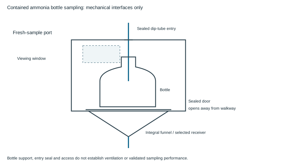
Figure 14.6. The section identifies the sealed dip-tube entry, bottle support, viewing window, door and collection outlet. It represents the mechanical containment/access arrangement only. Ventilation and the selected receiving system require their own demonstrated basis. Structured enclosure roles.
Locate the sample connection and dip tube to limit stale inventory and sample loss; no allowable length is supplied here. The entry seal, tubing connector and bottle position must fit together so the sample does not miss the container or escape through the enclosure penetration.
For the selected bottle and handling task, size and orient the door away from the walkway in this arrangement.
The collection outlet needs an identified compatible closed receiver or another specifically accepted destination away from work areas. A funnel is not a disposal system, and an enclosure does not establish capture efficiency or ventilation adequacy. Keep bottle replacement, cleaning and component release under the adopted sampling and intervention procedure.
Identify separation by the actual hardware and state
A removed or turned flanged spool leaves different fixed faces from a spectacle blank inserted between flanges. In the disconnected-spool comparison, the removable piece is out of the connecting position and the process-side opening has its selected blind flange. In the blanked comparison, the solid part of the spectacle device occupies the joint. The second is an installed closure. The first is a disconnection with a separately identified closure. The existence of either part on a drawing does not establish its actual separating state.
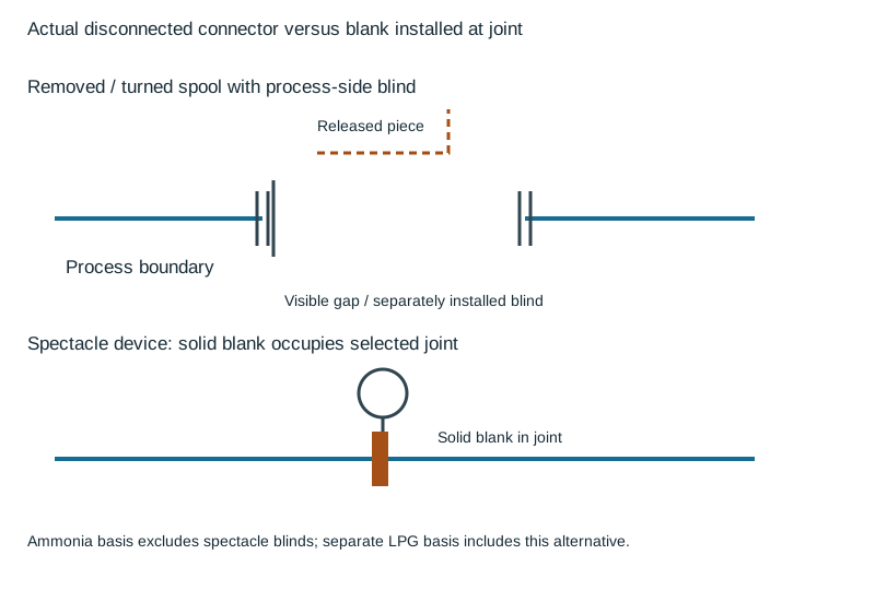
Figure 14.7. The sketches identify the released connector, fixed joint faces and process-side blind flange, or the solid blank in the joint. They omit the connected injection system and its operating sequence. Structured closure alternatives and service eligibility.
The anhydrous-ammonia basis excludes spectacle blinds and retains a removed/turned-spool arrangement with a blind flange on the process-side connection. The separate LPG basis includes both turn-spool and spectacle-blank alternatives. For the selected hardware, keep that service distinction.
Container orientation establishes the selected withdrawn phase
A small chlorine cylinder supplies gas in its intended upright position. A horizontal one-ton container has vertically aligned outlets at one end. The upper outlet serves gas withdrawal, and the lower outlet serves liquid.
For the connection drawing and actual installation, maintain the selected container orientation and outlet identity.
A generic container symbol with one unqualified line conceals that phase distinction.
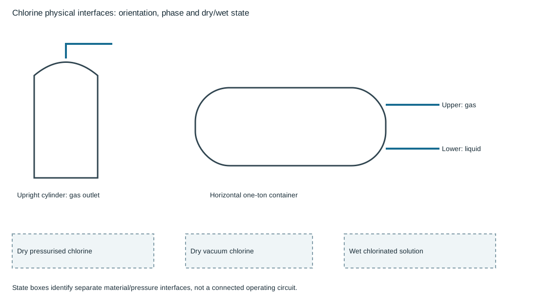
Figure 14.8. The drawings retain gas versus liquid outlet identity and the dry pressurized, dry vacuum and wet-solution material interfaces. The dry-to-wet boundary is a separately evaluated equipment interface, not permission to connect the sketched regions directly. No water-eductor, operating-control or protective-check circuit is specified. Structured container and state interfaces.
A container-mounted vacuum arrangement can reduce the length of pressurized chlorine piping. A separate pressure/vacuum arrangement retains a pressurized segment before the vacuum boundary.
For connection design, treat these as different physical assemblies with their actual detachable connections, support and moisture-exclusion needs.
Container changes expose the connection to atmospheric moisture, so capping unused pigtails and preserving the required dry condition remain part of the mechanical interface.
Dry chlorine piping and continuously wet chlorinated-solution piping need different material and joint evaluations. A material suitable for the wet receiving section does not become suitable for dry pressurized chlorine upstream.
For material and joint evaluation, keep the actual gas-to-solution interface, phase and pressure state visible.
The receiving destination and regulator vent termination require the selected package and facility basis. Conflicting vent-location details cannot be resolved by assuming one universally safe endpoint.
Retain the chemical inventory basis before using an absorption quantity
A chlorine absorption reference pairs a chlorine inventory with either sodium hydroxide and water or sodium carbonate and water. The two alkalis are alternatives, not quantities to add together. Chemical identity, mass units and water-volume units must remain attached to every row.
| Chlorine inventory, lb net |
NaOH, lb |
Water with NaOH, gal |
Na₂CO₃, lb |
Water with Na₂CO₃, gal |
| 100 |
125 |
40 |
30 — unresolved use hold |
100 |
| 150 |
188 |
60 |
430 |
150 |
| 2000 |
2500 |
800 |
6000 |
2000 |
The literal 30-lb sodium-carbonate entry for 100 lb of chlorine is inconsistent with the inventory relationship in the 430-lb and 6000-lb rows. It is retained without a guessed correction. Hold use of this table as an adopted absorption-sizing or preparation basis until its chemical/inventory quantities are validated. Do not interpolate between its rows or infer a scaling rule that silently repairs the discrepancy. Structured literal quantities and use hold.
Even a validated alkali quantity would not complete an absorber design. Gas-loading rate, contacting arrangement, temperature rise, solution condition, receiving capacity and final collected-liquid disposition remain necessary inputs. A stock of alkali and water does not establish effective absorption of a release.
Keep the collected liquid out of unevaluated hydrocarbon-bearing drains.