# Piping Engineering Knowledge
## Contents
- [Defining the piping system and its engineering basis](#chapter-c01)
- [Materials, piping classes and procurement requirements](#chapter-c02)
- [Components and pressure-retaining joints](#chapter-c03)
- [Plant arrangement, access and constructibility](#chapter-c04)
- [Rotating equipment and its piping systems](#chapter-c05)
- [Vessels, heaters, exchangers and storage](#chapter-c06)
- [Branches, small-bore connections, vents and drains](#chapter-c07)
- [Instrumentation, measurement and control systems](#chapter-c22)
- [Pressure design, relief and depressurization](#chapter-c08)
- [Flexibility, loads and vibration](#chapter-c09)
- [Support and restraint decisions across installation, testing, operation and maintenance](#chapter-c10)
- [Buried piping, pipelines and offshore interfaces](#chapter-c11)
- [Utility and service system architecture](#chapter-c12)
- [Hazardous and cleanliness-sensitive services](#chapter-c13)
- [Insulation, tracing and thermal protection](#chapter-c14)
- [Coatings and corrosion management](#chapter-c15)
- [Welding, heat treatment and examination](#chapter-c16)
- [Fabrication and construction of the installation](#chapter-c17)
- [Examination, pressure testing, cleaning and readiness](#chapter-c18)
- [Operating integrity, inspection and maintenance](#chapter-c19)
- [Repair, hot tapping and modification](#chapter-c20)
- [Engineering records, human factors and lifecycle decisions](#chapter-c21)
# Chapter 1 — Defining the piping system and its engineering basis
## Define the connected equipment and active paths
For a vessel-to-pump suction system, pressure available at the pump depends on vessel liquid level and surface pressure, connecting elevations, fluid condition and resistance along the active path. The line boundary on a drawing does not end these hydraulic relationships or the movement transmitted through equipment nozzles.
A valve's required function can be throttling, blocking during an operating change or specified isolation. Its name and nominal rating do not establish that function. Likewise, a temperature indication does not establish a protective response. Define these functions for the relevant configurations before selecting [components](#chapter-c03) or [measurement and control arrangements](#chapter-c22).
## Match fluid condition to the arrangement
A two-phase stream divided between parallel exchangers can deliver different liquid and vapor fractions to each exchanger. Liquid momentum and the resistance offered to vapor affect the split. Equal pipe sizes do not establish equal phase distribution. Evaluate the incoming approach, branch directions, elevations, resistances and which equipment paths operate together against the required phase distribution. Unequal mixtures can change exchanger pressure losses and heat-transfer duties. [Exchanger and reboiler arrangements](#chapter-c06) develops the physical alternatives.
Retain composition, contaminants and credible service changes in the materials basis. Cooling-water constituents can affect alloy choice; sour constituents require their particular materials and intervention provisions. Low-temperature conditions can introduce failure concerns absent in normal warm service. See [materials and piping classes](#chapter-c02) and [hazardous and cleanliness-sensitive services](#chapter-c13).
Associate flow rate, phase, density and temperature with the condition in which they apply. Maximum flow need not occur at maximum temperature, and a stream can change phase within its operating envelope. Unrelated maxima can conceal the combination that governs equipment performance or pressure generation.
## Include elevation in the pressure basis
Pressure in a connected stationary liquid increases with vertical depth and density. Horizontal route length does not add static head. A pressure indication at one elevation therefore does not establish pressure elsewhere in the system.
During filling or testing, a high-point gauge can conceal excessive low-point pressure. Test-liquid density changes both the pressure difference and the weight carried by supports. [Test-boundary pressure limits](#c18-pressure-method) and [support and restraint decisions](#chapter-c10) apply these constraints. Elevation alone establishes no permissible test pressure or component adequacy.
For flowing service, combine elevation with equipment pressure generation and resistance. [Pump suction and duty evaluation](#chapter-c05) also requires vessel level, surface pressure and the fluid condition.
## Flowing loss begins with the bore and the fluid condition
Include both flowing resistance and elevation in the pump-suction pressure balance.
Carry the flowing loss into the [suction and available-head evaluation](#chapter-c05). Use the actual vessel level, surface pressure and liquid vapor pressure.
The method here assumes a circular, fully filled pipe. It also assumes that density and viscosity remain constant along the evaluated length. It does not model changing-density gas flow, phase change, two-phase distribution, water hammer or a transient operating change.
When bore or conditions differ, evaluate separate segments. Adding their lengths while retaining one diameter can conceal the controlling loss.
Let $Q$ be volumetric flow in cubic meters per second, $d_i$ the actual inside diameter in meters and $v$ mean velocity in meters per second. Continuity gives
$$
v=\frac{4Q}{\pi d_i^2},\qquad
\mathrm{Re}=\frac{\rho v d_i}{\mu}=\frac{v d_i}{\nu},
$$
where $\rho$ is density in kilograms per cubic meter and $\mu$ is dynamic viscosity in pascal-seconds. The kinematic viscosity is $\nu=\mu/\rho$, in square meters per second.
Before using the first expression, divide flow stated in cubic meters per hour by 3600.
Nominal pipe size identifies a size series. Wall thickness and lining determine the bore. Using DN as the inside diameter changes velocity, Reynolds number and the loss calculation together.
The flow regime determines how a friction lookup may be used. Laminar flow is expected below Re 2300 and turbulent flow above Re 4000. Between them, the flow can switch regime and pressure loss can change by a factor of three or more.
Do not interpolate a single stable factor through this transition interval. Before treating a nominal factor as a repeatable pressure-loss prediction, resolve the operating regime and its consequences.
## Roughness and factor convention travel with the lookup
A roughness chart supplies a material and diameter relation for the friction chart. Its nominal diameter index is a separate convention from $d_i$ in Reynolds number. For the historical chart basis illustrated here, the printed absolute roughness labels are:
- 50 μm for carbon steel/alloy;
- 120 μm for bitumen-lined pipe;
- 260 μm for cast iron;
- 1500 μm for cement-lined pipe.
A separate note gives 50 μm for **smooth cement-lined pipe of DN 400 and larger**. The cement categories therefore cannot be collapsed into one material permission. The labels do not characterize every new, corroded or fouled pipe of that material.
For the installed pipe, confirm the material, lining, surface condition and applicable roughness basis.
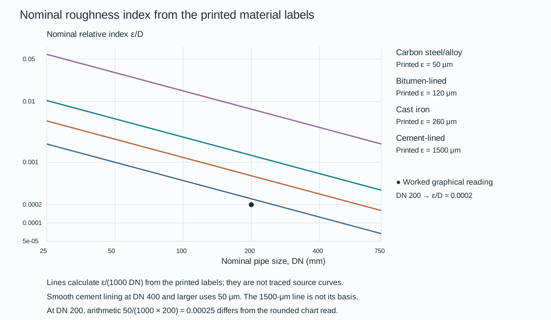
*Figure 1.1. A reproducible arithmetic illustration of the nominal roughness index from selected printed labels. The lines use ε/(1000 DN), with ε in μm and DN in mm. They do not digitize every material curve.*
*The point preserves the worked graphical reading for DN 200 carbon steel/alloy. At that size the label arithmetic gives 0.00025, while the worked chart reading uses approximately 0.0002. Those levels of precision remain distinct.*
For the worked graphical route, DN 200 carbon steel/alloy gives relative roughness approximately 0.0002. At Re 70,000 the stated friction reading is $\lambda=0.0205$. A wider recovered lookup below supplies six solid roughness curves over approximately Re 50,000–50 million. Each saved curve has original graphical samples. The original dashed example projection is distinguished from the solid curve family.
The textual worked reading remains separate from a rounded trace reading. They are not forced to coincide exactly.
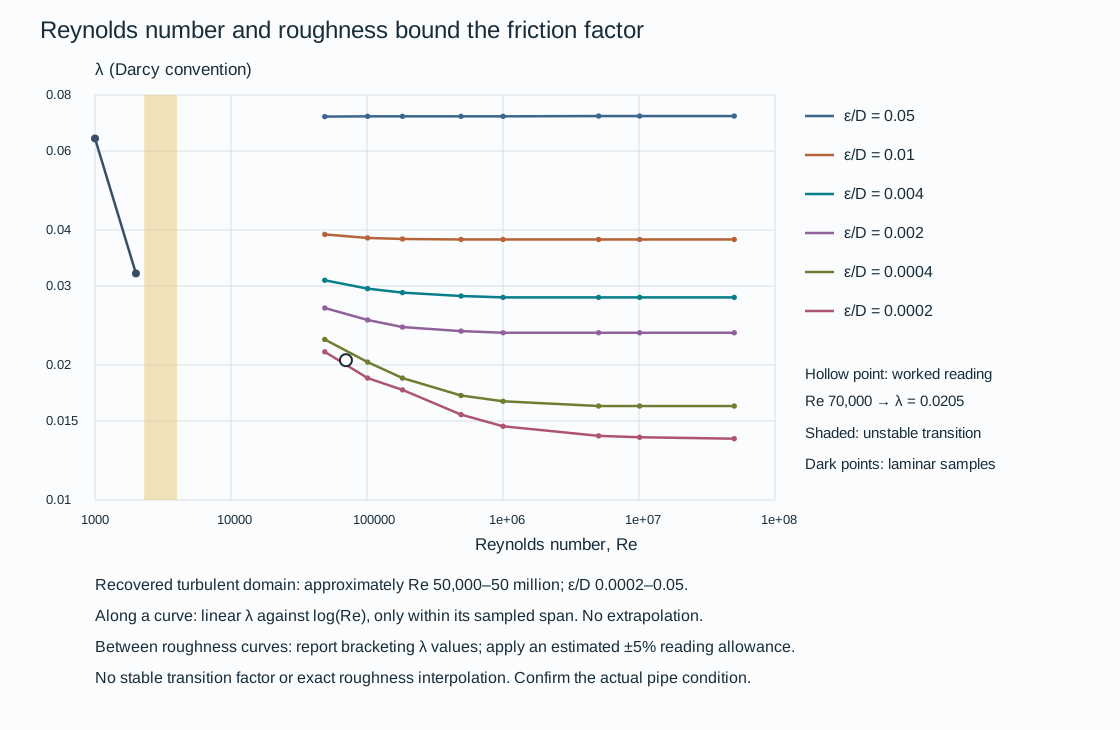
*Figure 1.2. Approximate graphical recovery for relative roughness 0.0002, 0.0004, 0.002, 0.004, 0.01 and 0.05. Along each recovered curve, use straight joining of λ against log(Re) only between saved samples. For a roughness between two curves, report the two bounding factors instead of claiming an exact interpolation.*
*An author-estimated ±5% allowance expresses graphical reading resolution, not a statistical confidence bound or a design margin. No extrapolation or transition factor is supplied. Two laminar graphical points illustrate the separate regime.*
For example, the nominal index from the cast-iron label at DN 100 is $260/(1000\times100)=0.0026$. At Re 100,000 that lies between the 0.002 and 0.004 curves, which give approximately λ 0.0252 and 0.0296. The lookup therefore supports a factor bracket, about 0.0239–0.0311 when the estimated graphical allowance is included.
The pressure-loss equation fixes the factor convention:
$$
\Delta p=\lambda\frac{L}{d_i}\frac{\rho v^2}{2},\qquad
\Delta h=\frac{\Delta p}{\rho g}
=\lambda\frac{L}{d_i}\frac{v^2}{2g}.
$$
In these equations, $\Delta p$ is frictional pressure loss in pascals and $L$ is total equivalent length in meters. The quantity $\Delta h$ is loss in meters of the flowing liquid. The λ convention is the Darcy factor. If a calculation supplies a Fanning factor $f_F$, the corresponding λ is $4f_F$.
Inserting $f_F$ directly into the displayed equation understates the loss by four. Before transferring a factor from another representation, identify the convention from the equation and accompanying data.
## Equivalent length belongs to the selected component state
For the adopted procedure, total equivalent length is straight-pipe length plus the equivalent lengths of fittings and fully open valves on the active path.
The table uses **nominal diameter $D$**, expressed in meters when calculating $L_e$. The loss equation retains the actual bore $d_i$. Selected entries illustrate the distinction:
| Component and state | Equivalent length |
|---|---:|
| Fully open gate valve, standard bore | $13D$ |
| Fully open ball valve, reduced bore, DN 40 and smaller | $65D$ |
| Fully open ball valve, reduced bore, DN 50 and larger | $45D$ |
| Equal tee, flow straight through | $20D$ |
| Equal tee, flow through side outlet | $65D$ |
| 90° elbow, radius $1.5D$ | $20D$ |
| 45° elbow, radius $1.5D$ | $16D$ |
The [complete structured equivalent-length table](assets/C01/c01-equivalent-lengths.json) preserves the remaining component patterns and size conditions. These values belong to this adopted procedure. An inline instrument or equipment item needs its own manufacturer loss data.
Use manufacturer data for critical losses. Avoid counting a loss through both an equivalent length and a separate pressure-loss term.
The fully open valve entries do not describe a partially closed valve. A changed component position or a dirty strainer can invalidate the loss basis even while nominal pipe size remains unchanged.
## A preliminary liquid lookup narrows the alternatives
The flow–velocity relation can compare candidate bores before a final pressure-loss evaluation. The native plot below uses a selected printed schedule basis. It uses DN 50, 80, 100 and 150 in Schedule 40, and DN 200 in Schedule 30. Its inside diameters are respectively 52.48, 77.92, 102.30, 154.10 and 205.0 mm.
At 100 m³/h, for example, the 154.10-mm bore gives approximately 1.49 m/s. The 205.0-mm bore gives approximately 0.842 m/s. Before transferring either result to a system calculation, select the actual pipe wall and lining.

*Figure 1.3. Calculated continuity relationships for explicitly stated printed bores, with flow in m³/h and velocity in m/s. The [structured dimensions, graphical readings and worked calculation](assets/C01/c01-hydraulics.json), and [reproducible drawing implementation](assets/C01/c01-hydraulics.draw.py), preserve the distinctions between tabulated dimensions, recovered chart readings and hypothetical inputs.*
One preliminary liquid-sizing procedure presents three flow panels: 0.1–10, 10–1000 and 1000–10,000 m³/h. Its suction and discharge areas use water at 20°C and pressure loss per 100 m: 0.034–0.083 bar for suction and 0.149–0.627 bar for discharge. These are pressure-gradient bands, not pump inlet or discharge pressures.
Within that procedure, more than one size can lie in the indicated area. In that case, the smaller size is selected for lines up to 100 m and the larger for longer lines. The local procedure is not a universal size selection rule. Preserve it with its water basis.
The preliminary interconnecting-liquid velocity band is 0.5–5 m/s in this basis. It excludes sludge, slurry, erosive fluids and two-phase flow. Being inside the band does not establish final acceptability. Under the adopted project conditions, evaluation is still needed for:
- Allowable pressure loss;
- Surge, erosion and vibration;
- Solids settling and viscosity changes;
- Mechanical strength and the equipment duty.
The related carbon-steel water-loss charts cover 1–10, 10–300 and 300–10,000 m³/h. Their first panel is headed **2°C**. The continuation panels are headed **20°C**. The discrepancy prevents treating the three panels as a single calibrated temperature basis. The middle-panel readings below remain attached to its 20°C heading. No temperature correction or whole-range join is supplied.
The charts identify DN curves, but do not state their bore and roughness numerically. Dimensions from the separate continuity table cannot establish those hidden chart inputs.

*Figure 1.4. Recovered middle-panel DN 100, 150 and 200 curves. Samples include intersections with the stated preliminary suction and discharge gradient bands. Straight joins in log(flow)–log(gradient) space provide a bounded graphical lookup within each curve's saved span. They do not fit a physical loss equation or reveal the unstated bore. No extrapolation, interpolation between nominal sizes or first/third-panel join is supplied. The plotted bars express an author-estimated ±15% pressure-gradient reading allowance, not acceptance tolerances.*
As a worked graphical comparison, take 130 m³/h on that middle panel. The recovered gradients are approximately 1.63 bar per 100 m for DN 100, 0.211 for DN 150 and 0.0497 for DN 200. Including the estimated reading allowance gives about 1.39–1.88, 0.180–0.243 and 0.0422–0.0572 bar per 100 m respectively.
The DN 100 result is above both preliminary bands. DN 150 lies within the adopted discharge band and DN 200 within its suction band.
This comparison is conditional on the chart's carbon-steel-water basis and shows which alternatives merit further evaluation. It does not select a final size for another liquid or establish available suction head. A nominal straight-pipe gradient multiplied by actual straight length does not include component, instrument or equipment losses. Those losses are included only if their adopted representations are added separately.
Changing the flow at a retained DN is a different operation from comparing DNs at one flow. On the recovered DN 150 curve, about 58.8 m³/h corresponds to 0.050 bar per 100 m. About 157.7 m³/h corresponds to 0.300 bar per 100 m. This sensitivity is visible in the recovered data rather than inferred from a single fixed-gradient slice. Keep the graph's approximate precision when interpolating between these samples.
The separate actual-bore continuity plot can calculate velocity after the wall and lining are selected. Its printed bore dimensions are not assigned to the pressure-chart curves.
Where temperature, chart dimensions or surface condition remains unconfirmed, the chart can explain the relationship without supporting a final size decision. A change in service, wall thickness, lining or configuration reopens the corresponding calculation inputs.
## Steam hydraulic lookups retain the selected state
A steam pressure-loss lookup describes a flowing vapor at a stated condition. Pressure, temperature, phase, mass flow and nominal size belong together. A mass rate in kilograms per hour is not an actual volumetric rate. With a separately established density $\rho$ in kg/m³, $Q=\dot m/\rho$ gives m³/s when $\dot m$ is in kg/s. Before that calculation, divide kg/h by 3600.
An actual-bore velocity calculation then uses $v=4Q/(\pi d_i^2)$. Neither nominal size alone nor a pressure label establishes density or velocity.
Four fixed-state chart bases are kept separate here:
| Phase label | Pressure, bar gauge | Temperature, °C |
|---|---:|---:|
| Dry saturated steam | 3.5 | 150 |
| Superheated steam | 13 | 270 |
| Superheated steam | 18 | 350 |
| Superheated steam | 44 | 440 |
The paired values and phase labels identify the chart conditions. They do not replace a property calculation. For properties or a pressure-loss fraction, establish absolute pressure as $p_{abs}=p_{gauge}+p_{atmospheric}$ using the relevant atmospheric reference. Do not enter 13 bar gauge as 13 bar absolute into a steam-property relation. Do not infer density from gauge pressure alone. Confirm the actual pressure, temperature and dry-vapor state independently, including whether cooling or expansion produces condensate.

*Figure 1.5. Approximate graphical recovery for DN 100, 150 and 200 in four separately labeled steam states. Each curve has a saved mass-flow span, so a lower or higher flow on another state's curve cannot be obtained by extrapolation. Straight joins in log(mass flow)–log(gradient) space approximate the original trace between recovered samples only. An author-estimated ±15% pressure-gradient allowance expresses graphical reading resolution, not a design margin or statistical confidence interval.*
*The original fixed-state charts also contain thick historical allowable-pressure-drop envelopes. Those envelopes are not reconstructed or adopted here. Recovered hydraulic readings can lie outside them. A point on a displayed curve therefore supplies no source-sizing admissibility or size-selection permission.*
*These DN chart curves do not disclose numerical wall, bore or roughness inputs. A separate bore table is not assigned to them.*
At 5000 kg/h on the 13-bar-gauge, 270°C panel, the recovered DN 100 curve gives approximately 0.377 bar per 100 m. DN 150 gives approximately 0.0508 bar per 100 m. Their estimated reading ranges are about 0.321–0.434 and 0.0431–0.0584 bar per 100 m respectively. The comparison shows the influence of nominal size on the chart basis. It does not prove either size permissible. For this recovery the DN 200 curve begins above 10,000 kg/h, so no DN 200 result is supplied at 5000 kg/h.
A complete pressure-loss allowance must also address fittings, instruments, equipment and the actual path.
### A density selector uses its own velocity baseline
For steam conditions outside the four fixed-state panels, a separate lookup uses density or its reciprocal, specific volume $u=1/\rho$. Its two original density ranges are 100 down to 5 kg/m³ and 5 down to 0.1 kg/m³. The native recovery below retains the panels separately and uses only their saved DN-specific sample spans. The pressure gradient is based on **40 m/s**, with a dimensionless correction
$$
F_v=\left(\frac{v}{40\ \mathrm{m/s}}\right)^2,\qquad
G_v=G_{40}F_v,
$$
In these equations, $G_{40}$ and $G_v$ are gradients in the same unit, here bar per 100 m. Use matching velocity units in numerator and denominator. The correction factor is not an allowable velocity. The rounded table includes $F_v=0.56$ at 30 m/s and 2.25 at 60 m/s. Direct evaluation at 30 m/s gives 0.5625. Keep a literal rounded lookup distinct from the more precise equation evaluation.
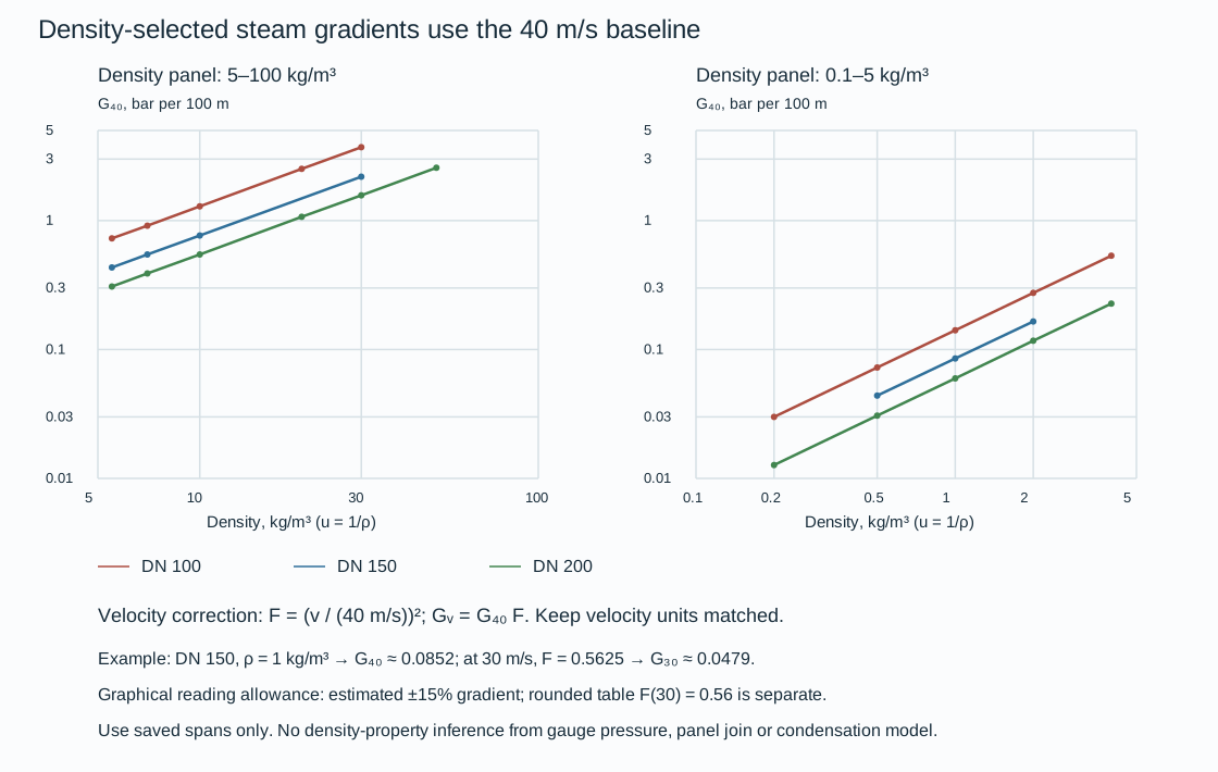
*Figure 1.6. Selected density curves for DN 100, 150 and 200 at 40 m/s. Interpolation joins log(density) and log(gradient) within a saved curve span only. The two panels are not joined. [State curves, recovered samples, correction table and worked inputs](assets/C01/c01-steam-hydraulics.json) preserve the numerical conditions. The [drawing implementation](assets/C01/c01-packet02.draw.py) regenerates the native figures from saved data.*
A steam line does not become constant-density merely because a chart supplies one point. Accurate gas and vapor pressure-loss evaluation needs a method that follows density, pressure, temperature and phase through the path. A bounded approximate procedure can use density and mean velocity at either inlet or outlet for a loss below 10% of upstream **absolute** pressure. A loss of 10–40% uses averages of inlet and outlet values.
Those conventions describe an approximate method where an accurate result is not required. They do not validate a large loss, a long cooling route, a choked condition or a two-phase calculation. At a larger or otherwise consequential change, use the appropriate compressible-flow/property calculation rather than extend this chart.
Condensate formation changes the physical problem. The dry-vapor curves cannot represent a flooded low point or flashing return. [Steam and condensate behavior](#chapter-c12) and [thermal treatment](#chapter-c14) provide the phase and heat-loss context. This hydraulic method supplies no distribution, consumer, trap or control arrangement.
## Short gas lines can make acceleration part of the pressure loss
A short gas passage can change velocity enough that kinetic-energy change matters alongside wall friction. A liquid constant-density formula does not represent that mechanism. Conversely, a pressure-loss correlation suitable for a long pipeline does not automatically describe a short entrance-to-outlet passage. Before transferring numerical results, preserve the pressure stations, inside bore, length, mass flux and compressible-flow model.
A bounded dimensionless chart uses the abscissa
$$
x=\frac{G}{P_1}\sqrt{\frac{P_1V_1}{g}},
$$
The chart uses the ordinate $P_2/P_1$ and a family parameter labeled $fL/D$. Here $G$ is **mass flux**, distinct from total mass rate, and $V_1$ is **specific volume**, distinct from velocity. The original customary-unit definitions give:
- $G$ in lb/(s·ft²);
- Pressures in lb/ft²;
- $V_1$ in ft³/lb;
- Pipe length $L$ and actual inside diameter $D$ in feet;
- $g=32.2$.
The friction factor is not identified as Darcy or Fanning. The numerical gravity entry alone does not establish the legacy mass/force conversion convention.
The pressure stations introduce a further limitation. The diagram puts $P_1$ in the upstream reservoir, $P_0$ at the pipe entrance and $P_2$ at the outlet. The textual definitions call $P_1$ inlet pressure and do not define $P_0$. Do not silently set $P_0=P_1$ or move an entrance loss into another station. Pressure ratios and property evaluations need compatible absolute pressures. Converting a gauge indication to absolute pressure does not resolve this station ambiguity.

*Figure 1.7. Selected recovered solid curves labeled isothermal, $k=1.0$, for printed $fL/D$ values 0, 2, 4, 10 and 20. A separately recovered dotted curve is labeled $k=1.4$ at $fL/D=0$. The dotted label alone does not establish an adiabatic heat-transfer model.*
*Curves are recovered only over saved spans, chiefly outlet ratios 0.8–0.95. Straight joins interpolate along a saved curve. No interpolation between family parameters or extrapolation toward a critical endpoint is supplied. Estimated graphical reading allowances are ±0.015 in pressure ratio and ±0.005 in $x$.*
The printed critical-outlet relations can be compared on this same **dimensionless** basis:
$$
\frac{P_{cr}}{P_1}=x\quad(k=1.0),\qquad
\frac{P_{cr}}{P_1}=\sqrt{\frac{2}{k(k+1)}}x\quad(k=1.4).
$$
For $k=1.4$ the multiplier is approximately 0.7715. With an explicitly assumed $x=0.15$, the formula ratios are 0.150 and approximately 0.116. These lines mark the chart's critical-ratio relation. They do not supply a generic valve choked-flow rule or a relieving-capacity result. The sparse recovered family traces are not extended to intersect the critical lines.
At the same assumed $x=0.15$, linear joining of the recovered solid $fL/D=10$ samples gives $P_2/P_1\approx0.854$. The $fL/D=4$ samples give approximately 0.931. Their estimated ratio ranges are about 0.839–0.869 and 0.916–0.946, before accounting for uncertainty in the selected abscissa. This comparison shows how the chart changes outlet ratio at a held dimensionless input and a different labeled friction-length parameter. It does not convert a project length or mass rate into those parameters.
The [saved chart data, literal station definitions and formula evaluations](assets/C01/c01-short-gas.json) distinguish recovered points from equations and teaching assumptions. The [drawing implementation](assets/C01/c01-short-gas.draw.py) reproduces the native chart.
For a dimensional project evaluation, stop at the missing model inputs. Establish:
- The pressure-station definitions;
- Compatible absolute pressure and specific-volume basis;
- Mass/force/gravity convention;
- The friction-factor convention used by the adopted compressible method.
Mass flux then belongs to actual flow area, not nominal pipe size. Selecting a convenient factor or assuming reservoir pressure equals pipe-entry pressure would manufacture a normalization the chart does not establish. This bounded dimensionless method explains the pressure-ratio comparison while preserving that limit. It provides no long-pipeline, valve or relief-sizing acceptance.
## A condition is not the complete state
Evaluate conditions with the actual connected configuration, temporary restrictions and active contacts. Normal operation does not represent installation, testing or maintenance.
A line in service may be hot, filled and free to move at a selected support. During construction it may be empty, incompletely insulated and temporarily restrained. During a test it may contain a denser liquid, be isolated by temporary blinds and have a spring blocked. During maintenance a heavy valve or spool may be removed, leaving a different connected assembly. The same line identity can persist through all of these states. The relevant weight, pressure boundary and load paths can change.
Pressure and temperature need the same discipline. Operating conditions describe the intended process envelope. Upset conditions address identified departures. Design conditions provide the adopted basis for selecting and evaluating the pressure boundary. Component ratings and allowable quantities belong to the component and governing evaluation basis. They are not interchangeable with a measured operating value.
Test conditions describe the specified verification state. A successful observation at normal operating pressure does not establish the design envelope. A successful test of one isolated boundary does not establish every later operating configuration.
Retain the combinations and configurations that produce the pressure. In a system containing a pump, a changed inlet pressure contributes to its discharge condition. A normal flow configuration and a blocked path can impose different demands. A pressure-generating machine, an isolated liquid segment and a heated vessel need different explanations of how pressure can rise. [Pressure design, relief and depressurization](#chapter-c08) develops the protective basis and its applicable criteria. The first task is to make the relevant system and state visible, so that protection is evaluated for the right problem.
Regeneration, steam-out and decoking may impose temperatures and movements absent from normal production. Retain their participating equipment, temporary connections and affected envelope.
A practical state inventory can begin as a concise working table. Populate it with the actual activities and conditions relevant to the system. Do not assume every row below is mandatory for every installation.
*Table 1.1. Relevant system states and evaluation consequences.*
| State or activity | What can change | Consequence to carry into evaluation |
|---|---|---|
| Normal operation | Flow, composition, level, pressure and temperature within the operating envelope | Process performance, containment and equipment interfaces |
| Startup or shutdown | Participating equipment, flow paths, filling/draining and relative temperatures | Temporary pressure, phase, movement and operating arrangements |
| Defined special service | Regeneration, steam-out or maintenance-related connections and temperatures | A different thermal or process envelope from normal production |
| Installation | Connected equipment, empty weight, insulation and temporary restrictions | Construction stability, fit-up and intended final geometry |
| Pressure testing | Fluid density, boundary, blinds and support/restraint configuration | Head, weight and reactions in the actual test state |
| Maintenance or repair | Isolation, contents, removed items and temporary support | Safe intervention and support of the remaining assembly |
| Modification or changed service | Components, fluid, pressure/temperature, routing or restraints | Reopening the assumptions and neighboring interfaces affected by change |
## The model represents a selected system state
A mechanical model can retain a weight support after the pipe has lifted clear of it. That model contains a load path absent in that operating state. A pressure test carried out with temporary boundaries does not represent the final flow path until restoration is complete. A drawing showing a clear maintenance space does not ensure that later field-run piping leaves the space clear. These are differences between representation and installed reality. A more precise calculation alone cannot repair them.
The model must represent contents, temperature, connected equipment, imposed movements and active restraints or contacts under the applicable evaluation criteria.
More than one load case may be needed to evaluate a state. Different physical evaluations may examine the same state for different reasons. A hydraulic check, a pipe-stress calculation and a structural reaction check are related evidence. One passing result does not automatically satisfy the others.
Compare installed geometry, settings and movement freedoms with the evaluated configuration. A change in fluid condition, movement or contact reopens the affected model inputs.
## Keep what is known distinct from what is chosen
The [test-boundary pressure example](#c18-pressure-method) separates assumed component limits from the elevation calculation. Its 12 m height difference and liquid density determine the pressure difference. The assumed top-point minimum and low-point maximum then constrain the permissible gauge setting.
Whether that pressure is acceptable requires the applicable boundary, material, component and evaluation criteria. Changing the height or density changes the result. Changing an allowable changes the decision about the result. Neither change should be hidden by calling both quantities the design basis.
Criteria also need an application. Plant process piping, pipeline systems, boiler-related piping and offshore interfaces can have different governing boundaries. Establish the applicable codes, editions, jurisdictional requirements, project specifications and equipment limits for the actual undertaking. Historical references to ASME or API explain an engineering route where relevant. They do not establish present compliance. [Buried piping, pipelines and offshore interfaces](#chapter-c11) preserves the distinct system boundaries, and the specialist chapters carry the local criteria that influence their choices.
An unconfirmed vendor removal dimension prevents fixing the withdrawal envelope. A missing allowable prevents an adequacy conclusion. Preliminary arrangements can proceed only within the consequences of those unresolved inputs.
## Compare solutions through the interfaces they change
The shortest or simplest-looking route is not necessarily the best system. A short hot pump suction line may reduce flow resistance while remaining mechanically stiff. Adding length and elbows can increase flexibility but also increase pressure loss. If a larger diameter is proposed to reduce that loss, its changed mechanical behavior has to be reevaluated. Hydraulic and mechanical choices interact. The first accepted calculation is not permanently fixed.
The same reasoning applies to access and construction. A compact equipment connection can use fewer fittings yet leave no practical spool for erection adjustment or component removal. An arrangement with deliberate break-out space may cost more initially but reduce recurring maintenance work. A dike or structure can perform its immediate function while constraining access, drainage or a piping route. Compare the complete arrangement across the states and tasks that give these features their purpose. [Plant arrangement, access and constructibility](#chapter-c04) develops the spatial method, and [equipment and storage interfaces](#chapter-c06) develops the particular physical requirements.
## Compare diameter by annual capital and flow-energy cost
A pump or compressor can supply the energy needed to overcome flowing resistance. In that case, increasing the bore can exchange higher installed piping cost for lower machinery and energy cost. Compare feasible pipe sizes on a common annual basis. A line driven only by available pressure has a different selection problem. It must pass the duty within the available pressure and applicable limits. An economic minimum cannot create missing suction head, remove cavitation or make an incompatible material acceptable.
A customary-unit liquid correlation expresses annual comparable cost per foot as
$$
C_{\ell}=\frac{FD}{r}
+7.85\times10^{-6}\frac{KSQ^3f_D}{D^5},\qquad
F=(1+X)L_{II},\qquad
K=\frac{Yk}{r}+8760\,c_h\,t.
$$
In this equation, $C_{\ell}$ is chosen-currency dollars per foot per year. The variable $D$ is **inside diameter in inches**, and $Q$ is US gallons per minute. The variable $S$ is liquid specific gravity relative to water at 60°F, and $f_D$ is a dimensionless Darcy friction factor. $F$ is total installed pipe cost per diameter-inch per foot, including the relevant painting, tracing and insulation. The variable $L_{II}$ is material plus direct field cost on that same basis. The variable $X$ is the indirect-field-cost fraction.
The symbol $L_{II}$ is a cost coefficient, not pipe length. $r$ is a simple before-tax payout period in years.
The variable $k$ is purchased machinery cost per hydraulic horsepower, and $Y$ is its installation multiplier. The variable $K$ is comparable annual machinery and operating cost per hydraulic horsepower.
The load fraction $t$ is operating hours divided by 8760, with 80% entered as 0.80.
The electrical energy rate $c_e$ is in dollars per kWh, and combined pump/driver efficiency $\eta$ is a fraction. With those units, $c_h=0.7457c_e/\eta$ in dollars per hydraulic-horsepower-hour. An 80% efficiency is 0.80, not 80.
The correlation's numerical coefficient contains its customary units. To rounding, the coefficient is consistent with Darcy pressure loss and hydraulic power $Q\Delta p/1715$ in horsepower for gpm and psi. It also uses water density near 62.4 lb/ft³.
Do not transplant that coefficient into an SI calculation. Before inserting a Fanning factor, apply its fourfold conversion. When viscosity, regime or duty changes, use the appropriate friction and machinery model.
If $f_D$, costs and efficiency are held constant while considering continuous diameter, differentiating this objective gives
$$
D_* = \left(
5\times7.85\times10^{-6}\frac{KSQ^3f_Dr}{F}
\right)^{1/6}.
$$
This is a continuous teaching optimum, not a purchasable nominal size. Its dependence on the cost ratio is weak. Doubling $F$ alone multiplies $D_*$ by $2^{-1/6}\approx0.891$. Doubling $K$ alone multiplies it by $2^{1/6}\approx1.122$.
The relation is conditional on the constant-factor approximation. A revised bore can change Reynolds number and roughness ratio, requiring a new factor and cost comparison.
Equal length multiplying both diameter-dependent terms does not move this simplified optimum. Diameter-independent losses must still enter the complete hydraulic balance, even though they do not change this derivative.
Use actual installed and machinery costs, currency, tariff, demand charges, load fraction and efficiency. The dated correction-chart and machinery-cost inputs retained in the structured companion are not current estimates; its gas temperature convention needs confirmation before numerical use.
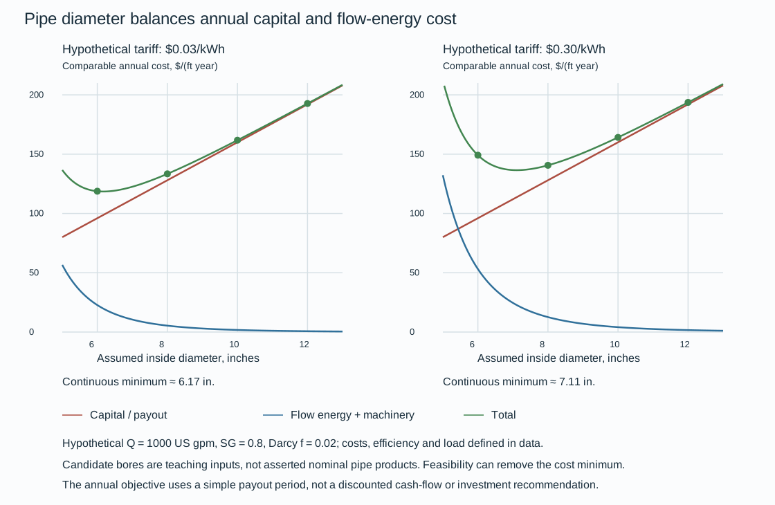
*Figure 1.8. Hypothetical cost comparison at 1000 US gpm, $S=0.8$, Darcy $f_D=0.02$, $F=80$ dollars per diameter-inch per foot and a five-year payout. Machinery purchase cost is assumed 2000 dollars per hydraulic horsepower, installation multiplier 3, combined efficiency 0.75 and load fraction 0.80. The left and right energy rates are 0.03 and 0.30 dollars/kWh.*
*The candidate inside diameters 6, 8, 10 and 12 inches are teaching inputs. No particular nominal pipe product is asserted. The plotted annual objective is not discounted cash-flow analysis.*
At the lower energy rate, the annual machinery/energy coefficient is about 1409 dollars per hydraulic horsepower per year. The 6- and 8-inch teaching bores give approximately 118.8 and 133.4 dollars per foot per year. Among the four candidates, 6 inches has the lower objective.
At the higher energy rate, $K$ rises to about 3290. Those candidates give approximately 149.1 and 140.6 dollars per foot per year, favoring 8 inches.
Continuous minima are approximately 6.17 and 7.11 inches. These results explain a cost sensitivity, not a recommendation for a real line. A pressure-loss constraint can eliminate the smaller candidate and leave a different feasible minimum.
### Compare the complete valve assembly and its velocity reference
A smaller valve may save capital while adding flow-energy demand, reducer cost and installation space. For an installed assembly comparison:
- Include the valve, flanges and reducers.
- Use losses for the actual fully open flow path and the same physical coefficient reference.
An adopted dimensionless coefficient $K_A$ referenced to velocity in the valve bore gives the customary-unit liquid estimate
$$
\Delta p_{\mathrm{psi}}=0.0011\frac{SQ^2K_A}{d^4},\qquad
P_H=\frac{Q\Delta p_{\mathrm{psi}}}{1715},
$$
In these equations, $d$ is actual valve inside diameter in inches and $Q$ is US gpm. The variable $S$ is liquid specific gravity and $P_H$ is hydraulic horsepower. The approximate expanded power expression is $6.4\times10^{-7}SQ^3K_A/d^4$. Using $Q\Delta p/1715$ keeps the pressure and power calculation internally consistent with the displayed rounded coefficient.
A coefficient based on upstream pipe velocity cannot be added directly to one based on valve-bore velocity. Convert both to one velocity reference or use validated whole-assembly pressure-loss data. Viscosity and other departures from this bounded liquid relation require the appropriate component method.
With installed assembly cost $A$, the annual comparable cost is
$$
C_A=\frac{A}{r}
+\frac{0.7457}{\eta}P_H\left[b+8760c_e t\right].
$$
In this equation, $C_A$ is dollars/year and $b$ is demand charge in dollars per kW-year. The variable $c_e$ is energy rate in dollars/kWh. Both efficiency $\eta$ and load $t$ are **fractions**. When demand cost is already included in the adopted tariff, set $b=0$. Charging it again would double-count it.
The expression assumes the incremental machinery capital treatment embodied in the chosen comparison. Include a machinery or electrical upgrade when the added loss actually requires it.
For a bounded gas assembly relation, the corresponding customary-unit expressions are
$$
\Delta p_{\mathrm{psi}}=
\frac{2720K_A}{d^4\rho}
\left(\frac{M}{100000}\right)^2,
\qquad P_H=\frac{M\Delta p_{\mathrm{psi}}}{13750\rho},
$$
In these expressions, $M$ is in **lb/h**, $\rho$ in lb/ft³ and $d$ in inches. Before entering a mass rate stated in thousand pounds per hour, multiply it by 1000. These local gas loss/power correlations do not replace a compressible-flow calculation when state changes are consequential. The expanded coefficient 19782 is rounded. No gas optimum is evaluated here without adopted state and assembly-loss data.

*Figure 1.9. Hypothetical fully open assemblies with actual bore 6 inches and installed cost 6000 dollars, $K_A=0.8$, or bore 8 inches and cost 10,000 dollars, $K_A=0.2$. Both coefficients are assumed whole-assembly values referenced to valve-bore velocity. Other inputs are $S=0.8$, five-year payout, efficiency 0.75, load 0.80, energy rate 0.10 dollars/kWh and demand charge 50 dollars/kW-year. These are teaching assumptions, not manufacturer data or product prices. [Equation definitions, historical conditions, hypothetical inputs and calculated results](assets/C01/c01-diameter-economics.json) keep the cost and loss bases recoverable.*
At 1000 US gpm, the assumed assemblies lose about 0.543 and 0.0430 psi, yielding annual totals about 1436 and 2019 dollars respectively. At 2000 US gpm, their losses rise to about 2.17 and 0.172 psi and annual totals to about 3092 and 2150 dollars. The larger assembly becomes the lower-cost candidate. For fixed bore, coefficient and SG, doubling flow quadruples pressure loss and multiplies hydraulic power by eight. A changed operating fraction or efficiency also changes annual cost. Preserve those inputs with the state being compared.
Coefficient selection must precede a real comparison. The larger-size branch of a gate-valve relation is stated both as a constant 0.14 and as $0.14d$. This does not establish a unique coefficient for $d\ge14$ inches. Under its stated velocity and acceleration units, the enlargement expression $h=((V_1-V_2)/(2g))^2$ gives time squared, rather than head in feet.
Neither ambiguity is used in the numerical examples. No corrected formula is silently substituted. Before evaluating those branches, obtain a validated loss relation or assembly data.
A piecewise enlarger relation with strict diameter ratios below and above 0.8 also leaves equality undefined. Its diameter/velocity reference must be established before combining coefficients.
The lowest annual objective is useful only among alternatives meeting the adopted hydraulic, NPSH, cavitation, pressure, erosion, phase, material and mechanical constraints. Reducers can affect stress and drainability. Larger hardware can affect support load, access and removal space. Evaluate discrete available products and the actual configuration, including credible changes in flow and duty. [Pump suction conditions](#chapter-c05), [pressure design](#chapter-c08), [mechanical evaluation](#chapter-c09) and [access and constructibility](#chapter-c04) can each remove a mathematically attractive candidate from the feasible set.
## Carry the decision into installation, operation and change
Unconfirmed equipment envelopes may support plot alternatives without supporting final spool fabrication. Assumed liquid levels may support hydraulic sensitivity work without becoming operating data. Preserve the dimensions, component identities, settings and conditions on which the selected configuration depends.
[Engineering records, human factors and lifecycle decisions](#chapter-c21) develops the durable identities, revisions and work-system verification that connect these outputs.
A modification reopens the affected relationships. A replacement valve can change weight and removal space. A new temperature or fluid can change movement, density or material suitability. An added restraint intended to reduce vibration can oppose thermal movement. Changed operation can activate a previously unused flow path.
Reevaluate the neighboring components, states and calculations affected by a modification, retaining valid unrelated work.
[Operating integrity and maintenance](#chapter-c19) and [repair and modification](#chapter-c20) develop those interventions.
# Chapter 2 — Materials, piping classes and procurement requirements
## Choose the material for the service it will actually see
Select material, product form and joining system for coincident pressure, metal temperature, fluid composition, contaminants, velocity and external exposure. Include startup, shutdown, cleaning, steaming and depressurization from [the engineering basis](#chapter-c01). Dry operating gas can become wet and corrosive during an outage; a high-temperature material can face brittle-fracture risk when pressurized cold.
Compare operating experience only where fluid, contaminants, velocity, temperatures, manufacturing condition and shutdown practice are relevant. General thinning, weld cracking and rapid elbow thinning imply different responses. The selection must be fabricable, inspectable and replaceable at the installation; the piping class and purchase description must carry its delivery condition, damage-management approach and pressure-temperature basis.
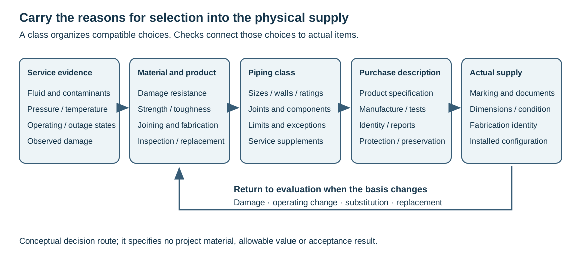
*Figure 2.1. The decision route returns to evaluation when damage, operating conditions or the proposed supply changes.*
## Metallic materials solve different problems
Carbon steel is a common starting point because it combines useful strength, familiar fabrication and broad availability. It is not a neutral choice for every fluid. General corrosion, erosion-corrosion, wet hydrogen-sulfide damage, hydrogen attack and environmental cracking have different causes and require different responses. A predicted general loss of wall may be addressed by allowance and inspection. Cracking can destroy containment without consuming the assumed allowance uniformly. Increasing thickness cannot, by itself, demonstrate resistance to that mechanism.
Strength and toughness are also different properties. A material may have adequate allowable stress for pressure containment and inadequate resistance to brittle fracture at a low metal temperature. Toughness depends on material, product form, heat treatment, thickness and manufacturing history. A low-temperature grade, impact-test requirement or specified heat treatment therefore belongs in the purchase description. It is not enough to change the temperature on a line list while retaining a component selection that was made for warmer conditions.
At elevated temperature the choice may turn on strength, oxidation, microstructural change and the particular fluid environment. Chromium-molybdenum steels provide advantages in high-temperature strength and, under appropriate conditions, resistance to hydrogen attack. Those advantages bring welding and heat-treatment obligations. Carbon-molybdenum steel shows why alloy content alone is insufficient. Improved high-temperature strength does not establish improved resistance to hydrogen attack. The material must address the mechanism that governs the service.
Stainless steel is a family of materials. It is not a single remedy for corrosion. Austenitic grades such as 304/304L and 316/316L differ in composition and resistance to particular environments. Chromium provides the basis for corrosion resistance, but chlorides, deposits, temperature, stress and external wet insulation can create a cracking problem.
A line can acquire harmful chloride contamination from test water or from conditions during shutdown. Sulfur-derived acids formed when sulfide deposits meet moisture and oxygen during an outage present another distinct concern, particularly for sensitized material. Normal operating compatibility does not settle these intervention states.
Low-carbon and stabilized austenitic grades address sensitization in different ways. Neither designation removes every consequence of prolonged thermal exposure. Duplex stainless steels combine ferritic and austenitic structures and offer useful strength and corrosion resistance. Fabrication and phase stability must also be part of the selection.
Ferritic and martensitic stainless steels have their own weldability and embrittlement considerations. Where an adopted class prohibits a family because of these concerns, that prohibition is part of the selection basis. A different stainless grade requires a new evaluation.
Nickel alloys may suit chemical environments for which common stainless steels are unsuitable. They cost more and have their own fabrication precautions. Titanium can provide valuable chemical resistance but demands particularly clean welding conditions and careful consideration of field repair. An alloy with excellent laboratory resistance may be a poor installation choice when suitable fabrication and replacement capability cannot be maintained.
Product form matters beside composition. A cast valve body and wrought pipe of broadly similar chemistry do not have identical manufacturing histories or toughness characteristics. Grey cast iron, ductile iron and cast steel differ substantially in brittle behavior. Likewise, seamless, electric-resistance-welded and electric-fusion-welded pipe are different products.
A longitudinal seam introduces manufacturing and examination requirements that a seamless product does not have in the same form. Whether a welded product is acceptable depends on the service, governing specification, manufacturing route, examinations and applicable design factors. A historical preference for seamless process pipe is not a universal rejection of qualified welded pipe.
The comparison below guides selection. It is not a table of permitted services or temperature limits. It states the reason to examine a family and the condition that can reverse that choice.
*Table 2.1. Material-family selection comparisons.*
| Material or construction | Reason to consider it | What can reverse the choice | Consequence for the installation |
| --- | --- | --- | --- |
| Carbon steel | Familiar fabrication, availability and useful strength | Unacceptable corrosion, cracking, low-temperature toughness or high-temperature degradation | Allowance and inspection must address the actual damage; grade, toughness and fabrication conditions remain explicit |
| Chromium-molybdenum steel | High-temperature strength and resistance to specified hydrogen environments | Unsuitable alloy level, embrittlement or inability to control fabrication | Preheat, heat treatment, welding and examination form part of the material choice |
| Austenitic stainless steel | Resistance to many environments that attack carbon steel | Chloride cracking, sensitization or harmful outage contamination | Test water, insulation, marking materials and shutdown protection affect integrity |
| Duplex stainless steel | Useful combination of strength and corrosion resistance | Service or fabrication conditions that impair the required structure/properties | Product qualification and controlled joining must accompany selection |
| Nickel alloy or titanium | Particular chemical resistance beyond common steels | Cost, availability, fabrication or repair difficulty; incompatible chemical conditions | Plan skilled fabrication, inspection and replacement with the initial selection |
| Thermoplastic | Chemical resistance, low mass and joint systems suited to the service | Temperature/duration-dependent properties, vacuum, fire, mechanical damage or joint restrictions | Use the qualified pressure-temperature/joint system and material-specific handling/support |
| FRP/RTR | Resin-dependent chemical resistance with fiber reinforcement | Wrong resin/liner, unsuitable joints, cure or loading | Treat pipe, fittings, adhesives, laminate and procedures as a compatible system |
| Lined steel | Structural steel with an internal chemical barrier | Liner damage, permeation, vacuum or discontinuity at joints | Preserve the barrier through fabrication, transport, assembly and inspection |
## Separate pressure wall, damage allowance and delivered thickness
The wall selected for pipe serves several purposes. Pressure design establishes a required thickness for the applicable pressure-temperature condition and material/product factors. Threading or grooving can remove wall. Corrosion and erosion can remove further wall during service. Manufacturing permits a specified variation about nominal thickness. The order in which these provisions are applied matters.
For straight metallic pipe, a useful relationship for thickness accounting is:
$$t_m=t_p+c_m+c_d,$$
In this equation, $t_m$ is the required minimum wall and $t_p$ is the pressure design thickness. The mechanical allowance $c_m$ covers features such as threads or grooves. The corrosion/erosion allowance is $c_d$. All four quantities use the same length unit.
The associated pressure-wall procedure is taught in its historical ASME B31.3 (1984) context; application uses the governing edition and product provisions. This relationship explains the components of the wall requirement. The governing pressure method, material factors and any minimum structural wall remain part of the adopted design basis. [Pressure design](#chapter-c08) develops the pressure calculation and the distinction between process-piping and pipeline methods.
If the product specification permits a fractional negative wall tolerance $u$, a nominal thickness $t_n$ must satisfy
$$t_n(1-u)\geq t_m,\qquad t_n\geq\frac{t_m}{1-u}.$$
Here $u$ is dimensionless. A 12.5% negative tolerance means $u=0.125$ and leaves $0.875t_n$ at the lower tolerance boundary. This is the historical seamless-pipe allowance used in the worked method. It is not a tolerance assigned to every pipe product. For wall selection:
- Apply the actual specification and manufacturing conditions.
- Then select an available nominal wall that satisfies the result.
Nominal wall, minimum required wall and measured remaining wall are distinct quantities.
The result says nothing by itself about external pressure, flexibility, local attachments, branch reinforcement or component ratings.
### A design floor and an inspection limit answer different questions
An adopted class can impose a minimum schedule even when a calculated pressure wall is smaller. That floor may preserve robustness, connection geometry or the construction basis. A successful pressure calculation does not delete it. Conversely, choosing the listed minimum schedule does not establish adequacy for loads omitted from the calculation.
A historical carbon-steel class-design provision illustrates the distinction. Its pressure-only procedure uses minimum design-wall values of 2.54 mm for NPS 3/4–3, 3.05 mm for NPS 4–6 and 3.30 mm for NPS 8–24. Those values apply only within the stated method. Temperature must be no greater than 260°C.
Pressure must be no greater than 2,400 kPa for NPS 14 and below, or 1,380 kPa for NPS 16–24. The provision states pressure in kPa without locally identifying gauge or absolute reference. Its adopted pressure reference and code basis must be established before applying those pressure comparisons. Outside that scope, and where the full load analysis is performed, calculated wall must address the relevant loads.
These are conditions of a particular design procedure, not universal carbon-steel wall limits.
Within that procedure, select the schedule from the applicable design floor plus the class corrosion allowance, with product tolerance, class minimum schedule and other required evaluations still applied. Do not substitute its definitions into another wall procedure.
The procedure explicitly excludes using those design-wall values as arbitrary inspection retirement limits. A new-design floor, an allowance for future loss and a minimum acceptable remaining wall have different purposes. Condition assessment needs the actual geometry, damage and service state, the applicable calculation or assessment method, and the inspection basis. A pipe does not become fit for further service merely because its measured wall exceeds a number copied from a new-design table. [Operating integrity](#chapter-c19) develops that assessment; [pressure design](#chapter-c08) and [load analysis](#chapter-c09) supply the relevant calculation interfaces. [Structured design-floor method](assets/C02/c02-design-floor.json) retains the scoped table and teaching inputs.
Base corrosion allowance on the expected damage over the intended period, including changes with temperature, contaminants, wetting and operation. Localized attack, erosion at fittings, cracking and external corrosion require separate evaluation.
The alternatives are added wall, a more resistant material, a lining, control of the corrosive environment, and inspection or replacement planned around the damage. They can be combined. Added wall is attractive when loss is sufficiently predictable and available thickness remains practicable. It becomes less convincing when the required allowance is large, the mechanism is localized, or the component cannot accommodate it.
An alloy or lining can reduce a particular damage mechanism but introduce joining, inspection or repair obligations. A suitable choice accounts for those consequences. Corrosion resistance is not a single ranking.
## Read sizes, schedules and ratings as different information
Nominal pipe size identifies a standardized size family. It does not state the measured outside diameter in every size. Wall schedule identifies a dimensional series, not a pressure rating independent of material and temperature. For a given outside diameter, increasing wall reduces the internal bore and increases mass. That changes flow resistance, support loads, fit-up and the transition into fittings as well as pressure capability.
Pressure class on a flange or valve is another designation. Class 150 does not mean that the component has a universal allowable pressure of 150 psi. Pressure-temperature ratings depend on the applicable component standard, material group and temperature. Pipe may be evaluated by its calculated wall while a valve or flange is evaluated by a standard rating. The system must satisfy both routes. A component’s material temperature limit, gasket limit or class note can govern before the pipe wall does.
Fittings supplied to match pipe wall require a compatible bore and end preparation. A heavier fitting may be commercially convenient, but a mismatch can require a specified transition without reducing either part below its required minimum wall. Very thin pipe can save material on a long straight run and become uneconomic in a short, fitting-rich arrangement that requires special fittings or taper boring. Standard walls can simplify availability and subsequent replacement. The economic comparison includes fittings, machining, fabrication and maintenance, not just kilograms of pipe.
### Carry wall changes into hydraulics, loads and connections
At fixed outside diameter, a thicker wall reduces bore and fluid inventory, increases pipe mass and changes bending stiffness. Recheck [flow resistance](#chapter-c01), liquid-filled test loads, [flexibility](#chapter-c09) and [supports](#chapter-c10) after a wall change. Greater stiffness can increase forces needed to impose a displacement. Use actual material properties and geometry, including lining, ovality, wall variation and end preparation. A nominal reference section does not establish delivered minimum wall or acceptable remaining wall.
Pipe and tube size labels use different conventions. A 1/2 in outside-diameter tube has a 12.7 mm OD; the selected nominal 1/2 in steel pipe data use 0.840 in OD. A pipe-thread-to-tube adapter needs both end descriptions. Insulation and lining quantities use each layer's actual geometry.
## A piping class binds compatible components
A piping class is a controlled set of component selections and conditions for a defined range of applications. It commonly identifies pipe materials and walls by size; fitting and branch arrangements; flange and valve classes; gasket and bolting; joining methods; corrosion allowance; and supplemental requirements such as impact testing, heat treatment or examination. Its service index helps locate a candidate class. The index does not replace reading the class limits and notes.
Class coverage must include coincident pressure-temperature states, cold/cleaning/upset conditions, required sizes and every component family.
A small-bore component or valve can have less available corrosion allowance than the larger pipe in the same nominal class. A class may state that exception explicitly. A common class heading therefore does not establish identical remaining-life provisions throughout the line.
Two wall-selection approaches are useful and must remain distinct. A class can supply walls calculated for its specified full flange pressure-temperature envelope, rounded to standard available schedules. Alternatively, an adopted procedure can permit a wall calculated for the actual line conditions. The latter can reduce weight or cost, but its narrower basis must be preserved in the line record and drawings. Raising the operating condition later cannot be justified merely because the flange has spare rating. The calculated pipe wall and every affected component must be reevaluated.
Joint restrictions belong beside material selection. Threaded or socket-welded connections can be excluded by a service, size or cyclic-loading criterion even when the base metal is otherwise suitable. A class may assign special branches or valve trims for the fluid, require a particular gasket, or exclude a valve type. A special item outside the class needs an explicit description of its material, ratings, ends and service requirements; “special” does not exempt the item from the system’s containment and mechanical obligations. [Components and pressure-retaining joints](#chapter-c03) and [Branches and small-bore connections](#chapter-c07) explain the hardware consequences.
A supplier alternative, field substitution or replacement can break compatibility at a flange, dissimilar-metal weld, gasket, valve trim or nonmetallic joint. Compare the proposed item with the original selection basis.
### Follow a candidate class into the actual item and work
Read the service index together with its identified detailed class, code/application boundary, revision, envelope, size-dependent product rows and attached notes. Similar class names, suffixes or pressure groups from another basis are not interchangeable.
One class method separates construction quality from flange pressure rating. Its construction classes combine component quality, inspection and fabrication provisions selected for severity of service. The piping class must be permitted for the required construction quality. A higher flange rating does not establish that quality, and increasing quality indiscriminately can add cost without supplying a needed function. The adopted requirement and its purpose must remain explicit. The organization's numbered quality levels are not universal grades.
A detailed family can illustrate the selection. Three sour-service candidates share Class 150 flanges and a material-group rating basis. One warm candidate has a 1.5 mm minimum corrosion allowance. Another has 3.0 mm.
A cold candidate also has 3.0 mm. It changes the pipe, fittings and flange products to A333 Grade 6, A420 WPL6 and A350 LF2. It also extends its declared lower temperature from −29°C to −45°C. The changed allowance and changed product condition answer different questions.
Increasing an allowance does not create low-temperature toughness, and retaining the same flange class does not make the component descriptions equivalent.
Their rows continue the decision into pipe wall, end preparation, bolting, gasket, valve description and local service notes. An adopted sour-product certification, particular bolting grades or a verified trim condition is not supplied by matching only the pipe's nominal composition. Dual certification must establish the represented product's required bases. Two standard names beside a similar grade do not prove that the delivered item meets both. The purchase and receiving route later in this chapter preserves those distinctions.
A component note can govern inside the apparent class envelope. In the selected warm candidate, the class range reaches 204°C, while a note attached to its ball valves limits those selected items to 100°C. That selected valve cannot cover a 140°C condition. Its local limit does not define all ball valves; pressure, cold state, material suitability and function still require verification.
*Table 2.2. Read the candidate through its dependent engineering decisions.*
| Selection step | Evidence to use | Consequence to preserve |
| --- | --- | --- |
| Service and application | Fluid/state, code boundary, coincident conditions and actual class identity | Process and pipeline classes can use different product and design bases |
| Class envelope and wall | Material group, stated pressure/temperature limits, allowance, minimum schedule and applicable calculation | Component rating or a convenient schedule does not expand the permitted class conditions |
| Local item and segment | Size range, material/end/trim description and attached notes | A valve temperature cap, cold product, lining or local fluid segment can govern separately |
| Manufacturing and fabrication | Product category, certification, joining, PWHT and its qualified exemptions | A substitution or exemption must reach the fabricator's actual instructions |
| Examination and restoration | Selected extent/method, service state, actual installed configuration and evidence | A percentage, drawing revision or class header alone does not establish accepted work |
Pipeline examples make the application boundary particularly visible. Where a detailed class explicitly limits pressure to the lower rating from its stated flange/component bases, both must be evaluated under their applicable conditions. That is an express selection rule within the class; it is not permission to combine unrelated rating tables. Its wall schedules can also depend on design factors that the procedure requires the designer to verify.
If those factors do not apply to the actual line, the wall requires recalculation. The printed schedule depends on its premise. Product categories, manufacturing routes and pigging requirements still travel with that selection. [Pipeline and offshore systems](#chapter-c11) develops the system application.
The item roster matters as much as a common wall-data strip. A cold stainless candidate can show larger-size columns in the strip while listing pipe, flanges and valves only through NPS 12. Those columns do not add the missing products to the class. Likewise, a sanitary drain class with ABS pipe, compatible socket fittings and solvent cement explicitly excludes use where steam cleaning is required.
The class may suit the ordinary fluid but not the intended intervention state. A copied metallic schedule strip or an N/A pressure field cannot establish an ABS system's rating. [Cleaning and readiness](#chapter-c18) carries the selected intervention basis into work.
The index and detailed class can also disagree. In a matched family, a summary gives code-based PWHT while the detailed sheet states all welds with a particular approved-procedure exemption. In other matched entries, the summary and detail give different temperature maxima. Preserve the actual versions, entries and note conditions and reconcile the applicable basis before releasing the selection.
Taking the larger temperature or the more demanding heat-treatment phrase does not resolve their different meanings. The index's direction to use the detailed class is a reason to examine it. Agreement must not be assumed where the records differ.
The work must use the resolved selection. Some service states distinguish liquid and gas examination extents; some PWHT exemptions require their use to be identified on the fabricator's drawings. A material change in a local process segment, a differently rated soft good or a revised cleaning method can reopen the class relationship without changing the general fluid name. [Heat treatment and examination](#chapter-c16), [construction](#chapter-c17) and [engineering records](#chapter-c21) preserve those outputs and their verified installed state. [Structured class walkthrough](assets/C02/c02-class-walkthrough.json) records the hypothetical temperature comparison and the decisions it leaves open.
## Nonmetallic piping is a material and joint system
Thermoplastics change stiffness and strength with temperature and duration of loading. Their chemical resistance, low mass and smooth bore can make them attractive, but a room-temperature pressure marking does not establish capability at a warmer sustained condition. Pressure, temperature, fluid compatibility, joint type, vacuum and mechanical support must be evaluated together. The installation can also be exposed to sunlight, fire, impact and temperatures during cleaning that exceed its normal fluid condition.
HDPE is commonly joined by heat fusion, with transitions to metal or equipment made through qualified mechanical arrangements. The pipe material, dimensions, fusion procedure, equipment settings and operator qualification act together. Dissimilar wall thicknesses or materials require evaluation against the qualified procedure before they can be treated as an ordinary same-pipe fusion. General-purpose piping and piping supplied under a particular fire-protection approval can have different joining and acceptance restrictions. A procedure written for one is not automatically applicable to the other.
PVC, CPVC and ABS often use solvent-cemented joints. Surface preparation, compatible cement, assembly and cure establish the joint. A dry-looking joint is not evidence that it is ready for pressure. CPVC has a different temperature capability from PVC, but it still requires a compatible product and service basis.
PP, PVDF and PB provide further alternatives, commonly with fusion or other system-specific joints. Their advantages must be assessed against the actual chemical environment and pressure-temperature condition. The generic word “plastic” does not establish suitability.
A mechanical connection can be convenient for removal or transition while providing different axial restraint from a fused joint. Pressure thrust, thermal movement and support therefore remain part of the choice. Plastic flanges and adapters also respond differently to bolting from steel assemblies. Excessive local compression or poor alignment can damage the nonmetallic component. Support must distribute load without cutting or abrading the pipe and must account for thermal movement, valve masses and the temperature-dependent properties. [Support selection](#chapter-c10) develops these consequences, and [Fabrication and construction](#chapter-c17) carries them into installation.
FRP or RTR piping contains reinforcement, resin and often a corrosion-resistant internal layer. Resin selection answers the chemical exposure; reinforcement and laminate construction answer structural demands. A change in resin, liner, reinforcement or manufacturing method changes the product. Adhesive and butt-and-wrap joints likewise require compatible materials, preparation and cure. Pipe, fittings, flanges and adhesives from different manufacturers are not interchangeable under an aboveground RTR procedure that prohibits such mixing. That procedure’s scope excludes underground, mechanical-joint and fire-water systems; those variants need their own basis.
Cure is a physical part of joint formation. Temperature, time and the prescribed process affect whether the resin or adhesive achieves the intended condition. Handling or loading an uncured joint can defeat an otherwise sound selection. Chemical resistance may be supported by relevant field experience or laboratory testing, but the compared exposure must represent the intended service. A generic FRP pressure designation cannot identify the resin or prove chemical compatibility.
Concrete piping is a distinct alternative for suitable water, drainage and other applications. Structural form, reinforcement or a steel cylinder, joint construction, exposure and installation loading matter. It should not inherit thermoplastic joining or support assumptions merely because both are grouped as nonmetallic. [Buried systems](#chapter-c11) develops the interaction with bedding, soil and installation.
### Locate the joining interface and the axial load path

*Figure 2.2. Selected upper-wall sections locate fused or bonded interfaces, a reinforced overlay, and separate sealing and retaining features. These are mechanism comparisons, with [structured joint relationships](assets/C02/c02-nonmetallic-joint-paths.json).*
Butt fusion brings prepared, aligned and heated end faces together. The double bead accompanies the joining interface. Socket fusion heats the outside of a male end and the inside of a socket with their matching tools before assembly. Solvent cementing uses prepared surfaces and compatible cement instead of that heating operation. The similar overlap in panel B does not make those two formation processes interchangeable. Their material, preparation, assembly window, cooling or cure conditions remain with the qualified system.
An adhesive bell joint develops its bond over the prepared mating surfaces. A butt-and-wrap joint instead bridges prepared ends with resin-impregnated reinforcement. A selected construction may also require an inner-surface overlay. An external or internal overlay over another joint is a defined additional construction.
The selected construction must preserve access for bond preparation and examination, including any required inner barrier. An outer wrap cannot compensate for an omitted internal layer or unprepared interface. [Joining](#chapter-c16) and [construction](#chapter-c17) retain formation, cure and examination requirements.
A seal and an axial restraint answer different questions. An unrestrained O-ring can close a leakage path while permitting the ends to separate under axial thrust. The installation must supply its qualified thrust-resisting arrangement. A restrained O-ring joint adds a distinct mechanical load path, such as its specified threads, clamp, key or retaining ring.
Panel F represents that separation of duties, not a particular interchangeable coupling. The actual engagement, component compatibility and pressure-temperature basis require evaluation. A gasket's visible presence cannot establish the retaining feature's capacity.
Flange adapters and specialty transitions introduce further interfaces. The nonmetallic stub end or adapter joins its pipe through the qualified material process, while the backing flange and bolted seal connect it to another component. A metal transition retains its particular polymer retention, sealing arrangement and metal-end preparation. Each interface needs protection during welding, handling and assembly. The complete product rating requires verification. Neither the metal end nor the straight pipe's pressure calculation automatically rates the entire transition.
Before applying a restraint example, select the installation route. One adopted general-purpose HDPE route requires a fully pressure-rated and fully thrust-restrained mechanical coupling. Under the specified longitudinal-load criterion, the pipe must yield before the coupling separates. This route expressly rejects external restraint as a substitute.
Its fire-protection-approved route instead permits its flange-adapter/backing-ring connections and excludes mechanical couplings and external joint restraints. Those requirements cannot be replaced by the historical seal-only joint's separate thrust-block or burial arrangement. Keep the selected system, approval and load path together through procurement and installation.
### Calculate internal pressure from minimum wall and qualified factors
A thermoplastic pipe's internal-pressure evaluation uses its qualified material strength, minimum product wall and service conditions. It answers a different question from the external-pressure stability calculation below. A modulus used to model collapse is not a hydrostatic design stress, and a satisfactory internal-pressure result does not establish vacuum capability, acceptable support spacing or joint qualification.
For a selected historical thermoplastic method, define the standard dimension ratio as
$$SDR=\frac{D_o}{t_{min}}.$$
In this equation, $D_o$ is the pipe outside diameter and $t_{min}$ is its minimum wall thickness. Use the same length unit for both, making SDR dimensionless. A lower SDR describes a greater minimum wall relative to outside diameter. Nominal pipe size is not $D_o$, and nominal wall is not automatically $t_{min}$. Establish the product's actual dimension and tolerance basis; do not assign the historical steel-pipe negative tolerance to every thermoplastic product.
The method can then be written in equivalent forms:
$$P_T=\frac{2S_H}{SDR-1}F_TF_EF_J
=\frac{2S_Ht_{min}}{D_o-t_{min}}F_TF_EF_J.$$
In these equations, $P_T$ is the design-pressure quantity calculated by this method. $S_H$ is hydrostatic design stress for the selected material and qualification basis. $F_T$, $F_E$ and $F_J$ are dimensionless temperature, environment and joint factors. $P_T$ and $S_H$ use the same pressure unit; $D_o$ and $t_{min}$ use the same length unit. The equation illustrates the adopted method, not a universal rating for plastics or a current code permission. Establish the pressure reference for an application; the following examples retain the method's psi quantities without using them for an absolute-pressure or gas partial-pressure calculation.
Hydrostatic design basis and hydrostatic design stress have separate roles. In this historical route, the design stress is the hydrostatic design basis divided by two. For the pressure calculation, use the actual qualified stress and its material, temperature, duration and method basis. A tensile-strength value, a short burst result or an elastic modulus cannot replace it.
The stress reference and factor schedule belong together. A second temperature reduction on an already adjusted stress is appropriate only if the selected method requires it. Material designation conventions can help identify a specified product, but they are not a universal decoder of its allowable stress.
The factors also have separate purposes. The evaluation must account for external heating as well as fluid temperature, including solar heating of aboveground pipe. Temperature can reduce pressure capability, while exposure to hydrocarbons can introduce another reduction even where the base polymer remains chemically usable.
The selected joint has its own factor and eligibility. In the historical HDPE route, the environment factor is 0.5 for hydrocarbon exposure, including small quantities, and the joint factor is 1.0 for butt fusion. A PVC/CPVC route instead uses 0.4 for hydrocarbons, 1.0 for solvent-cemented joints and 0.5 for eligible threaded joints. Those are different material and joining bases.
The arithmetic cannot authorize a chemical exposure excluded by the material selection or a joint excluded by size, temperature, service or approval conditions.
A joint-factor entry is particularly easy to misuse. A separate PP/PB/PVDF method lists a 0.5 threaded-joint factor, but its joining instructions state that PP and PB should not be threaded and restrict the PVDF threaded application. The factor does not override that selected negative recommendation or the PVDF restrictions. Likewise, a nonzero temperature factor does not extend the material's declared pressure-service temperature envelope.
Eligibility must be established before calculation with the factor. Conflicting limits need reconciliation. Selecting the largest temperature or the smallest reduction does not resolve them.
For the historical PE3408 route at 100°F, the declared calculation uses $S_H=800$ psi, SDR 11, $F_T=0.79$, hydrocarbon $F_E=0.5$ and butt-fusion $F_J=1.0$, giving $P_T=63.2$ psi. Before the environmental reduction, those factors calculate 126.4 psi, while the corresponding historical nonhydrocarbon table lists 125 psi. Resolve the adopted table or calculation basis before application; neither is an actual line approval.
The separate NPS 6 Schedule 80 CPVC table example starts from 280 psi at 73°F for a solvent-cemented nonhydrocarbon reference. Its crude-oil factors at 120°F are 0.4 for environment and 0.65 for temperature, giving 72.8 psi (reported as 73 psi). The reference already includes the solvent-cemented joint; a threaded factor would conflict with that description. This rounding is not permission to round a required limit upward. [Structured internal-pressure method and cases](assets/C02/c02-thermoplastic-pressure.json).
The system evaluation must continue after the pipe calculation. Actual fittings, valves, flange adapters, flanges and joints require verification at the relevant conditions. A fabricated fitting or flange can have less pressure capability than the associated straight pipe. Chemical compatibility, fusion or cement procedure, cure, examination and readiness remain part of the actual installation.
Surge, external pressure, thermal movement, restraint and sustained support require separate evaluation. The record must retain material stress, minimum-wall/SDR basis, factors, temperature and exposure conditions. A changed fluid, joint or operating state then reopens the affected result. [Components](#chapter-c03), [Mechanical response](#chapter-c09), [Supports](#chapter-c10) and [Readiness](#chapter-c18) carry those interfaces.
This thermoplastic method does not supply an FRP laminate pressure criterion or replace its distinct reinforcement and qualification basis.
### Vacuum checks why stiffness and geometry matter
Internal pressure capability does not establish external-pressure capability. An unconstrained thermoplastic pipe can collapse when the pressure outside exceeds that inside. A useful elastic relationship for illustrating that sensitivity is
$$P_c=\frac{2E}{1-\mu^2}\left(\frac{t}{D_m}\right)^3 C,$$
In this equation, $P_c$ is collapse pressure. The elastic modulus $E$ applies at the relevant temperature and loading duration. Poisson’s ratio is $\mu$, wall thickness is $t$, mean pipe diameter is $D_m$, and the ovality factor is $C$. $E$ and $P_c$ use the same pressure units, $t$ and $D_m$ use the same length units, and $\mu$ and $C$ are dimensionless.
This relationship is for unconstrained pipe. It does not evaluate burial restraint, fittings, joints or an actual long-term vacuum rating. Modulus must not be borrowed from a short-duration table for a prolonged hot exposure.
Collapse pressure varies cubically with wall-to-mean-diameter ratio and directly with the applicable modulus. This elastic result is not an allowable external pressure.
Actual ovality, duration, temperature, safety provisions and the qualified system limit still govern application. A suggested reduction factor in an adopted method must retain its stated purpose; it should not silently become a universal pipe rating.
### Compare duration and SDR without converting strength into an allowable

*Figure 2.3. Historical HDPE buckling-strength duration curves.*
HDPE response under external loading depends on duration as well as wall geometry. The historical curves compare SDR 11, 17, 26 and 32.5 on logarithmic time and buckling-strength axes. The upper 100-to-150 psi tick interval is irregular relative to the lower decade scale. The native recovery calibrates that interval separately to its printed endpoint labels.
It does not extrapolate the lower pressure scale into that interval. Strength decreases as duration increases; the lower SDR curves retain greater strength in the plotted comparison. The curve label is buckling strength without safety factors, not an allowable external pressure.
The [bounded recovered samples](assets/C02/c02-hdpe-duration-collapse.json) retain selected graphic readings with approximately ±5% pressure and ±0.05 decade time reading envelopes. At one hour, SDR 17 is about 32.5 psi while SDR 26 is about 10 psi. Near 1,000 hours the corresponding graphical readings are about 17.1 and 4.7 psi. These are readings of the historical curves, not ratings of a selected pipe. Intermediate connecting lines reproduce the picture. Unquantified intersample curvature and the graphical reading limits remain with the data.
The time axis spans 0.01 to 10⁶ hours. The panel says experimental curves are extrapolated to 50 years, but does not mark the point where each experimental record becomes extrapolation. Its endpoint marker labeled h is near 3.35×10⁵ hours on the recovered primary axis. The secondary 50-year annotation is not an exact hour conversion at that marker. Do not manufacture an exact 50-year pressure or extend the curve to an unplotted duration by calculation from that label.
The visible original panel and surrounding context do not establish a specific HDPE grade or test temperature for these curves. A nearby PE3408 internal-pressure factor table does not qualify this different collapse dataset. Before transferring a curve to design, establish the actual grade, temperature, ovality, duration/history, applicable dataset and safety basis. Temperature and ovality are significant. Historically common safety factors of 2–2.3 are observations, not universal required factors. The manufacturer's vacuum/external-load basis remains necessary.
External water load and internal vacuum can act together. A historical example combines 10 psi of water loading with a 5 psi partial vacuum to give a 15 psi external differential. That load description does not establish acceptable collapse margin. Evaluation of the selected pipe and installation requires consistent pressure references and simultaneous states. [Mechanical analysis](#chapter-c09) and [Buried installation](#chapter-c11) carry support, ovality and external conditions beyond the bare graphical comparison.
## Lined steel divides structural and chemical duties
Lined steel uses the metal to carry structural loads and an internal lining to separate the fluid from that metal. Plastic, cement and other linings have different chemical, temperature, abrasion and vacuum behavior. The apparent advantage of a chemically resistant barrier is lost where handling, a joint, a branch or a field operation exposes the steel.
A lined system therefore needs details that continue the barrier through fittings and end connections. Shop-lined spools can limit field fabrication options. Cutting, welding or heating near the liner may damage it. Flange assembly must protect the liner and follow the specified sealing arrangement.
Thermal movement or permeation can affect a liner even when the steel pressure boundary remains intact. External corrosion still acts on the structural metal. These are separate duties and separate possible failure paths.
Inspection and repair need to recognize that separation. A sound external surface does not prove an intact internal barrier, and a pressure test does not establish that a chemically resistant liner is undamaged everywhere. Selection of lined pipe should include methods to assess internal condition and perform holiday or other applicable checks, repair and replacement. [Corrosion management](#chapter-c15) and [Examination, testing and readiness](#chapter-c18) develop the protection and verification routes.
### Record the defect, its location and the actual product criterion
A visible FRP observation needs its location and physical extent before a disposition can be made. A body or collar defect is a different population from a defect at the thread crest, root or cut end. The following historical criteria describe one FRP manufacturing/product route; adopt the complete product and inspection basis before using them on an actual pipe. A pressure marking alone does not establish that basis.
| Region / defect | Observation | Criterion in this route |
| --- | --- | --- |
| Pipe Body and Collar / Burn | Thermal decomposition evidenced by distortion or discoloration of the surface | 20% area if lightly blemished; 5% area if moderate burn of outer resin layer structural roving |
| Pipe Body and Collar / Chip | Small piece broken from edge or surface | Permitted if laminate has not been fractured |
| Pipe Body and Collar / Crazing | Fine cracks at or under the surface seen by the unaided eye | None permitted |
| Pipe Body and Collar / Cut Roving | Outer rovings broken or cut owing to scraping or scuffing, or manufacturing process | Maximum 3 per pipe with maximum size of 1 in.², such that the wall thickness is not reduced below minimum |
| Pipe Body and Collar / Dry Spot | Area where reinforcement was not thoroughly wet with resin | None permitted |
| Pipe Body and Collar / Fracture | Rupture of laminate without complete penetration. Visible as lighter-colored area of interlaminar separation | None permitted |
| Pipe Body and Collar / Pits(pinholes) | Small craters in the surface | Maximum 1/16 in. deep, no limit on number |
| Pipe Body and Collar / Resin Drip | Resin protrusion | Maximum 1/8 in. high, no limit on number |
| Pipe Body and Collar / Restriction | Any restriction in I.D. of pipe: paste, epoxy or wax, lump, foreign matter | None permitted |
| Pipe Body and Collar / Scratch | Shallow mark caused by improper handling | No limit on number if reinforcement is not exposed |
| Threads / Air Bubbles | Small bubbles at crest of threads | Maximum size 1/8 in.: One allowed. Maximum size 1/16 in.: 10 allowed |
| Threads / Broken | Light patch at the root of the thread | Maximum size 1/8 in. in any direction and one allowed per pin |
| Threads / Chips | Areas where over 10% of thread height is removed | Maximum 3/8 in. long in one thread per connection, none permitted in LC area |
| Threads / Cracks | In direction of thread axis | None permitted |
| Threads / Flat Thread | Area where top of thread is broken or ground off | Maximum 3/8 in. long in one thread per connection, not to exceed 10% of the thread height. None permitted in LC area |
| Threads / Squareness | Cut end angle perpendicular to pipe axis | Maximum 1/16 in. variation in end |
| Threads / Finish | Finish of cut end | No sharp edges. No exposed loose fiber. No protrusions. No impact areas |
A permitted chip still requires an unfractured laminate. The cut-roving allowance includes both its count/area limit and the minimum remaining wall. Meeting one does not waive the other. Pits specify depth, resin drips height and thread damage length or directional size.
Keep those dimensional meanings separate. The burn-area percentage needs its actual area reference and severity interpretation. The thread-chip and flat-thread exclusion in the LC area requires that region to be identified from the adopted product basis; this table does not define it.
[Structured defect descriptions and limits](assets/C02/c02-frp-visible-defects.json) preserve the separate populations and quantities.
An excluded defect is not made acceptable by filling or wrapping it without a qualified disposition. Manufacturer-specific repair instructions, compatible materials, preparation, completed cure and the required examinations/tests govern a permitted repair. Severe damage can require replacement rather than local repair. Keep original observations and the disposition with the item record so subsequent work distinguishes an as-supplied criterion, a repaired condition and service damage. [Nonmetallic joining and examination](#chapter-c16), [Condition assessment](#chapter-c19) and [Intervention](#chapter-c20) carry those different questions.
## Qualify the delivered product in its final condition
Qualification must represent the selected product, manufacturing route and final delivery condition. Production evidence must connect delivered items to that basis; sampling before final treatment does not automatically represent the finished item.
A report must define the population it represents. A heat identifies steel from a particular making operation. A production lot can add requirements for item type, size, wall and finishing or heat-treatment batch. Some procedures permit specifically matched heats or several controlled furnace loads to share a lot.
Others require one heat and one treatment batch. Those permissions have their own conditions. A convenient collection of items with the same grade marking is not necessarily one qualified population. A selected high-yield wrought-fitting procedure defines matched heats.
Every reported element must be within ±10% of its mean across the selected heats. Where a shared lot is permitted, the finishing must be the same. Additional heats retain their specified tests in the most worked base-metal and weld regions. Matching CE values alone does not establish that element-by-element relationship.
Representative locations also matter. A formed fitting can have compressed and tensioned regions, a transition and a tangent. A fabricated fitting adds weld and heat-affected regions. A flange specimen can come from the hub or a representative prolongation, while a plate blind can use its parent plate. The required sample must represent the applicable working and heat history, not merely be the easiest piece to remove. Keep the item, population, location, orientation and final condition attached to each result.
### Check the property window rather than reward the largest number
Specified minimum yield strength, measured yield strength, tensile strength and design allowable stress have different roles. The specified minimum belongs to the selected grade/design basis. A measured value characterizes the tested material under its test conditions. An adopted product specification can bound that measured value above as well as below, and can limit its ratio to ultimate tensile strength. A larger measured yield strength does not authorize raising the design allowable or deleting a required product condition.
For a selected high-yield butt-welding fitting basis, the added upper bound is 20,000 psi above specified minimum yield strength, and each specimen's yield-to-tensile ratio shall not exceed 0.90. A separate high-yield seamless pipe basis uses an excess of 21,700 psi, stated also as 150 MPa, with a ratio limit of 0.90. A low-yield pipe/butt-welding fitting basis uses an excess of 25,000 psi and a ratio limit of 0.85, with stated exclusions for flanges and certain branch fittings. These are separate product requirements. Taking the largest excess and the largest ratio from different specifications would create an unevaluated fourth basis.
For a bounded calculation under the first of those bases, let \(S_m\) be the specified minimum yield strength, \(S_y\) the measured yield strength and \(S_u\) the measured ultimate tensile strength. Express all stresses in the same unit. The two upper-bound checks are:
\[
S_y\leq S_m+\Delta S_{\max},\qquad R_y=\frac{S_y}{S_u}\leq R_{\max}.
\]
Here \(\Delta S_{\max}=20\) ksi and \(R_{\max}=0.90\) apply only to this selected fitting example. The ratio \(R_y\) is dimensionless. The product's minimum strength, elongation, test method and other requirements still apply. The measured values must come from the specimen and condition specified by that product basis. A room-temperature result is not an elevated-temperature guarantee unless that assessment has been established.
[Structured qualification methods](assets/C02/c02-product-qualification.json) retain the scoped comparisons.
The finished manufacturing condition travels with this evidence. A specified normalizing, quenching and tempering, or solution treatment is not supplied by a grade name alone. Where qualification also assesses a later fabrication heat exposure, the separately treated specimen and its results represent that additional state. They do not make the nominated exposure a universal field heat-treatment cycle. [Joining and heat treatment](#chapter-c16) retains the actual procedure and examination basis.
### Use the composition model named by the selected basis
A chemistry limit can apply to individual elements and to a weighted composition index. Each answers its defined question. The index does not replace every element limit or establish all mechanical and service properties. Keep heat/product analysis, units and the named model together. Two indices calculated from the same certificate can have different formulas and purposes.
One selected high-yield wrought-fitting basis uses the following carbon-equivalent expression:
\[
\mathrm{CE}=C+\frac{\mathrm{Mn}}{6}+\frac{\mathrm{Cr}+\mathrm{Mo}+\mathrm{V}}{5}+\frac{\mathrm{Ni}+\mathrm{Cu}}{15}.
\]
\(C\), Mn, Cr, Mo, V, Ni and Cu are the numerical weight percentages of carbon, manganese, chromium, molybdenum, vanadium, nickel and copper. Enter 1.20 for an analysis of 1.20 wt% manganese, rather than the mass fraction 0.0120. Report CE with that same percent-number convention. CE is an equivalent composition value, not the measured carbon content.
For this selected fitting basis, CE shall not exceed 0.42. A different flange basis states 0.43. That different product limit must remain with its own specification. A pipe specification stating a \(P_{\mathrm{cm}}\) limit of 0.19 does not authorize evaluating that limit with the CE equation above.
Establish its actual model and applicable analysis basis.
Duplex selection adds another composition screen. Under a specifically adopted fitting/flange basis, define:
\[
\mathrm{PRE}=c_{\mathrm{Cr}}+3.3c_{\mathrm{Mo}}+16c_{\mathrm{N}}.
\]
Here \(c_{\mathrm{Cr}}\), \(c_{\mathrm{Mo}}\) and \(c_{\mathrm{N}}\) are numerical weight percentages of chromium, molybdenum and nitrogen. PRE is a composition index, not a corrosion rate or a predicted service life. For the selected 22Cr products in this basis, PRE shall be at least 33 **and** nitrogen shall be 0.14–0.20 wt%. The specified grade and remaining product requirements also apply. Its selected 25Cr products have a minimum PRE of 40. Do not assign the 22Cr nitrogen range to every 25Cr grade by analogy.
A selected duplex pipe method instead defines a tungsten-adjusted index:
\[
\mathrm{PRE}_{W}=c_{\mathrm{Cr}}+3.3\!\left(c_{\mathrm{Mo}}+0.5c_{W}\right)+16c_{\mathrm{N}},
\]
In this equation, \(c_W\) is numerical wt% tungsten. Use the actual index required for the selected grade and product analysis. Do not substitute the larger calculated index or transfer limits between formulas. Missing tungsten is not evidence of zero tungsten.
### Chemistry does not establish the achieved phase condition
A duplex product also needs the required metallurgical and manufacturing condition. Solution annealing and water quenching, followed by the specified surface treatment, establish a different supply state from a cold-worked or repaired item. A selected product procedure limits cold sizing after final heat treatment to 1.5% reduction in cross-sectional area. It limits cold bending for straightening to 2 degrees.
It explicitly excludes using cold work to enhance mechanical properties. Those limits retain that procedure’s measurement and product scope. They are not a general allowance for field bending. Its mechanical tests then represent the final solution-treated, sized and straightened condition.
A strength result from a different stage cannot silently qualify that final product.
Phase evidence has its own method and population. One fitting/flange product basis requires the average ferrite content of each tested base, weld-metal and heat-affected region to be 30–65%. A separate pipe basis uses 35–55% for each region and specifies microscopic point counting or approved quantitative image analysis after final treatment. Those ranges are separate product criteria.
The welding-procedure example in [duplex joint qualification](#chapter-c16) has its own 35–65 vol% condition. Ferrite Number is also a different measurement scale. Neither the procedure range nor FN can replace a required product-region measurement.
Apply the selected criterion to each required region; a pooled average cannot establish that all regions pass. Sampling must follow the specified microscopic or other approved method and representative locations.

*Figure 2.4. Chemistry, finished properties, product phase and application exposure are independent evidence branches. Each must address its selected scope; a larger number in one branch does not resolve missing or failed evidence in another. Changes to the product or its state return the affected evidence to evaluation. [Structured methods and teaching data](assets/C02/c02-product-qualification.json) preserve the scoped calculations and unresolved conditions.*
### Retain specimen conditions and both impact-energy limits
Impact evidence requires a temperature, specimen size and orientation, represented material region and applicable acceptance basis. A three-specimen mean and an individual minimum are different requirements. A low result cannot be hidden by two high results where the adopted method requires both. Specimen preparation also matters: a product basis may forbid flattening, permit it, or allow it only below a stated available specimen size. Subsize energy adjustments likewise differ between procedures; a linear size proportion from one must not replace another's tabulated adjustment.
A selected high-yield fitting example applies to grade SMYS 52 ksi and wall no greater than 1.0 in. It requires full-size specimens tested at −50°F. Average absorbed energy must be at least 27 ft·lbf, and the individual minimum is 24 ft·lbf. These conditions belong together. Its base-metal, weld and heat-affected specimens have their stated orientation and region rules. Changing size, grade or wall can select different requirements.
A separate low-yield product's missing impact-energy/test-temperature endpoint must remain unresolved. A usable high-yield or duplex table cannot fill it. Where prose and a table provide different limits, preserve their identities and resolve the applicable basis before release. Taking the lower value for convenience, or the higher one as an unexplained blanket precaution, does not establish which test was required.
### Test the intended exposure as well as the alloy description
An environment-specific qualification adds evidence that a composition screen cannot supply. A selected duplex pipe method distinguishes sulfide-stress-cracking production tests from higher-temperature stress-corrosion-cracking and pitting prequalification. It defines the relevant water composition, gas exposure at test temperature, specimen surface condition, applied loading, duration and observations. A nominally identical alloy tested against another water state or at a different temperature is not automatically comparable.
The selected SSC and SCC bend tests put the manufactured inner surface in tension. Applied stress is 100% of measured actual yield strength at the test temperature. Displacement is verified on suitably strain-gauged samples. Under this basis, a published beam formula does not replace that displacement verification.
This is a test-loading condition, not the design allowable for installed piping. The selected SSC duplicate tests per heat/condition also differ from the SCC and pitting triplicate tests used on the first two heats for prequalification. Retain the purpose and population instead of merging the sets into a generic number of tests.
Exposure control affects what the result represents. The procedure retains its specified water/gas conditions, pH observations, temperature, duration and solution-to-specimen area ratio. A minimum of 30 mL/cm², for example, is a volume per identified specimen surface area within that test method. It is not a fluid concentration or plant dosing instruction.
Its minimum 720-hour exposure is not a prediction of operating life. Crack examination, localized/pitting observations and cleaned coupon weight loss answer different questions. A favorable general-loss result cannot erase an unacceptable localized feature. [Corrosion management](#chapter-c15) and [operating condition assessment](#chapter-c19) develop those damage distinctions.
Procurement, fabrication and change should preserve the conditions that made the evidence relevant. A proposed heat treatment, product substitution, changed chemistry or new exposure reopens the affected tests and comparisons. Keep unresolved conditions visible in [technical records](#chapter-c21), with the actual item and its represented population, so a replacement does not inherit a permission that the original evidence never supplied.
## Translate selection into requirements that can be verified
Supplemental requirements often do the work that a base material designation cannot. Low-temperature toughness can require a specified test temperature, specimen location and acceptance basis. Sour-service or other aggressive environments may require composition, hardness, manufacturing or test provisions. Manufacturing-route and weld examinations can distinguish otherwise similar pipe products. These conditions belong in the purchase package before manufacture, where the required samples, heat treatment and examinations can be planned.
The following table shows the chain of information. It is an authored purchase checklist, not a substitute for a governing specification.
*Table 2.3. Selection decisions carried into purchase.*
| Decision carried into purchase | Supply description | Evidence or receiving question |
| --- | --- | --- |
| Material and product | Standard/edition, grade, product form, manufacture and delivery condition | Does the marking and identified report describe the ordered product? |
| Geometry and rating | Size, actual dimensional standard, wall/class, ends and tolerances | Are dimensions, bore transitions and mating ends compatible with the intended assembly? |
| Service supplements | Toughness, hardness, heat treatment, examinations or other adopted conditions | Do the reports show the required conditions and results for the represented material? |
| Nonmetallic compatibility | Compound/resin/liner, fittings, adhesive or fusion system and procedures | Are the supplied items within the qualified system and permitted combinations? |
| Preservation | Cleanliness, end/facing/thread protection, segregation and shipping provisions | Has damage, moisture, contamination or loss of identity defeated the intended condition? |
| Traceability and exceptions | Heat/item identity, required documents and approved substitutions | Can each affected item be connected to its evidence and actual accepted description? |
A certificate of compliance and a certified material test report provide different information. A compliance certificate states conformity under its specified basis. A material test report records the required tests, examinations, treatments or repairs and identifies the material represented, including its specification and heat identity. The required form and contents depend on the product and purchase basis. The name “certificate” does not establish that a document contains the necessary results or covers the delivered item.
Identification must survive manufacture, transport, storage and fabrication. Permanent markings, transferred identity and controlled segregation serve different stages. Color coding can aid recognition but cannot replace the traceable product identity when that identity is required. Marking itself must be compatible with the material.
Harmful contaminants or injurious stamps can damage a selected stainless product. End protectors and clean packaging protect more than appearance. Damaged bevels, threads or gasket faces create assembly problems. Moisture or debris can compromise cleanliness and preservation.
Receiving checks must resolve dimensions, item/heat identity, delivery condition, documents, damage and contamination before an item loses its separate identity in a spool. Reports without the represented item relationship cannot establish installed properties. [Welding](#chapter-c16), [construction](#chapter-c17) and [records](#chapter-c21) continue that traceability.
A proposed substitution should reopen the decisions it affects. A different grade can change allowable stress and welding. A different wall changes bore, weight and fit-up. A new gasket or valve trim changes service compatibility.
A different resin or manufacturer can change joint qualification. Replacement in kind is useful only after confirming what “kind” includes and whether the original basis remains suitable. Damage, changed operating conditions or a revised manufacturing restriction can require a new material decision even when the old item can still be purchased.
# Chapter 3 — Components and pressure-retaining joints
## Choose what the component must do
Select components for their required flow function, coincident service conditions, loading, joints and maintenance access. For valves, specify body containment, seat shutoff and external sealing separately: pressure class establishes neither tight shutoff nor low external emissions.
The materials and class selected in [Materials and piping classes](#chapter-c02) provide the starting component requirements. Read the size-dependent selections and service notes as well as the general class designation. Body material, trim, seat, packing, bolting and end connection need compatible conditions. A material suitable for the body may be unsuitable for a moving stem, a soft seal or a seating surface exposed to erosion. The installation must also leave room to operate the component, inspect its leak paths and remove the parts that its maintenance requires.
## Direction, area and connection geometry have consequences
Turn radius affects space, flow resistance and local mechanical response.
A short-radius elbow can fit where a longer turn cannot, but that compactness is not a free improvement. For fitting selection, evaluate the actual rating, pressure loss and stress consequences. In the historical ASME B16.28 short-radius fitting comparison, the rating is 80% of that calculated for seamless pipe of the same size, material and nominal wall. That factor belongs to that fitting and edition basis.
The matching wall designation alone does not establish capability.
Bending avoids some fitting welds and can be useful for large or heavy-wall systems. It also changes wall distribution and section shape. Forming must preserve the required minimum wall and flow area and meet the material’s fabrication and heat-treatment requirements. A miter can be practical in a suitable large, low-pressure arrangement, but its welds and direction discontinuities intensify stress and flow disturbance. Cyclic thermal or vibration loading can make those details consequential. [Welding](#chapter-c16) and [Fabrication](#chapter-c17) develop how those choices are made into acceptable parts.
Choose concentric or eccentric reducer orientation to preserve the required top or bottom profile and avoid gas or liquid pockets that impair suction, drainage or readiness. A tee or outlet fitting creates a branch whose opening, reinforcement and attachment loads need the connected explanation in [Branches and small-bore connections](#chapter-c07).
Dimensional designation must not conceal incompatible bores. A fitting heavier than its connecting pipe can require a prepared transition for weld fit-up, with the required wall preserved. Factory-made wrought fittings and forged socket-welded or threaded fittings use different dimensional and rating routes. For fittings rated by comparison with equivalent pipe, material, associated wall, manufacturing tolerance and applicable allowances enter that comparison. A fitting class number is not a pressure in psi.
Strainers add another function: intercepting solids before they reach equipment or a sensitive component. For the service, select the screen or basket opening, accessible cleaning arrangement and pressure capability. The device can accumulate material, increase pressure drop and become an obstruction. Its clean condition cannot stand for its loaded condition when evaluating equipment supply or a relief path.
A temporary startup screen remains part of that protection until its specified duty is complete and the applicable release conditions permit removal or replacement. Temporary removal for cleaning is a separate intervention. Before resuming the duty that requires protection, restore the screen or establish the specified replacement protection.
## Isolation, throttling and nonreturn require different behavior
A gate valve places a wedge or disc across the flow. When fully open, the passage generally offers relatively low resistance. Its geometry makes it a familiar block valve, but prolonged throttling is a different duty. Seating loads, thermal distortion and piping moments can affect operation. Wedge and seat arrangements, bonnet construction and trim should be evaluated for the temperature, service and operating requirement rather than selected by a simple size rule.
A globe valve moves a disc or plug toward a seat across a changed flow path. Plug shape provides different opening characteristics: a flat disc can open quickly, whereas a needle shape changes area more gradually. The changed direction of flow usually produces greater pressure loss than a straight-through gate arrangement. Angle and Y-pattern bodies modify that route. This geometry is useful for throttling and can also be selected for demanding block service when its losses and operating behavior are acceptable.
Ball valves rotate a bored ball through the flow path. Full and reduced ports change the open flow area, mass and cost. A full port can be required where pigging or a particular intervention must pass through the valve. In a floating-ball design, differential pressure helps force the ball against its seat.
In a trunnion-mounted design, the ball is restrained while the seats are loaded toward it. Springs can provide seating at low differential pressure. Seat and body-seal construction therefore matter beside the body rating. A trapped body cavity can need a pressure-relief arrangement when liquid warms or when the selected isolation arrangement closes both sides.
Plug valves offer another rotary closure, with lubricated and nonlubricated seat arrangements that have different service and maintenance requirements. Butterfly valves rotate a disc in the flow path and can offer a compact, relatively light component. Disc and shaft offsets change how the disc contacts or lifts from its seat. Resilient seats, metal seats and laminated seating constructions do not have identical temperature, wear or fire behavior. A historical preference for a particular offset design should retain its service and evidence basis. Compactness or a metal seat alone does not prove suitability for every duty.
Check valves need enough forward-flow force to open appropriately and an effective response when flow falls or reverses. A swing disc pivots from the stream. Lift and ball checks depend in part on gravity and correct orientation. Piston checks may use pressure and spring assistance.
Tilting-disc and split-disc arrangements change inertia and closing response. Frequent reversals, pulsating flow and closing speed influence wear and surge. Selecting “a check valve” without those conditions can produce a device that chatters or closes poorly. A stop-check combines a nonreturn function with a means of holding the disc closed.
The isolation duty of the actual design still needs to be established.
### Follow the closure through its motion and contacts
A flexible wedge permits limited elastic adjustment of seating faces under temperature change or small misalignment, reducing binding in its intended duty. It does not guarantee sealing or tolerance of arbitrary piping loads. Body/wedge guides, the stem-to-disc connection and seating contact must maintain alignment without lateral stem strain. Body distortion, worn guides or unsuitable seats can impair operation even when the actuator moves.
Globe/angle disc shape and seat construction determine opening behavior. A swiveling stem connection can permit seating alignment. Body rating does not establish trim, seat, bonnet or stem-seal suitability.
Check-valve selection needs actual gravity/spring arrangement, flow forces and internal clearance through full motion. Do not assume a spring in an unspecified swing construction or evaluate suitability from open-port area alone.
The comparison needs the actual duty. A manual bypass used intermittently has a different frequency and duration of throttling from a valve regulating continuously. That distinction can justify considering a simpler arrangement, but only if its flow behavior, pressure loss, wear and operating task meet the selected service requirement. Infrequent use does not prove that a smaller gate is an adequate substitute for a globe. Conversely, the word bypass does not require one body pattern independent of its job. [Control stations](#chapter-c22) carries the selected manual mode and information/action relationship into the system.
### Include the open and intervention configurations
Operating dimensions must represent what moves. One selected rising-stem gate has an axially retained rotating yoke-sleeve arrangement. As the valve opens, the stem projects while the wheel can remain at its operating height. In the illustrated globe and angle arrangements with a handwheel attached to the stem, the wheel rises with the stem. An envelope based only on the closed position can miss either projection.
| Selected construction | Geometry to represent | Consequence for the task |
| --- | --- | --- |
| Gate with rising stem and retained yoke-sleeve operator | Open stem projection and actual wheel diameter/position | Clear the complete stem travel while preserving access to the operating wheel |
| Globe or angle with handwheel moving with stem | Open handwheel height and swept wheel envelope | The operator and adjacent piping must allow the translated wheel as well as its rotation |
| Geared or powered operator | Actual gear/actuator shape, drive location and removal requirements | Equal valve face-to-face dimensions do not establish equal operating or maintenance envelopes |
| Check valve with removable cover and internal closure | Cover opening, closure withdrawal and handling path | No external operating stem does not mean no maintenance space is required |
*Table 3.1. Operating and intervention envelopes depend on the selected construction. [Structured envelope comparison](assets/C03/c03-operating-envelopes.json).*
Some class methods assign gear operators by size and pressure class while expressly allowing differential pressure to change the selection. Those thresholds describe a particular selection basis. For the operating envelope, evaluate the actual operating load, selected drive and supplier dimensions. Do not inherit a plain-handwheel envelope from a table that excludes gears. [Work envelopes](#chapter-c04) supplies the common access and handling method; the component construction supplies the motion that method must accommodate.
Orientation also changes what can accumulate. A bonnet cavity below a flowing line can collect debris or condensate. A position that reduces such collection can change access or support needs. Check-valve orientation changes how gravity acts on its disc, while pulsating flow can repeatedly excite the closure. These are physical configuration questions. They cannot be resolved by rotating a catalog symbol for drawing convenience.
*Table 3.2. Valve duties and hardware consequences.*
| Required behavior | Hardware questions | Consequence to evaluate |
| --- | --- | --- |
| Block flow | Seat construction, differential pressure, direction, leakage basis and operability | Passing seat, trapped cavity and ability to isolate the intended boundary |
| Throttle continuously | Plug/port characteristic, pressure drop, trim, actuator and packing friction | Stable control, cavitation/erosion, noise and required operating force |
| Prevent reversal | Opening differential, disc inertia, spring/gravity effects and orientation | Chatter, delayed closure, slam and pressure surge |
| Permit pigging or intervention | Actual bore, port and passage geometry | Whether the required tool can pass; reduced port cannot be assumed adequate |
| Limit external leakage | Stem/shaft, packing, bonnet and body joints | Emissions, condition monitoring and maintenance access |
The operator must move and hold the selected valve under its credible differential pressure, temperature and friction. Manual levers, gear operators and powered actuators change operating effort, closure speed and access. Rapid closure can create surge. A slow or undersized actuator can fail to perform the required action.
A valve used for emergency action needs a defined response to loss of its power or actuation supply, coordinated with the protection system. [Measurement and control](#chapter-c22) explains the control interaction and [Pressure protection](#chapter-c08) explains the system duty. The hardware choice must support those functions.
Bonnet and end connections affect repair. A bolted bonnet offers access with an additional pressure-retaining joint and mass. A welded bonnet can reduce leak paths and mass but restrict repair. Outside-screw-and-yoke construction keeps stem threads outside the fluid and makes stem travel visible.
Stem retention must be a mechanical feature of the design. Packing friction is not a dependable substitute for it. At a small-bore root valve, the mass saved by one construction can affect vibration while the loss of repair access affects the maintenance plan.
## Select the joint as part of the installation
Butt-welded joints can provide a continuous metallic boundary with few dismantling interfaces. Their integrity depends on material, preparation, alignment, welding, heat treatment and examination. Removal generally requires cutting or opening a different joint. Socket-welded joints simplify some small-bore assembly but introduce a local geometry and crevice.
Cyclic loading, cleanliness and crevice-corrosion concerns can change their suitability. Threaded joints permit assembly without welding but remove wall, introduce thread-root stress concentrations and require compatible sealing and service conditions. An adopted class’s exclusions of either joint remain binding for that class.
A flange provides a separable connection for equipment, valves, blinds and spools. That access brings a gasket, bolting and seating surfaces that must remain a functioning assembly. Welding-neck, slip-on, socket-welded, threaded and lap-joint arrangements transfer load into the pipe differently. A rotating lap-joint flange assists bolt-hole alignment, but its freedom and stub-end arrangement are not equivalent to a welded-neck flange. Attachment and service limits must follow the chosen form.
Unions and tubing connectors offer compact removable connections. Compression and bite-type fittings require the specified tube material, dimensions, end preparation and assembly. Mixing similar-looking parts or using damaged tubing can defeat the intended seal. A small fitting with a pressure marking still needs support and protection from mechanical loading at the connection.
Grooved and plain-end couplings can simplify assembly and accommodate limited misalignment or motion in qualified services. Some do not provide axial restraint. A sealed slip connection can separate under pressure thrust unless the installation provides a suitable restraint. Elastomer compatibility, fire exposure, hydraulic shock and temperature limit the choice. Flexibility at a joint should therefore be described by permitted motion and retained load path, rather than treated as unrestricted movement. [Mechanical analysis](#chapter-c09) and [Supports and restraints](#chapter-c10) develop the connected evaluation.
### Separate the flange attachment from the separable seal
Evaluate the pipe attachment and mating seal separately; either can fail while the other remains sound.
A welding-neck flange uses a prepared butt joint at its neck. Its bore and end preparation must match the connecting pipe under the selected transition rules. The tapered neck and completed weld form part of the load path into the pipe. A compatible nominal size does not prove that the inside diameters or required walls match.
In the illustrated slip-on form, the flange fits over the pipe and is attached by specified front and rear welds. The pipe-end setback provides the geometry for one construction. Another specified form uses a prepared front groove and refacing. They are not interchangeable fabrication sketches. The selected weld configuration and dimensions must establish the attachment and preserve the sealing face without assuming that a convenient slip fit is itself a pressure-retaining connection.
A threaded flange uses its engaged threads as the mechanical connection. Where a rear seal weld is specified, that weld closes a potential leakage path through the threads. Its sealing duty does not automatically make it a qualified strength weld or justify unspecified structural credit. Preserve the selected joint design, thread engagement, material and weld procedure rather than treat adding a weld as a universal upgrade.
A lap-joint arrangement separates the rotating flange from the stub or lapped end. The flange bears on that end to transmit the bolting action. The end presents the sealing face, and its attachment continues the boundary into the pipe. Rotation can ease bolt-hole alignment. It does not remove the need to match the flange/stub geometry, material, facing, gasket and load basis. Nor does that rotation establish unrestricted movement after the joint has been tightened.

*Figure 3.1. The sections distinguish pipe attachment from the mating sealing face. They are schematic constructions, not weld sizes, tolerances, pressure ratings or permission to interchange forms. [Structured recreation data](assets/C03/c03-attachment-duties.json).*
These distinctions affect removal. A separable gasketed interface can permit opening a selected spool while a butt-welded attachment remains intact. A changed flange form or longer neck can alter the break-out geometry. Keep face, end and center datums with the actual component dimensions. A face-to-face dimension that includes the specified facings cannot be replaced by a dimension to an unfaced body plane. [Spool description and fit-up](#chapter-c17) carries the selected datums into fabrication, while [Connected loads](#chapter-c09) and [supports](#chapter-c10) preserve the mechanical interfaces.
### Attachment choice carries load and service conditions
The rotating backing flange of a lap joint helps align bolt holes, but the stub end still transmits the pipe's pressure, weight and thermal loads into the joint. Its thickness, bearing shoulder, face flatness and parallelism therefore matter independently of that convenience. A backing flange of another material also creates a galvanic compatibility question. Rotation during fit-up does not demonstrate that the loaded assembly is suitable.
An adopted metallic selection basis illustrates how these checks can constrain alternatives. It excludes slip-on flanges above 500°F, at Class 600 and higher, and in cyclic or erosive service. It excludes lethal service and corrosive service with a specified corrosion allowance above 1/8 in. It restricts aggressive environmental service with specified material/service exceptions.
It assigns weld-neck or long-weld-neck construction to vessel and exchanger connections and excludes welding a slip-on directly to a welding fitting. Those are conditions of that selection basis, not permission inferred from a slip-on flange's nominal rating. Its lap-joint route has its own 750°F and Class 600 restrictions, a combined longitudinal stress check at the pipe design temperature, specified wrought stub ends and forged backing flanges, and no ring-joint gasket. Its stated stub-end flatness tolerance is 0.0035 in over the circumference, or 0.0889 mm, with front and back faces parallel.
This geometry criterion is separate from the permitted stress. Substituting an ordinary slip-on for the specified backing flange would lose the substantiated construction.
The same basis calls for a confirmed bending-load calculation when diameter exceeds NPS 12 and design temperature exceeds 650°F, or when diameter exceeds NPS 24 at any temperature. These triggers identify where that procedure requires further evaluation. They do not give a general exemption below the trigger or supply an allowable nozzle load. Establish the selected flange calculation, actual external loads and equipment interface through [Connected loads](#chapter-c09). A catalog rating cannot resolve rotation or uneven seating caused by the installed piping.
### A local joint permission can require several conditions together
Threading removes wall and changes the connection geometry, so a pressure class on an adjacent flange cannot establish the permitted threaded duty. A bounded pipeline-class example applies to the two nominal sizes **3 NPS and 4 NPS**. It limits their threaded piping to 3,500 kPag, requires non-cyclic service and requires fluid of low vapor pressure. All of those conditions belong to that local permission. It is not a three-quarter-inch rule, a permission for every size in the class or a pressure-only allowance.
The size, pressure, non-cyclic duty and low-vapor-pressure conditions must all be established. Unknown duty or vapor pressure leaves eligibility unestablished; no numerical vapor-pressure cutoff is supplied. Other sizes follow their own applicable basis.
Meeting the note establishes only its local conditions. The actual material, wall after threading, joint construction, service limits, governing code and fabrication/verification requirements remain part of selection. Another class can restrict the available threaded component sizes differently or specify another rating for threaded and socket-welded fittings. No such condition is supplied by carrying over the preceding class number. [Class application](#chapter-c02) establishes those relationships.
A separate pair of selected small-bore families excludes threading for its 1½ NPS fittings, nipples and flanges because of wall-thickness constraints. That attached note identifies a geometry limit distinct from the same families' primary-process threaded-joint exclusion. A pressure comparison cannot restore wall removed by the thread, and meeting a service permission cannot erase an attached component constraint. Follow the size and item association through to the selected socket-welded or other permitted construction; do not extend either note to an unrelated class.
### Separate isolation capability from the live state
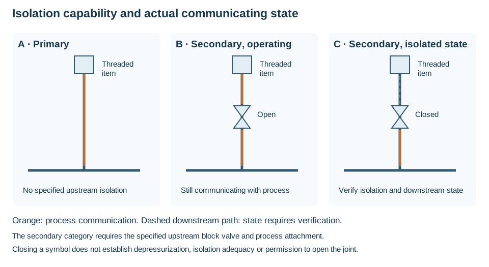
*Figure 3.2. Primary and secondary threaded connection capability and state.*
A primary connection in the selected sour-service route communicates directly with the process without its specified upstream isolation capability. A secondary connection has the specified upstream block valve attached to the process through its required welded, flanged or welded-fitting construction. This describes the physical arrangement. With the valve open, the secondary threaded item still communicates with the process and sees its applicable condition. The category does not mean that it is normally unpressurized.
Closing the valve changes the intended path but does not establish the downstream condition by itself. Verify the isolation boundary, retained contents and depressurization under the actual intervention procedure before relying on that boundary. An upstream valve connected through an ineligible attachment cannot be assumed to confer the required secondary category. The [structured topology and conditional matrix](assets/C03/c03-threaded-isolation.json) keep capability, operating state and adopted eligibility separate.
The following matrix records one selected historical route. Its *sour*, *severe* and *critical* categories depend on that route's separate service and material specifications; they are not interchangeable with the H₂S concentration descriptions in [Sour service](#chapter-c13). Critical-sour design is outside that specification's scope even though its table contains critical-column instrument entries. Establish the governing category and complete adopted basis before using a cell.
| Application / connection | Sour category | Severe category | Critical category |
| --- | --- | --- | --- |
| Piping/equipment primary | Conditional A | Excluded | Excluded |
| Piping/equipment secondary | Conditional A | Conditional A | Excluded |
| Instrument primary | Conditional B | Excluded, with specific exception route | Excluded |
| Instrument secondary | Permitted within adopted route | Permitted within adopted route | Table entry permitted; critical design needs its separate basis |
**Condition A** permits liquid-hydrocarbon/oil systems, or gas and multiphase systems within the stated ANSI Class 600-or-lower restriction. That class restriction is not a pressure in psi. It excludes service with fatigue-damage risk from vibration, thermal cycling or pulsation. **Condition B** carries consideration of a tapped blind flange that can be replaced after corrosion or thread damage. The primary-instrument exception applies where no reasonable alternatives exist and requires concurrence of the designated owner's representative. It does not grant an exception for piping/equipment or extend the table beyond its scope.
Whenever this sour-service threading route is adopted, also preserve the less-than-NPS-2 diameter, Schedule 80 minimum wall, cut-thread requirement and avoidance of liquid-water collection areas. Rolled threads require written engineering concurrence, suitable subsequent heat treatment, thread-root microhardness below 248 HV₅₀₀ and supporting test data. Applicable codes, standards and specifications remain simultaneous conditions. These requirements coexist with the component-wall and class restrictions above. An isolation category cannot override them.
## A flange seal depends on retained compression
Bolts pull flange faces toward one another and compress the gasket. The gasket must conform sufficiently to its seating surfaces to seal, while retaining suitable strength and recovery through pressure and temperature changes. Internal pressure creates separating effects. Flange rotation and external moments can redistribute compression around the joint. A high average bolt load does not prove that every part of the gasket remains adequately seated.

*Figure 3.3. The figure separates bolt-induced closure from pressure-induced separation. It is a qualitative section, with two representative bolts. It does not specify a gasket, flange geometry, bolt load or allowable pressure.*
For flange selection, choose the facing, gasket and bolting together. A flat full-face gasket, a ring gasket on a raised face, a spiral-wound gasket and a metallic ring in a machined groove depend on different contact arrangements. Gasket thickness, filler or core material, confinement and flange finish affect seating. Graphite can be useful in many hot services and unsuitable for a strongly oxidizing chemical environment.
PTFE offers useful chemical resistance and low friction but has its own deformation and temperature limits. Metallic windings, rings or jackets likewise need compatible materials. A gasket chosen solely by nominal diameter cannot establish the intended joint.
Bolt material determines strength and environmental/temperature suitability. Nuts, thread form and engagement, washers where specified, and lubrication affect the load generated during tightening. Low-temperature, hot and sour-exposure requirements can demand different bolting. High-strength bolting applied to a fragile flange does not automatically improve the assembly. The component’s permitted seating load and the actual procedure remain essential.
Torque is an indirect route to bolt load because friction consumes much of the applied effort. A change in lubricant, thread condition or nut-bearing condition may cause a previously chosen torque to produce a different load. Torque tables therefore belong to a defined bolting, gasket, flange and lubrication basis. A number copied from a superficially similar joint is not a complete procedure. Equally, forcing poorly aligned piping together can impose pipe strain and equipment loads even if the bolts reach their target torque.
### Relate the torque setting to its assumed preload
A useful approximate model writes tightening torque as a nut factor multiplied by nominal bolt diameter and preload. On a consistent inch-pound basis,
$$T=\frac{KDF_p}{12},\qquad F_p=\sigma_b A_t.$$
In these equations, $T$ is torque in ft·lbf and $K$ is a dimensionless empirical nut factor. Nominal bolt diameter $D$ is in inches, and bolt preload $F_p$ is in lbf. The selected tensile stress $\sigma_b$ is in lbf/in². The effective thread stress area $A_t$ is in in².
The factor 12 converts in·lbf to ft·lbf. The thread stress area is not the gross circular area formed from $D$. Thread form, material strength and the selected stress basis remain separate inputs. In consistent SI units the same model is $T=KDF_p$, with torque in N·m, diameter in meters and preload in N.
The inch-to-foot divisor does not carry into that expression.
The model explains a consequence of table selection. It does not determine the required preload. That selection must address gasket seating and retention, bolt strength, flange load and deformation, service and the adopted assembly procedure. Nor does an assumed $K$ prove the actual friction or scatter of a used assembly. Lubricant, threads, nut-bearing surfaces and any specified washers must match the basis. Lubrication intended for threads is not permission to lubricate a gasket or sealing face.
The tabulated torque bases also preserve assembly state. A selected procedure's tables apply at unpressurized, ambient conditions, with its stated 40–100°F ambient range. Internal floating-head bolting has a different lubricant, fine/coarse thread distinction and material/stress basis from general external bolting. A local higher stress fraction needing engineering disposition is not selected by choosing the largest table value. Before applying the stages below, preserve the joint identity and actual adopted procedure. This calculation supplies no warm or live-tightening permission.
### Match the ring, groove and assembly datums
A metallic ring joint depends on the selected ring profile engaging compatible groove surfaces. In the illustrated ring family, an oval profile can be used with the specified flat-bottom or rounded-bottom groove forms. An octagonal profile requires the flat-bottom form. That is a profile-compatibility distinction within those constructions, not proof that every oval ring, octagonal ring or flange groove is interchangeable. Match the actual dimensions, material and service basis as well as the profile name.
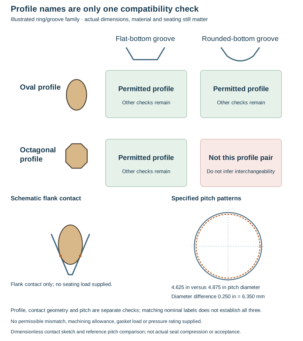
*Figure 3.4. The matrix records the illustrated profile relationships. The dimensionless flank-contact sketch and common-scale pitch patterns show separate geometry checks. A permitted profile pair still needs the actual ring/groove dimensions, material, seating and service checks. It is not a pressure-tightness result. [Structured profile comparison](assets/C03/c03-ring-groove-compatibility.json).*
Match pitch diameter independently of nominal size and class. The specified reference details at $4\tfrac{5}{8}$ in and $4\tfrac{7}{8}$ in do not coincide. That comparison supplies no allowable mismatch or machining permission; use substantiated compatible mating parts.
An assembled ring joint can retain a gap between the opposing flange faces after the studs are tightened. A drawing's approximate gap is not a required universal zero and is not a direct measure of gasket seating load. Likewise, a stud-length or assembly dimension stated for one construction may not apply to a lap arrangement with a different end thickness. Preserve the actual face/end/center references, ring geometry and bolt engagement rather than force an unfamiliar detail into another table's letters.
Replacement requires matched ring/groove geometry, facing and material, sound surfaces and the selected tightening basis. [Condition assessment](#chapter-c19) and [intervention](#chapter-c20) carry wear and restoration requirements.
### Compatibility includes material, facing and exposure
For a metallic ring, profile and pitch agreement leave the material question open. The ring must conform at the selected contact surfaces without unacceptable groove damage, and it must withstand the fluid exposure. An adopted ring-joint basis requires the ring to be softer than its mating flange unless an exception is qualified. Its carbon-steel route permits soft-iron or low-carbon-steel oval rings only up to 0.050 in corrosion allowance and selects another ring material above that allowance.
It requires the selected ring material to have a predicted corrosion rate below 0.010 in/year. These local quantities correspond to 1.27 mm allowance and 0.254 mm/year rate. Corrosion allowance is a thickness, while predicted corrosion rate is a thickness per year. A small allowance is not evidence of a small rate, and dividing an allowance by a predicted rate alone does not establish joint life or replacement acceptance.
Different local material portfolios specify different alloys and maximum hardness values; choosing the lowest or highest number across them would discard the applicable material/service basis.
A spiral-wound gasket's outer centering/compression ring and inner ring have different roles from the winding and filler. Their material and dimensions remain part of the assembled description. In a thin-wall pipe or large-bore flange, determine whether an inner ring protrudes into the actual flow bore. Nominal gasket size alone cannot resolve this interference. A qualified omission or different inner-ring metallurgy belongs to the applicable gasket basis. A confined facing can define another arrangement, so do not assume every gasket uses the same rings.
A conversion from a ring-joint seal to a specified spiral-wound conversion gasket is also a changed contact arrangement. One adopted route requires inner and outer rings, qualified adoption and a suitably finished flange surface where the replacement actually seats. Groove compatibility from Figure 3.4 does not prove that broad face's condition. Likewise, sheet, graphite, PTFE and metallic gasket temperature descriptions remain conditional on fluid, chemical oxidizers, facing and manufacturer pressure-temperature limits. A favorable filler temperature cannot rate the whole gasket or authorize an unqualified substitution. Keep replacement geometry and the actual service/material criteria with the change record in [Engineering records](#chapter-c21).
## Establish alignment and surfaces before tightening
Verify the matched flange/facing, gasket and bolting, with clean undamaged sealing surfaces. Check radial offset, bolt-hole rotation, parallelism and axial gap before tightening. Bolts must not be assumed to correct discrepancies. Changed piping position after unbolting requires renewed assessment of equipment strain and supports.
### Make the fit-up observations explicit
Radial offset, bolt-hole rotational offset, non-parallel faces and excessive axial gap describe different discrepancies. Measure the relevant geometry rather than record one undefined “alignment” value. For example, an adopted fit-up basis distinguishes a 1/16 in radial offset, a 1/8 in bolt-hole offset and a maximum 1/32 in difference between the widest and narrowest face gaps. These correspond to 1.5875, 3.175 and 0.79375 mm respectively. They are local fit-up criteria, not universal tolerances for every gasket or connector. The gap-difference measurement tests parallelism and is not the total axial separation.
That basis treats an axial gap above 1/4 in separately: if pulling the faces together requires more than 10% of the selected seating torque, assembly stops for investigation. It does not invite using the remaining 90% to straighten the line. Supports, dimensional fit, thermal position and changed equipment connections can explain the discrepancy. A compliant wrench reading after forced pull-up would still leave imposed piping strain and possibly a changed machinery alignment. Establish the cause and the permitted correction before completing the joint.
### Read each measurement in its own geometry
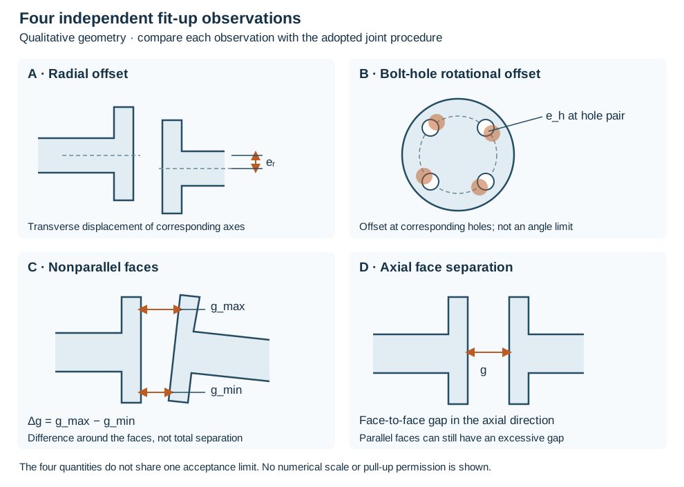
*Figure 3.5. Radial displacement, bolt-hole offset, face-gap difference and axial separation are separate observations. The geometry is qualitative. The selected local criteria and excessive-gap investigation rule remain those stated above. [Structured measurement relationships](assets/C03/c03-fitup-discrepancies.json).*
Measure bolt-hole displacement at the actual corresponding holes; it is not a specified rotation angle. Record the widest and narrowest face-gap locations on a common measurement basis. Parallel faces can still have excessive axial separation. Neither freely entering bolts nor a small gap difference establishes all fit-up conditions. Carry the observed geometry, permitted correction and verification into [assembly](#chapter-c17) and [records](#chapter-c21).
The assembly procedure must define compatible fasteners/gasket, permitted lubricant surfaces, tightening stages and gap/alignment checks. Crossing passes distribute initial compression; later passes address bolt interaction. One adopted sequence uses crossing passes at 30%, 60% and 100% of prescribed final torque, then two circular passes at 100%. It neither selects final torque nor applies to every joint or tightening technology.
Relaxation after assembly can reduce retained load. An adopted procedure can require a later pass after a specified resting interval for defined equipment joints, while applying different follow-up requirements to piping joints. Keep the type of joint, interval and service conditions with that instruction. Do not infer that every assembled flange should be retightened after the same time, or that tightening during pressurized operation is an ordinary extension of assembly.
Cast-iron, plastic and FRP flanges, isolation kits, lap joints and equipment closures require their specific load and assembly treatment. An isolation kit combines sealing with an electrical-isolation function. Sleeves and insulating washers are part of that arrangement. Bolting that preserves containment but bridges the intended insulation has not achieved both functions. A soft or nonmetallic component can be damaged by load tolerated by a steel assembly. [Construction](#chapter-c17) carries the selected assembly into field work and [Testing and readiness](#chapter-c18) establishes the boundary, proof and restoration.
### Keep the measurement setup, circle and acceptance basis together

*Figure 3.6. Flange measurement circles and individual-plane policy.*
Parallelism observations compare face gaps at equal distances from the centerline. Record the measurement circle with the widest-minus-narrowest difference. A difference taken at the outer rim cannot be compared directly with a limit defined at a smaller raised-face diameter. Lateral displacement of flange centerlines and bolt-hole orientation remain separate observations. Neither is the face-gap difference.
One adopted alignment procedure first requires bolts to enter freely. It then inserts the gasket and 25% of the bolts, with at least four. Those bolts are uniformly fastened with manual spanners only to remove free slack. That state establishes its general preassembled measurement.
It does not authorize pulling strained piping into alignment or replace the torque and investigation conditions above. Its rotating-equipment check instead uses loosely inserted bolting and its separate equipment criteria. Preserve the specified state in the measurement record. Substituting the general gasket/slack-removal setup would change that check.
The adopted procedure distinguishes two parallelism bases:
| Flange construction | Paired-face criterion and measurement reference | Consequence |
| --- | --- | --- |
| ASME B16.5 construction in this route | 2.5 mm/m at the actual measurement-circle diameter | Convert the slope quantity to a gap difference on that circle; rim tables use the corresponding rim diameter |
| ASME B16.47 construction in this route | 1.75 mm absolute at the raised-face outside diameter | A value measured at the larger flange rim needs the specified rim conversion, with its size, class and series |
These are historical adopted alignment criteria, not a statement of current standard tolerances. For planar face tilt, the difference scales with the diameter of the observation circle. Let D_m be that diameter in meters. In the B16.5 route, M = (2.5 mm/m)D_m.
Before using a rim-table value, resolve its criterion and units: the accompanying historical table headings use a per-diameter unit while the raised-face instruction states an absolute gap. Establish a consistent criterion, circle and table rather than silently changing a unit. These criteria do not replace the earlier local radial, hole-offset or gap limits.
A terminal flange on an individual spool is compared with its design plane before its mating part is present. A selected policy permits an individual departure of (M/2)√2, approximately 0.7071M, stated in rounded form as 0.7M. That policy relies on a statistical possibility that eventual mating departures may compensate. It is not a deterministic guarantee that every permitted pair meets M.
Worst-case accumulation answers a different question. If two independently bounded departures must guarantee a combined maximum M, their adverse sum must fit M. Allocating M/2 to each is one equal allocation under that specific two-term model. Do not use the statistical 0.7M policy as that worst-case allocation. [Terminal datums and dimensional closure](#chapter-c17) carries the actual design planes and accumulation method into spool manufacture. The [structured measurement relationships and teaching cases](assets/C03/c03-flange-measurement-circles.json) preserve the reference circles, setup and differing evidence claims.
### Preserve the distinct assembly configuration
An electrically isolating joint can conduct through the central gasket, through a stud touching either flange, or through an incorrectly assembled washer stack. Sleeves separate studs from the flange holes. Insulating washers separate the steel load-bearing parts at the nuts. Verify the actual stack and the intended electrical isolation as well as containment.
A selected kit combines one central gasket with sleeves, insulating washers and steel backup washers. Another adopted construction uses sealing gaskets on both sides of its central insulating gasket. Those configurations must remain separate. Adding or deleting a gasket changes sealing, bolt engagement and stack dimensions rather than simply improving insulation.
The temperature limit belongs to the assembled kit. For example, one selected kit's gasket, washers and sleeves are limited to 392°F, or 200°C, while its nonconductive anti-seize has a much broader stated application range. The lubricant's upper temperature does not extend the kit limit. Compatibility with oxygen, oxidizers, acids and other reactive service also requires the actual lubricant/material basis, not merely an electrical-resistance label.
HDPE and FRP joints demonstrate a different limit on bolt loading. A selected HDPE procedure uses the manufacturer's gasket-specific torque and pattern. It repeats tightening at least one hour after first tightening and at least four hours after the second. It follows the changing assembled condition over time. It is not a universal retightening interval for nonmetallic piping.
An FRP torque table based on a stated bolt stress cannot be replaced by the steel-bolt table merely because diameter matches. Observed flange flexing requires disposition, not continued loading until the wrench reaches a larger target. The material qualification in [Materials](#chapter-c02) and construction account in [Construction](#chapter-c17) carry those system and installation checks.
Equipment closures preserve another history. In a selected sour-service floating-head basis, an existing retrofit with B7M fine-thread bolting retains that thread form, while a new floating head uses a separately specified coarse-thread arrangement. The respective torque tables use their own effective thread area and lubricant basis. That internal construction omits washers. An external flange's washer arrangement is not carried inside by analogy. Keep the actual material, thread form and maintenance configuration with the exchanger in [Equipment arrangement](#chapter-c06) and its records.
Air-cooler header plugs also use a different description from a flange stud. Their selected torque depends on the nominal threaded plug diameter, header/plug material and gasket construction, not wrench-head diameter. A soft-iron gasket and a graphite-faced profiled gasket can have different torque settings at the same thread size. The facing needs protection during installation.
A selected instruction threads the new gasket onto the clean plug instead of pushing it over the threads. Lubricate the specified header threads while protecting the gasket-seating faces. A plug that does not run in by hand needs a qualified thread-condition decision. Greater tightening effort or automatic thread chasing does not establish restoration.
These are equipment-specific assembly conditions, not a new general flange torque table.
## External valve leakage has its own mechanism
Packing seals around a stem or shaft that must move. Compression loads the packing against the stem and box. Too little effective load permits leakage. Too much can increase friction, hinder movement or damage the assembly. Stem finish, straightness, corrosion, packing-box condition, gland alignment and the way rings are installed all affect performance. New packing in a damaged box is not necessarily a repaired seal.
A selected backseat can provide another stem-sealing contact near the fully open position. That contact changes a possible path toward the packing. The body and connected line can remain pressurized. The presence of the feature or the valve's wide-open position does not establish its leak-free condition, a complete isolation boundary or a permitted repacking intervention. Preserve the actual valve design and verified work state; [Intervention](#chapter-c20) develops the applicable preparation and limits. A statement about one valve's backseat cannot be applied to every bonnet or stem construction.
Manual block valves can remain at one position for long periods. Control valves continually move to regulate the process. Packing friction that is tolerable in one duty can create hysteresis or inadequate actuator force in the other. Changing from a low-friction packing to graphitic packing can therefore require an actuator reevaluation. This is a hardware/control interface, not merely a choice of emissions material.
Graphitic, fluorocarbon and combination packing systems provide different chemical, temperature, friction and fire-related behavior. Live loading uses springs, commonly disc springs, to maintain packing load as the packing consolidates or wears. It does not repair a corroded stem or make an incompatible packing suitable. Correct ring-by-ring installation can be important because compressing a stack inadequately can leave voids below a loaded top ring.
A bellows seal replaces the moving packing interface as the primary fluid barrier while it remains intact, often with backup packing. It can reduce external leakage but adds fatigue, cleanliness and replacement concerns. A claim of zero leakage must include the condition of that barrier and the duty for which it was qualified. It is not a permanent property of every operating state.
When leakage is observed, identify whether it is from the stem, bonnet, body joint, end connection or through the closed seat. Controlled adjustment under an applicable procedure, repacking, reconditioning and replacement address different causes. Repeated overtightening can damage a flange, gasket or packing and increase leakage. Online sealing or other temporary intervention has its own preparation and limits in [Repair and modification](#chapter-c20). It should not become an assumed substitute for a maintainable valve. [Operating integrity](#chapter-c19) develops monitoring, condition assessment and intervention sequencing.
### Install the packing as a defined set
Packing removal opens a fluid barrier and requires the isolation/depressurization basis in [Intervention](#chapter-c20). Inspect stem, box, gland and follower before selecting replacement. Corrosion, scoring, misalignment and unsuitable box geometry cannot be repaired by a lower-emission packing alone.
Identify the required ring material, dimensions, arrangement and installation method. In a selected flexible-graphite construction, braided end rings contain the die-formed middle rings and wipe the stem. A deep box can need a specified bushing, spacer or lantern-ring arrangement rather than additional packing rings. Compression applied at the top may not reach the lower rings adequately.
PTFE and combination constructions have different arrangements. The graphitic end-ring recipe cannot be transferred to them. Chemical compatibility, temperature and fire duty remain part of the selection. In particular, graphite's usefulness in many hydrocarbon duties does not establish compatibility with strongly oxidizing chemicals.
The selected ring construction controls installation access. Unsplit die-formed rings can require disassembly; a field-split route must be permitted for the actual product. Staggered splits avoid a continuous leakage path through an eligible split-ring set.
### Keep ring compression separate from stack compression
Use the manufacturer's instructions for the selected packing. Where a specifically adopted hand-operated-valve procedure uses the following fallback, it distinguishes three operations:
- **Die-formed ring precompression:** as each ring is installed, use the gland and spacer to compress it by 2–3% of its original height. This establishes contact through the depth of the set.
- **Completed die-formed stack compression:** after installing the full set, compress the stack by 20–25% of its original reference height. The denominator is the stack height, not one ring's height.
- **Braided graphite set compression:** under its separate five-ring route, install the first four rings. Tighten until resistance is felt. Install the fifth ring. Compress the completed set by 30%. This is not the die-formed precompression sequence.
Keep the reference height and stage with each percentage. Do not add percentages with different denominators or silently multiply successive reductions against a new reference. The actual procedure must establish the height used to set and verify its compression. Product-specific ring and set instructions can differ from this fallback, and an automatic control valve retains its separate friction, actuator and packing requirements. A higher compression is not automatically a better seal.
[Structured compression method](assets/C03/c03-packing-compression.json) preserves the separate stages and reference heights.
A manufacturer can instead specify gland-bolt torque to obtain the required packing condition. Use that torque with its actual bolt, gland and packing basis. The flange-stud model above does not select it. The selected readiness procedure must verify stroke and leakage under the prescribed state, with any permitted adjustment followed by renewed observation. Retain installed-set identity and its height or torque basis in [records](#chapter-c21); repeated tightening can increase friction or damage packing.
### Keep packing research tied to the tested assembly and service
Transfer packing results only where construction/formulation, ring set, compression/torque reference, stem/box condition, motion, fluid, pressure, temperature and leakage measurement represent the intended assembly. Ambient methane comparisons on new identical valves do not qualify worn valves in hot service. Historical studies found corrosion and stem finish influential; experimental finish/clearance levels are not manufacture tolerances.
Cycling increased emissions for most tested packings, and retightening generally improved measured response. No tested packing achieved zero measured emissions. Field comparisons need service severity and sample size: the highest reported medians were in the 700–1,050°F and 450–1,010 psig group. A ppm screening concentration is not an annual mass leak rate without the measurement/conversion basis.
The laboratory chart's “100% compression” label supplies no absolute height reduction or installation schedule; methane pressure and exact cycle count are not given. An ambient packing-pressure chart has a clipped protocol note and cannot supply a numeric gland-pressure selection method. [Structured historical research populations and limits](assets/C03/c03-packing-research-basis.json) retain these evidence boundaries.
Graphitic packing service compatibility is a separate gate. The historical incompatibility list includes strong oxidizers and specified conditions such as contaminated chlorine, oxygen above 600°F, phosphoric acid above 85%, sulfuric acid at 50–96%, fuming sulfuric acid and particular peroxide descriptions. It also lists butane/phosphoric-acid and sulfuric-acid/alkylate mixtures. These are listed exposures, not an exhaustive positive rating for everything omitted.
Several legacy chemical names or spellings and percentage conventions need actual substance identity established; a synonym cannot silently become a new concentration criterion. The structured companion retains the complete literal list and its qualifiers. Water service also raises graphite/metal galvanic-attack concerns. A favorable emissions test cannot remove them.
## Pressure changes can damage gas-loaded soft seals
Gas absorbed into an elastomer can expand during depressurization, causing swelling, blisters and internal cracks (rapid gas decompression, also called explosive decompression). CO₂ is important in the reported applications; chemical attack, hardening, abrasion and thermal aging can coexist with that damage.
The seal must therefore be selected for its pressure history as well as its steady operating state. A body O-ring can remain stationary while a stem seal moves, yet both can become gas loaded. Dynamic seals generally have greater susceptibility in the reported comparison. Motion also introduces friction, wear and changing contact conditions.
Cross-section size matters: a reported distinction identifies seal cross-section diameters above 0.15 inch, or 3.81 mm, as generally more susceptible than smaller sections. That is the thickness across the sealing section, not the outside diameter of the complete ring. It is a susceptibility observation, not a guarantee for smaller seals or a universal size prohibition.
The assembly changes the result. Clearance, confinement and available extrusion paths affect how the seal can expand and retain contact. A design that limits expansion and avoids an extrusion path can perform differently from another design using the same named elastomer. Changing the seal compound without assessing its installed section, groove, clearances and movement can leave the damaging mechanism in place. Conversely, success with one confined assembly does not qualify the compound in every larger or moving seal.
### Interpret a service history as an assembly history
A polymer family name does not fully identify a seal. Formulation, cure, hardness and actual manufacture affect its response. A reported sensitivity grouping can help identify questions, but individual formulations can perform better or worse than the grouping suggests. Temperature capability, oil and water compatibility, abrasion resistance and the required sealing motion remain simultaneous selection conditions. Greater decompression resistance is useful only in a compound and assembly that still performs those other functions.
**Table 3.3. Reported CO₂ service histories illustrate qualification boundaries.** Pressure reference and percentage basis are unspecified in these reports. The conditions are observations, not design limits or permission to substitute materials. [Structured cases and qualification method](assets/C03/c03-gas-decompression.json).
| Reported duty and conditions | Observed outcome | Decision the observation supports |
| --- | --- | --- |
| Oil production; 4,000 psi, 12% CO₂ in associated gas, 200°F | Very few decompression incidents | Preserve the fluid and operating history. “Few” does not establish immunity for all oil-production equipment. |
| Gas injection; 4,000 psi, 12% CO₂, 300°F | A 70-durometer fluoroelastomer compressor seal failed. A 90-durometer formulation of that family or another reported fluoroelastomer operated satisfactorily **with periodic replacement**. | The temperature, formulation, equipment and replacement duty belong to the result. The hardness scale and replacement interval are not given; greater hardness is not a general selection rule. |
| CO₂ production, pipelines and injection; 1,800 psi, 98% CO₂, 100°F | Several named elastomers failed in some equipment, while other equipment using the same elastomers worked successfully under the reported conditions. | Qualify the actual assembly and formulation. Family identity and nominal pressure-temperature conditions alone do not explain the different outcomes. |
A further pipeline history at 3,000 psi, 98% CO₂ and 100°F reports failures across the listed elastomer families while some assemblies using peroxide-cured compounds worked successfully. Assembly design was a major contributor. Another report at 4,500 psi, 98% CO₂ and 350°F describes the edge of the technology then being investigated. Neither report establishes a present universal material limit. The structured cases retain these additional distinctions without turning the histories into a compound catalog.
Do not calculate a CO₂ partial pressure simply by multiplying these reported percentages by the tabulated pressures. The pressure reference and composition basis have not been established. A valid partial-pressure input needs its own properly defined fluid and pressure basis. The low-pressure wording accompanying the reports also changes from “rarely” observing damage at or below 600 psi to a broader expectation of no problem. It does not supply a zero-risk threshold, especially for a different assembly or pressure history.
### Qualify the decompression path and the maintained configuration
Qualification needs the actual pressure-versus-time trace, including pauses, fast portions and repeated cycles. An average fall rate does not establish these. Reported damage can occur after one or many decompressions; the histories supply no universal safe ramp or cycle count.
Qualify the proposed compound and equipment together, using high/low temperatures and pressures, defined fluid composition and CO₂/H₂S partial-pressure bases, pressure histories, seal cross-section, static/moving duty, groove/clearances, formulation, cure and hardness. Chemical compatibility, friction and wear remain simultaneous requirements.
Comparable operating history must include equipment geometry and maintenance/replacement duty; periodic replacement is not evidence for an indefinite-life substitute. New or materially different equipment/CO₂ exposure requires decompression testing on actual equipment before selection commitment, with stated conditions and acceptance. These histories supply no universal test protocol.
Carry the qualified compound, assembly and required replacement/depressurization basis into [service selection](#chapter-c13), [readiness](#chapter-c18), [condition assessment](#chapter-c19) and [records](#chapter-c21). Substitution or changed pressure history reopens the affected qualification.
## Hub-and-clamp connectors trade compactness against service details
A hub-and-clamp connector uses tapered clamp surfaces to draw two hubs together. Assembly mechanically energizes a metallic seal ring. Its lips engage the internal hub surfaces, and pressure reinforces the sealing action. This differs from compressing a conventional flange gasket between broad faces. It can reduce size and mass in suitable high-pressure arrangements and simplify assembly where a large flange’s bolt access is difficult.
### Distinguish rib capture from lip engagement
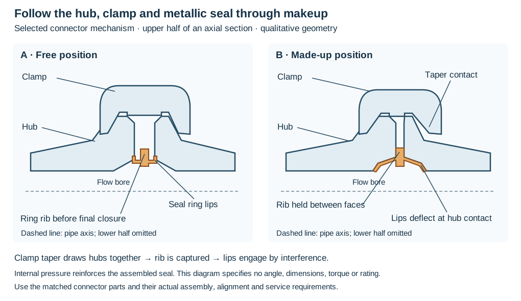
*Figure 3.7. Selected connector mechanism in a qualitative upper-half axial section. The clamp acts on the external hub tapers. The ring rib is captured between the hub faces while its lips engage the internal hub surfaces. The drawing establishes the relationships, not manufacture dimensions or assembly settings. [Structured parts and state relationships](assets/C03/c03-hub-clamp-makeup.json).*
The clamp draws the hubs together through their outer tapers. The ring's central rib is captured between hub faces; its lips engage internal hub surfaces with interference and deflect to seal. Rib capture locates the ring and is distinct from lip sealing. Mechanical makeup energizes the ring before pressure reinforces it.
Use matched hubs, ring, clamp and bolts with the selected materials, pressure-temperature and assembly basis. Protect internal sealing surfaces during welding/handling and preserve the hub-weld metallurgy. Clamp closure cannot correct unsuitable alignment, damaged lips or mismatched parts. The qualitative drawing supplies no clearance, deflection or manufacture dimensions.
Compactness does not remove chemical vulnerability. Dead-flow areas around the seal ring can prevent an inhibitor from reaching a susceptible surface. For water-saturated sour gas, brine or other corrosive service with this mechanism, a connector selected for high-pressure sweet service can suffer localized corrosion and premature leakage. That contrary service recommendation belongs beside the connector’s benefits. Select another compatible connection or establish a substantiated service-specific basis. Pressure capacity alone cannot settle it.
A joint that leaks after correct tightening needs examination of the seal, surfaces, alignment and service damage. Increasing bolt torque indefinitely does not correct those conditions. Reuse of a seal ring is an assessment under the applicable connector procedure, with the cost and consequence of a failed test or renewed leak considered. Opening the connection requires established isolation and verified depressurization. A clamp can retain pressure even after its fasteners have been loosened. Removal of bolts is not evidence that the boundary is safe to open.
## Jacketed assemblies contain two interacting systems
Jacketed piping carries product in a core and a heating or cooling medium around it. The core, jacket, spacers, terminations and component details must serve both containment and heat transfer. Their pressure-temperature conditions can differ, and their thermal movements need not be equal. A detail that transfers heat well in one arrangement can impose excessive strain in another.
Spacers maintain the annulus and affect the mechanical interaction between core and jacket. Terminations and connections can create cooler regions or different heat-transfer effectiveness. The heating medium must circulate through the intended jacket path. For liquid heating, an adopted arrangement introducing fluid at low points and removing it at high points helps fill the circuit.
For condensing vapor, high-point supply and low-point condensate drainage answer a different physical condition. Countercurrent flow and drainage slope are layout choices whose exact requirements belong to the selected system procedure. [Utilities](#chapter-c12) and [Thermal protection](#chapter-c14) develop the heating-system account.
The pressure boundary must also be checked during test. Testing the jacket puts external pressure on the core. A core designed for its internal product pressure may not withstand that differential. If $P_j$ and $P_c$ are the jacket and core pressures on the same reference basis, the pressure difference tending to load the core externally is $P_j-P_c$.
The adopted test procedure can require core pressurization or a core wall capable of the jacket-test differential.
Test and examination sequence preserve access. A procedure that requires leak testing of the core with its welds visible before jacket closure cannot be satisfied by testing only the completed outside assembly. Later access is limited, so fabrication and inspection planning belong with initial selection. Jacketed flange designs can have pressure-temperature details different from an ordinary standard flange. Their designation alone must not be used to assign an unsupported rating.
### Follow each boundary through the termination and local connection

*Figure 3.8. Jacket boundaries, termination and local annular connection.*
The core wall separates product from the jacket medium. The jacket wall and its termination contain that medium around the core. A jacket closure joins the outer boundary to the core while the product bore continues through it. A separable core flange or valve connection can interrupt the jacketed region without ending the product path. The selected local jumpover connects the adjoining jacket spaces around that interruption. Its seal and attachment are part of the jacket-medium boundary, separate from the core joint's gasket and bolting.
Spacers locate the core and maintain the intended annulus. The illustrated three-contact alternate leaves open sectors for passage and a specified clearance to the jacket. Use that alternate only when the engineering design or piping material specification calls for it. Its spacer material matches the core in that construction.
The contact, clearance, spacing, edge preparation and attachment affect both the passage and mechanical interaction. A convenient inserted piece cannot replace those requirements. Include spacer and termination effects in the movement analysis rather than assume the jacket and core can expand independently at every detail.
The local continuity panel uses one consistent condensing-medium arrangement: entry through the high jacket tapping, passage through the adjoining annular spaces and jumpover, and removal at the low drains, including the jumpover low point. Product direction is opposite the illustrated jacket direction. The drawing establishes connectivity and boundary locations. Slope, actual low points and drain construction must make that removal possible in the installed geometry. A liquid-heated arrangement with low introduction and high exit is a different state and routing basis. Do not apply the illustrated inlet orientation to it automatically.
An impingement plate near a selected steam entry and a siphon-tube drain for a selected vertical arrangement are separate construction alternatives. Fit either only where the selected detail and local physical conditions require it. They are not mandatory additions to every annulus, and a siphon tube does not establish drainage merely by being present. Likewise, a jumpover's tubing, nipples, couplings, insulation extension and any cleaned/seal-welded threaded region follow its specified jacket/valve size, material class and connection detail. Their catalog dimensions cannot rate another installation.
Retain separate core and jacket boundary/test states in the assembly record. [Thermal construction](#chapter-c14), [fabrication](#chapter-c17) and [readiness](#chapter-c18) carry insulation, access and test/restoration interfaces. [Structured boundary and connection relationships](assets/C03/c03-jacket-boundaries.json).
## A flexible hose is a complete pressure-retaining assembly
A hose can accommodate movement, temporary connection or transfer where rigid piping is inconvenient. It is composed of a fluid barrier, reinforcement or metallic corrugations, protective layers and end fittings. Chemical compatibility of the inner barrier, temperature, pressure including surge, vacuum and movement duty must be evaluated for the assembled product. The tube’s rating does not establish that a particular coupling and its installation have the same capability.
Rubber hose, layered composite hose and corrugated metallic hose behave differently. Reinforcement carries pressure loads. The lining or tube provides the chemical barrier. A composite construction has layered barriers and end-sealing details whose service and installation limits deserve specific scrutiny.
Thin barriers and unreliable end sealing can defeat containment even when the individual layers appear chemically suitable. Where the adopted hydrocarbon-service criteria exclude composite hose because of such leakage experience, it is not an allowable substitute. A permitted vapor-recovery application is a different duty. Metallic hose can accommodate bending but its corrugations and braid have fatigue and movement constraints.
Do not infer that a metallic construction tolerates arbitrary vibration, twist or high-velocity flow.
Route the hose to maintain the specified minimum bend radius and protect it from kinking, crushing, abrasion and excessive end loading. Bending flexibility is not permission to twist the assembly. Supporting a hose badly can concentrate bending at a coupling. Lifting or dragging by a connection can damage the component that retains pressure thrust.
Vacuum duty needs suitable collapse resistance rather than a positive-pressure marking. Electrical continuity or intentional isolation also depends on the transfer arrangement. Bonding alone does not answer every ship-to-shore potential difference.
Built-in, externally swaged/crimped and internally expanded couplings retain hose by different constructions. Their compatibility and assembly procedures are consequential: an incorrectly selected or installed fitting can leak or separate below the hose tube’s rated burst pressure. Service qualification may therefore include the hose, fitting and assembler as one combination. Steam, LPG, marine cargo and utility hoses need their own qualification and operating limits. A cargo-hose rule is not a rule for every flexible hose.
Identification connects the hose to its construction, rating, history and inspection. Examine the cover, reinforcement where exposed, coupling, distortion and evidence of leakage or damage using the applicable procedure. Tests and inspection can support a condition decision but do not erase damage or establish an unlimited life. Keep cleaning, storage, handling and rejection requirements with the qualified service. [Operating integrity](#chapter-c19) carries the condition-assessment sequence, and [Intervention](#chapter-c20) carries replacement and return to service.
## Preserve the joint’s duties when it changes
A component replacement can change far more than nominal size. New mass alters a branch or support load. Different face-to-face dimensions alter fit-up. Another seat or packing changes friction and leakage.
A different coupling changes restraint. A jacket or hose changes movement and test boundaries. Compare the actual substitute with the required functions and interfaces before installation.
# Chapter 4 — Plant arrangement, access and constructibility
## Arrange a working plant, not a collection of routes
Equipment removal, crane movement, valve operation, expansion and future construction require reserved space. Process connections, liquid head, gravity flow, pressure loss and proximity to utilities or transfer facilities constrain equipment placement.
Terrain, soil information, climate, drainage, transport connections and available land constrain the choices. A block plot plan can then reserve areas for process units, storage, utilities and waste handling in relation to one another. Its preliminary rectangles estimate functional areas. They are not final equipment clearances.
A process flow diagram establishes connections without establishing routes, access or supports. A three-dimensional clash check does not establish that an operator can perform the task.
Develop the area as a whole before finalizing each line. Routing the first connection in the shortest available path can occupy the corridor needed by several later connections. Additional bends, supports and elevations then accumulate around that early choice. A whole-area study can group routes by destination, preserve useful access and locate crossovers before the detailed arrangement becomes expensive to change. This does not require final data for every item at the outset. It requires awareness of which uncertain interfaces can alter the arrangement.
Spacing also serves containment of consequences. Separation between units can limit exposure to fire radiation or explosion effects and preserve emergency-response access. It can also permit maintenance or hot work in one area while a neighboring area remains in service. Greater separation can lengthen piping and consume land. Close grouping can increase exposure and congestion.
Compare those effects under the actual hazard and operating basis. Minimum spacing, convenient process proximity and adequate maintenance access answer different questions.
Some spacing bases group operations by their fire and explosion hazards to select relevant criteria. Such a classification does not replace hazard identification or analysis. Inventory, phase, pressure, temperature, unit size and interdependence can change the consequence of a release and the scope of the spacing decision. A distance copied from an equipment pair in another service can therefore miss the governing problem. Use the applicable spacing basis with the required hazard context. Do not treat a layout table as a universal safe-distance rule.
Escape to a designated safe area and evacuation from the installation need paths, destinations and capacity appropriate to the facility and personnel. A release, fire or obstruction can invalidate a routine passage. Coordinate safe support facilities and response access with the site hazards.
## Plan and elevation solve different problems
A plan view establishes equipment relationships, corridors and branch destinations. Elevation establishes headroom, gravity paths, equipment nozzles, pipe layers and platforms. A route that looks clear in plan may collide with a beam or lack the elevation needed to drain. A workable elevation may still obstruct a passage or withdrawal area. Review the two together rather than resolve one and assume that the other will follow.
Consistent routing elevations simplify the installation. Several unnecessary levels can require additional support steel and obscure which line crosses which. Grouping compatible routes at common elevations can reduce that complexity. Elevation changes remain justified where they preserve drainage, process head, equipment movement, access or the ability of another route to cross. The purpose is orderly physical behavior, not a rule that every line must remain in one layer.
At a rack or corridor junction, line sequence matters. Flat turns preserve a sequence of adjacent routes: a line on the outside can turn away before a line toward the center. If their destinations require the sequence to change, a crossing or another elevation may be needed. A long diagonal at the same elevation can block many adjacent routes, whereas a short local offset may cause little interference. Judge the effect on the other lines and on future connections. Do not select a diagonal solely because it saves one fitting.
Future expansion can reverse the preferred arrangement. A flat turn that is satisfactory at a dead end may obstruct a future through-route. An inexpensive elevation change during initial design can preserve that corridor. Conversely, raising every line in anticipation of unspecified expansion can add support and access burden without a useful purpose. Identify the probable future equipment, connection and reserved space, and record what the arrangement is preserving. Future allowance should represent a defined opportunity, not unallocated empty space that later detail design quietly consumes.
Equipment elevations require their own physical basis. A higher vessel can increase liquid head or accommodate gravity flow, while also increasing structural height, access and lifting requirements. A vertically structured arrangement can suit process and land constraints but creates several working levels and removal paths. A grade-mounted arrangement can simplify mobile maintenance while using more site area or longer connections. [Rotating equipment](#chapter-c05) and [vessels, heaters, exchangers and storage](#chapter-c06) develop the particular process and equipment mechanisms. The common layout method compares the resulting elevation, access and construction consequences without replacing those mechanisms with one preferred plant shape.
### Carry a routing choice through its present and future configurations
Start an area study with a connection list: each line's origin, destination, service and required route conditions. Group equipment that performs a related process function. Then examine the connections within and between those groups.
A process-flow symbol can represent several exchanger shells and can omit utility equipment; the equipment list and preliminary outlines therefore complete the physical population. Identify large, alloy or heavy-wall connections early because their loss, stiffness, weight and cost can make equipment placement consequential. The process sequence suggests proximity, while head, safety, support and maintenance can require a different arrangement.
Lay out the group before resolving one convenient connection. For parallel lines serving equipment on one side of a corridor, the outer destinations can often be reached by peeling off the outer lines first. Central destinations are then reached without crossing those departing lines. If that order cannot serve the actual destinations, compare a changed line order, equipment position or crossing elevation. The useful evidence is the whole set of connections in both plan and section. Counting bends in one line conceals the space and supports it demands from its neighbors.
Figure 4.1 isolates one consequence. The current line A reaches a destination south of the corridor. With no eastward through-route required at that station, its turn can stay at the common level. A defined future line B must pass eastward at that level. Its plan path intersects A's departure.
The two lines carry separate connections: the intersection is neither an intended tee nor an available empty lane. Keeping the turn flat would consume the identified future route.
An alternative changes A's elevation before it crosses B's lane and restores the required destination level afterward. The plan footprint still overlaps, but the section now separates the two envelopes. The drawing identifies only that topology; the raised level has no assigned height. The required separation must include actual pipe, insulation, flange and movement envelopes, together with the selected support and access arrangement. A drainage requirement, insufficient headroom, a nozzle condition or an unsuitable movement path can defeat this alternative. Moving the departure or equipment, changing the corridor sequence, or assigning the future line another evaluated level may be preferable.
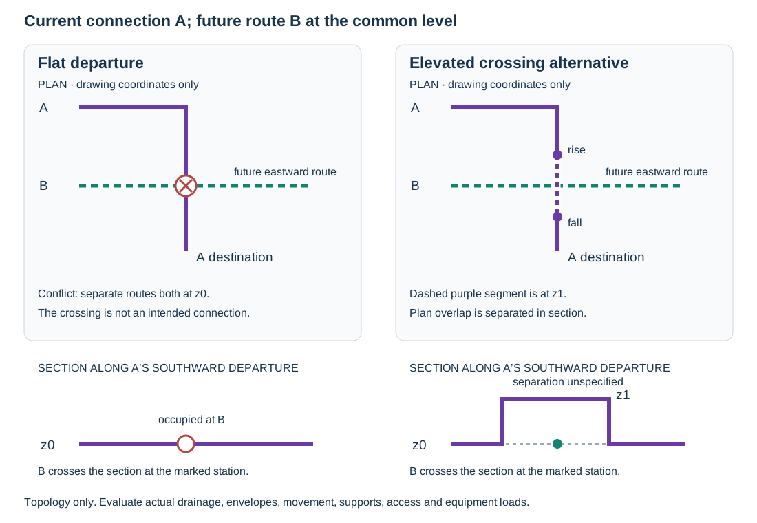
*Figure 4.1. An authored topology example derived from the area-routing method. A flat departure connects the current terminals but occupies the future line's common-level path. A locally elevated crossing separates the routes in section. Drawing coordinates are schematic, with no dimensions, loads or clearance acceptance supplied. [Structured geometry](assets/C04/route-comparison.json).*
Without the future route or another crossing need, the rise and fall add fittings, supports and installation work. Preserve the identified line and level only where the requirement warrants those additions. Large or stiff connections also require support and equipment-load evaluation.
A valve manifold offers the same reasoning at a smaller scale. A sequence of reducers can sometimes be replaced by appropriate branch connections, reducing the number of separate fittings and shortening the assembly. That alternative changes the joint and branch construction. The selected piping class must permit it, and valve access, support, inspection and assembly must still work. Fewer drawn fittings do not establish an acceptable branch or a lower lifecycle cost by themselves. The route and manifold comparisons both select complexity by the function it preserves.
### Revise the whole equipment group against the routes it must serve
A layout study carries equipment and connection identities through functional grouping, an initial plan, a line-run check and revision. Check gravity-flow elevation, alloy-route length, servicing/handling space and furnace separation/wind relationships.
The four panels below use an explicitly hypothetical equipment population and drawing geometry. D is a feed drum, P its pump, E a feed exchanger, F a furnace and R a reactor. C1 and C2 are compressors. V is a liquid-collecting vessel feeding exchanger G by a selected gravity route.
The process connections and identities remain constant across the panels. The example combines several layout constraints in one comparison. Its coordinates are drawing units, not plant dimensions, distances or approved equipment positions.
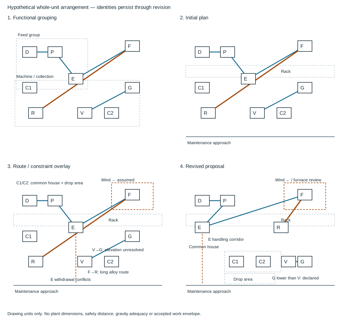
*Figure 4.2. Panels 1–4 keep the same equipment and process connections. The overlay names the requirements that cause the revision. The revised panel marks their proposed spatial responses. Plan proximity does not establish gravity head, furnace separation, adequate withdrawal clearance or a qualified alloy route.* [Structured equipment, routes and revision causes](assets/C04/unit-layout-iteration.json).
The initial plan separates the compressors and puts the reactor across the rack from its furnace connection. Exchanger G is beside V without an elevation commitment.
The constraint overlay makes five questions explicit. First, the V-to-G route needs its selected available head and draining geometry. Thus G's elevation must be resolved with V's liquid level and the actual losses. Second, E needs its axial bundle-removal and handling path.
Third, C1 and C2 are assumed to require a common operating and servicing house with a drop area reached from the maintenance approach. Fourth, the F-to-R connection is assumed to be an alloy route whose unnecessary length matters. Fifth, F needs its adopted separation and wind relationship to the unrelated hydrocarbon equipment. The wind arrow is an assumed teaching direction, not a site meteorological study.
The revised plan groups C1 and C2 along the maintenance side and reserves a connected drop area. It moves E so its withdrawal path reaches that side. It brings R nearer F to shorten the selected alloy route while keeping the furnace-separation review visible. It also assigns G a declared lower elevation relationship to V for the gravity route, rather than representing elevation by plan spacing. These changes are proposed responses to the stated constraints. Neither the shortened alloy connection nor the gravity arrow supplies the pressure-loss, flexibility, support or safety evidence needed to accept the result.
| Revision cause | Proposed response in the worked comparison | Consequential verification |
|---|---|---|
| Gravity flow from V to G | Preserve a declared lower receiving elevation and a draining route | Actual liquid level, pressure, losses, nozzle reference and operating range |
| Exchanger E servicing | Turn the removal corridor toward the maintenance approach | Bundle and cover envelopes, lifting/handling, disconnected piping and support states |
| Common compressor servicing | Group C1/C2 and reserve a connected drop area | Actual house, crane/handling path, equipment removal and operator tasks |
| Alloy F-to-R route | Reduce unnecessary separation and route length | Material/service basis, thermal movement, equipment loads and supports |
| Furnace exposure and wind | Retain the selected furnace zone and prevailing-wind relationship for review | Adopted safety spacing, site conditions, related/unrelated equipment distinction and access |
Changing one position can reopen several interfaces. Moving R closer to F may shorten alloy pipe while consuming access or changing exposure. Elevating or lowering G changes structure and work levels as well as head. Grouping compressors can share handling facilities while making one removal task interfere with another.
Carry the selected equipment locations, elevations, connection list and maintenance requirements into [technical continuity](#chapter-c21).
### Preserve line identity through turns and shared entry corridors
A rack turn must preserve the connection identities as well as a usable section. In the three-line example below, L1, L2 and L3 arrive in a declared order. A flat set of nested turns preserves their order along the departing rack when read in a consistent local cross-section direction. If the destination arrangement instead demands the order L3, L2, L1, the line identities must be traced through that permutation. Assigning a label to the nearest drawn line after the turn would silently change the connection list.
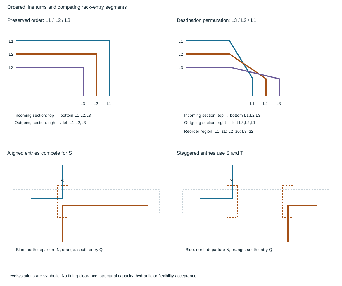
*Figure 4.3. The first pair compares a preserved line order with a separately declared destination permutation. The permutation lists each line's selected level through the reorder region. Plan intersections remain separate lines. The second pair compares two entries competing for one occupied segment against entries at separate stations. Station shift and levels have no assigned physical separation.* [Structured line identities, order and occupied segments](assets/C04/ordered-rack-entries.json).
Use the existing [plan-and-section crossing account](#c04-route-comparison) to evaluate a changed sequence. A level assigned through a reorder region is an interface requiring actual rise/fall geometry, fitting and insulation envelopes, drainage, thermal movement and support checks. Another solution can change the destination order or move the connection station. The diagram keeps L1, L2 and L3 bound to their destinations while those alternatives are compared. It does not establish the level heights or mechanically adequate routes.
Opposing rack entries have another constraint. A branch departing toward the north can occupy the same entry segment that a secondary rack from the south needs to reach. Aligning their structural centerlines may look orderly while leaving no independent route through that segment. In the comparison, the north departure and the south entry initially compete for segment S. The alternative places the south entry at another station and gives it segment T, while retaining both connection identities. A station shift can resolve this particular shared-corridor conflict without being a rule that every secondary rack moves one bay.
Inspect the occupied entry segments, the lines turning or rising there, and their support and future-route spaces.
A changed station changes line length, support positions and possible crossings elsewhere. The actual bent spacing and available width determine whether the shifted approach fits. The structural rack centerline does not reserve the pipe envelopes automatically. Confirm those relationships in the congested sections developed under [rack route planning](#c04-racks).
### Name the point and datum before comparing elevations
A location should identify the physical point, coordinate datum and units. Bottom of baseplate, vessel centerline, bottom of saddle and top of steel are different points. A shaft-center elevation cannot substitute for a baseplate elevation without the intervening equipment dimension. Likewise, a height above local grade is not automatically an elevation on the project datum.
Coordinate labels must retain their assigned datum: an English project datum of 100 ft and a metric datum of 100,000 mm are independent conventions, not a unit conversion. Compare physical separations within one convention or through an explicit datum mapping.
An offsite height above the high point of grade requires the applicable grade elevation before comparison with an absolute project elevation. Do not replace grade with a separately scheduled paving high point. Preserve grout allowances and the interfaces included in support or baseplate elevations.
The physical selection remains a coupled decision. Suction head, oil return, pulsation-bottle clearance, operator access and maintenance can govern different equipment points. Where independent lower bounds refer to the same point and datum, their maximum is the least elevation satisfying them all.
A preliminary sketch labeled with a suction-head height is a layout input. Available NPSH also requires liquid pressure, vapor pressure, operating level, losses and the selected pump reference. Use [the suction-head account](#chapter-c05) and [equipment interfaces](#chapter-c06) to establish those demands before deciding which bound governs. Changing the route or equipment can change the bounds and should reopen the comparison.
## Develop the pipe rack from the routes it must carry
A pipe rack combines piping with structural support and often cable trays, utilities and equipment. Its width, levels, elevations and bent spacing therefore depend on several interacting uses. A bent is the transverse structural arrangement that carries the rack at a support station. Longitudinal members can stabilize the structure and provide intermediate support or support for routes entering and leaving it. Their spatial positions need coordination with both the piping and structural design.
Start with a line-routing diagram on the plot plan. At this stage it shows which lines traverse each part of the rack and where they enter or leave. Exact offsets and interferences can remain unresolved. The diagram identifies congested stations. Develop a dimensioned section through those stations using line sizes, insulation, fittings, movements and required working clearances.
A count of lines alone cannot establish the width. A small line, large insulated line and line with a flange or valve occupy different envelopes.
Process piping is often grouped on lower levels with utility piping above it. Cable trays occupy a coordinated upper level or a separate level. This is a useful arrangement to examine, not a substitute for the actual service and access requirements. Electrical and instrument participants need to define tray space before the rack layers are fixed. Gravity or relief routing, equipment connections and process demands can require a different local arrangement. Keep overhead tray, pipe and equipment envelopes visible in the same section.
A simple packing calculation illustrates how a cross-section method works. Let $D_i$ be the effective outside envelope of line $i$ at the section. The required clear gap between adjacent envelopes is $G_i$. The edge allowances are $E_L$, $E_R$. All are measured in the same length unit. For an ordered row without overlapping envelopes,
$$
W=E_L+\sum_{i=1}^{n}D_i+\sum_{i=1}^{n-1}G_i+E_R.
$$
This is a geometric accounting identity. The engineering work lies in defining the envelopes and gaps. Insulation increases the outside envelope. A flange, valve operator, movement or removal task can govern a local section instead of the pipe body. The edge allowance must reflect its actual interface. A structural column, an adjacent layer or a reserved route is not free space merely because it lies outside the first pipe.
Reserve future capacity under the adopted planning basis and keep it distinct from present uncertainty. One rack-layout basis provides an additional 20% of space for future growth.
Where that basis is selected, preserve the allowance and its meaning in the rack arrangement. Define whether the allocation is a particular width, lane or level. Verify that branches, crossings and structures keep it usable. Do not silently reinterpret a space allowance as structural load capacity. Do not count the same space for unknown present lines and committed future lines.
Bent spacing addresses a different dimension. The pipes need acceptable spans in their relevant material, contents, temperature and insulation states. A structural column spacing does not automatically establish a suitable pipe support spacing. Road crossings or underground obstructions can require larger column gaps. Intermediate pipe bents or longitudinal support members are possible alternatives, subject to structural and pipe evaluation.
[Support and restraint decisions](#chapter-c10) develops the weight paths and mechanical states, while [flexibility and loads](#chapter-c09) develops the analysis. The layout must leave room for the selected supports and expansion arrangements. Fixing the corridor first can leave an impossible geometry that analysis cannot recover.
## Access is a task and a path
Clearance between two objects does not by itself establish access. Identify what the person or maintenance equipment must do, from approach through completion and removal. Reading a gauge, operating a valve, opening a manway, withdrawing a filter element and lifting a compressor component require different spaces and positions. Include tools, component travel and the place where a removed item is handled, not only the body of the person at the equipment.
For routine operation, locate controls and indications so the intended work can be performed from the selected access position. A valve handwheel that is visible across a pipe is not necessarily reachable with the required motion. A chain operator needs a clear hanging path. A local indication may need to be visible while a related control is adjusted. Elevated work can require a platform, stair or ladder according to the task, frequency and governing access basis. The presence of a ladder does not establish a suitable position for every maintenance job.
[Instrumentation and control](#chapter-c22) develops the measurement and control functions that these locations must preserve.
Maintenance adds larger envelopes. A heat-exchanger bundle needs a withdrawal corridor. A vertical pump or turbine part needs overhead removal space. A control-valve actuator may require access above it even when the valve body stays in place. A vessel manway needs room to open or remove the cover and support associated work.
The specific equipment chapter supplies the dimensions and removal mechanism. Layout keeps the path available through the surrounding installation.
A lifting path continues beyond the first vertical movement. A removed part must clear obstructions, travel to a laydown or transfer position and reach the transport or repair arrangement. For mobile equipment, consider approach, setup position, boom or swing clearance and the route out. For a fixed lifting arrangement, consider its travel and the load-transfer positions. Hydrants, lights, overhead lines, cable trays and later small piping can obstruct a path that appears clear when only the major equipment is drawn.
Compact placement can reduce lifting reach but increase congestion. A permanent lifting facility can simplify repeated maintenance but adds structure and interfaces. A temporary arrangement may be appropriate for infrequent work where the actual job and access permit it. The choice needs the part weight, removal procedure, frequency and available handling equipment. Do not turn a historical manual-handling number or crane-road dimension into a universal current limit. The useful method is to define and compare the complete task with its equipment and constraints.
Access also has a hazardous operating context. When another feasible arrangement removes the exposure, avoid frequent lifts over operating process equipment. Where the adopted layout basis permits an alternative protective arrangement, its purpose and extent must be explicit.
The operating and maintenance state matters. A route available during a shutdown may not be usable while neighboring equipment remains in service. A maintenance envelope should state which configuration it assumes, including any piping that is intentionally removed and how the remaining assembly is supported. [Operating integrity and maintenance](#chapter-c19) and [repair and modification](#chapter-c20) carry that reasoning into intervention.
### Build equipment spacing from the spaces that have different jobs
A center-to-center spacing can be developed from outside envelopes and intervening work spaces. Consider a horizontal drum beside an exchanger in a common transverse section. Let $D_d$ and $D_e$ be their effective diameters at the section, $A$ the clear operator-access strip, and $P$ the separately reserved piping-and-controls strip. With parallel, nonoverlapping strips and circular outside envelopes, their center separation is
$$
S=\frac{D_d}{2}+A+P+\frac{D_e}{2}.
$$
All quantities use the same length unit. The half-diameters reach from the equipment centers to their nearest outside boundaries. The variables $A$ and $P$ then account for the clear space between them. This tower-area spacing model keeps operator access and piping/control space as distinct contributions. Actual projections, insulation and attachments must be represented by the effective boundary or checked separately. A bundle diameter alone can omit the channel flange that governs the adjacent section.
If a control valve or actuator grows into the operator strip, the original arithmetic can remain correct while the reserved function is lost. Increasing $P$, reorienting the assembly or relocating the control are alternatives. Each changes a route, work position or support interface. A common strip can serve more than one task only when the assumed work states and sequences permit that sharing. It should not be counted twice as simultaneously available space. A regular operating passage and a shutdown bundle-pulling path may have different occupancy conditions.
The scalar sum also says little about vertical access. A platform can place the valve within reach while leaving a cover or filter withdrawal obstructed above it. An exchanger bundle needs its selected axial path and handling position. A vessel manway needs opening and work space on the correct side. Include the axial withdrawal, manway, cover and filter envelopes in plan and elevation, with the task and state, and follow the component through to laydown or transport.
Compressor cylinders illustrate another spacing model. One cylinder-removal arrangement defines removal length $C$ as the cylinder-removal distance plus a local allowance. The common gap $F$ between opposing tasks is $2C$ plus another allowance. This is a task-length account rather than the circular diameter model above. Sharing an area between machines does not establish that both cylinders can be removed simultaneously or that adjacent equipment may remain operating during the work. The actual cylinder, handling method and intervention sequence determine how the common space is used.
For elevated equipment, reserve the connected path from lift-clearance through the maintenance area and drop zone to the vehicle or repair position at grade.
A clear operating deck does not establish that the ground-level route is available. If maintenance takes place on the deck instead, identify the item size, weight and supporting-floor basis. The selected lifted load and hook geometry also affect the crane and building envelope. Structural adequacy cannot be inferred from the outlined clear area.
This approach lets compactness be evaluated rather than assumed. An elevated arrangement may use less ground area while adding structure, access and handling interfaces. A common crane, condenser or working area may justify longer piping because it simplifies repeated operation and maintenance. A grade-mounted arrangement may permit mobile handling while using more land or removable overhead piping. Compare these arrangements through their process connections, work paths and relevant states, and retain the reasons for the selected compromise.
## Structures organize work as well as support equipment
A structure can carry one or two items or much of a process unit. It may be open, sheltered or enclosed and may use steel or concrete. These choices affect equipment elevation, climate protection, access, lifting and installation sequence. Define the equipment and work requirements before fixing the frame, platforms and siding.
A frame that is adequate structurally can still obstruct a removal path. Bracing, beams, handrails and roof members need to be coordinated with manways, exchangers, instruments and lifting equipment. Removable sections can preserve a defined maintenance path, but their identity and removal/reinstatement needs belong in the arrangement and records. Openings left for a one-time installation should not be assumed to remain available for later maintenance if the final structure closes them.
Platforms should put the intended tasks within useful working space. Common platforms can serve several items and reduce separate access structures. Different elevations or process arrangements can make that solution unsuitable. Frequent operator attendance, occasional inspection and heavy-component maintenance are different functions. Choose the access arrangement and flooring for those functions and the applicable environment. Clearing the equipment outline alone does not justify a narrow platform.
Piping supports, fireproofing and structural details also occupy space. Fireproofing can enlarge a column or beam envelope and affect connections and clearances. Precast concrete members may occupy more space than an assumed steel frame. Supports for lines leaving a rack need actual attachment locations. Keep these interfaces in the model and installation information. An apparently minor late change to a brace or support can reverse the clearance on which a valve, instrument or removal path depended.
Shelters and enclosures require particular attention to maintenance. A roof can help the operating environment while limiting a lift. An enclosed structure may need a crane, designated drop zone or removable panel to handle equipment. Compare these configurations through the actual component path and selected handling equipment. [Rotating equipment](#chapter-c05) develops compressor case and nozzle arrangements; this chapter supplies the common method for evaluating their spatial and access consequences.
### Choose who carries the added equipment and working structure
Placing an exchanger above a drum can provide the required gravity-flow relationship while leaving two distinct support choices. An independent frame carries the exchanger, platform and drum at their required elevations through structural members to the foundation. A vessel-carried alternative places the exchanger and platform reactions into the drum shell, with the drum itself carried on concrete piers. The process arrangement can look similar while the load owner changes completely. Before choosing the vessel-carried alternative, consult the vessel engineer. Shell and local attachments, saddles or piers, foundation and connected piping must accept the added dead, operating, test and access loads.
An independent frame changes the motion reference. Drum, exchanger and structure may have different thermal movement or settlement, which their connecting line must accommodate. Vessel-carried equipment may move more closely with the drum at its attachment. This does not eliminate relative expansion of the exchanger or the gravity-flow pipe. Evaluate both alternatives through operating, test and maintenance states, including exchanger removal and lifting. Reduced separate steel is a possible layout economy only after vessel/structure capability and the full installation and maintenance cost are established.

*Figure 4.4. Separate schematic load-path alternatives for exchanger/platform above a drum. The gravity-flow connection and attachment construction are omitted. Actual relative movement, shell and frame capacities remain separate assessments.*
| Alternative | Added load path | Movement and intervention question |
| --- | --- | --- |
| Exchanger/platform on independent frame | Equipment and working loads → frame → foundation | Relative drum/frame/equipment movement; connected piping flexibility and removal support |
| Exchanger/platform carried by drum | Equipment and working loads → local shell attachments → drum supports → foundation | Local shell load and deformation; differential equipment growth; test and removal states |
| Coker penthouse/drill carried by drums | Work-structure and piping loads → drum attachments/shell → drum supports | Cyclic vessel movement and work loads; vessel design for the complete added duty |
| Coker work structure carried by elevated deck | Work-structure loads → independent steel → deck/foundation | Relative cyclic drum/structure movement and the pipe-support/flexibility interfaces |
The coker comparison is a separate cyclic-service application, not an enlarged version of the small drum/exchanger arrangement. In one alternative the penthouse and drill structure are carried from the drums. In the other the entire work structure is carried from the elevated concrete deck. The main operating-valve platform is deck-supported in both. Moving the drill load away from the drum may change required vessel wall and structural steel, but no thinner-wall result follows without vessel assessment.
Drum cycling makes relative movement and connected piping especially consequential in the independent arrangement. The work structure's operating, access and lifting duties require their own load basis and economic review. This comparison supplies no drilling or decoking procedure.
The load paths in [the process-carrier example](#c10-process-carrier-interface) expose the same principle: assigning a component a second supporting role creates new reactions and movement constraints. Preserve who receives those reactions in the equipment specification and drawings. Later platform enlargement or equipment replacement then reopens the affected vessel and structural checks.
## Nominal fit is not the ability to build
A drawing can show a geometrically correct connection that cannot be assembled economically in the field. Equipment and foundations have placement tolerances. Prefabricated spools have dimensional tolerances. Construction follows a sequence in which some interfaces are fixed before others. An arrangement that provides no practical adjustment or final connection can force rework even when its nominal geometry is sound.
A fitting-to-fitting connection illustrates the problem. If a vessel and pump do not arrive at their nominal relative positions, the compact connection can offer little opportunity to accommodate the difference. A deliberate construction spool can leave a controlled place to make the fit-up adjustment. The same issue arises at large equipment headers. The solution should provide an identified erection interface rather than rely on unplanned forcing of the connected assembly.
A construction allowance is not intentional cold spring. Cold spring introduces a specified prestressed geometry for a mechanical purpose. Field fit-up needs to preserve the accepted arrangement and equipment limits. If the adjustment changes the route, support contact or restraint behavior, reevaluate the affected interface. [Fabrication and construction](#chapter-c17) develops tolerances and assembly methods, and [mechanical analysis](#chapter-c09) and [supports](#chapter-c10) develop their mechanical consequences.
Construction sequence is itself a layout input. A central rack may need early erection and piping access before surrounding equipment makes the work difficult. Large modules, vessels and structures require delivery and lift routes. Temporary offices, storage, laydown, welding and assembly areas should not occupy the only approach to equipment needed during construction or maintenance. Coordinate the sequence and temporary facilities with the eventual installation. A workable final plot does not demonstrate that every construction stage is workable.
Field-run small piping, lighting and cable trays deserve explicit installation guidance where they can affect work. Major-equipment models may omit these details. A late hose, branch or bracket can block an operator's position or a removal corridor without creating a major model clash. Construction verification should examine the physical tasks and paths reserved by the design, not only whether the installed item follows its own drawing.
## Coordinate containment, drainage and the routes around them
Storage and spill containment reserve physical space for a function that is largely invisible during normal service. Tanks, dikes or secondary walls, drainage gradients, sumps, roads and transfer piping need to be developed together. A tank area can contain the required inventory geometrically but still have unsuitable access or an obstructed drain route. A piping crossing can defeat the intended boundary. [Storage and containment](#chapter-c06) develops containment forms and usable-volume sizing. Layout carries their placement, access and piping interfaces.
A compact concrete-wall arrangement and an earthen dike use space differently. The chosen form changes access across or around the boundary, the room for tank work and the route of product-transfer lines. Terrain can assist drainage while also constraining the enclosure. Under the selected service and drainage basis, decide where minor spills and rainwater go. Keep that path compatible with containment. Do not treat a convenient opening as an acceptable penetration without the required detail and service assessment.
Underground services share this crowded area with foundations, roads and rack columns. Gravity drains have an elevation requirement that pressurized routes may not share. Crossings and equipment foundations can interfere with both construction and later excavation or repair. Reserve the corridors and coordinate levels while the arrangement is still flexible. [Buried piping, pipelines and offshore interfaces](#chapter-c11) develops the distinct system engineering. A plant layout should not erase those distinctions merely because the routes share a site.
Emergency and routine access need to remain usable alongside these facilities. Place roads and work areas for their actual tasks and handling equipment. Preserve the relevant clearances around aboveground crossings. A nominally wide road loses function if a permanent obstruction occupies a needed setup position. An overhead route can also prevent the chosen vehicle or boom from passing. Evaluate the route as a connected path rather than a collection of local dimensions.
## Verify the spaces the design intended to preserve
Record provisional dimensions and dependencies on vendor geometry or handling method. A change to either reopens the affected arrangement. Clash and envelope checks do not establish pipe spans, structural loads, thermal movement, valve removal or human access.
During installation, verify control position and operation, removal/lifting/laydown paths, erection connections and access around racks, structures and containment. Include field-run piping, lighting and trays absent from the model.
Changes can consume reserved space gradually. A new instrument, a larger actuator, added insulation, another cable tray or future piping may each appear small in isolation. Assess the combined effect on the function of the corridor or envelope. A space allocated to a withdrawal path should not become a convenient permanent storage area without addressing that consequence. [Engineering records and human factors](#chapter-c21) develops the task-analysis, configuration and feedback route that preserves these decisions through construction and operation.
# Chapter 5 — Rotating equipment and its piping systems
## The machine and the connected system determine one another
Machine performance depends on fluid condition and connected-system resistance. Driver, auxiliary, operating and removal interfaces belong in the piping arrangement.
Centrifugal-pump flow depends on the selected machine, speed, suction conditions and system head. Horizontal, vertical and inline forms place nozzles, supports and maintenance interfaces differently.
Reciprocating pumps can be useful for small quantities, injection and viscous service. They impose cyclic suction and discharge flow; average duty does not establish instantaneous forces or fatigue response. Rotary displacement forms can give smoother flow and suit selected viscous liquids, subject to materials, solids and abrasion limits. Their discharge behavior differs from a centrifugal head-flow characteristic.
A positive-displacement machine can continue trying to move fluid against a restricted outlet. The discharge path and overpressure protection consequently belong in its system definition. Isolation, recirculation and relief must be evaluated for the selected machine and fluid. Returning relief flow to suction can introduce a heat input that also requires consideration. [Pressure design and protection](#chapter-c08) develops the applicable protective basis. Here the mechanism explains why the inlet, outlet and protective interfaces cannot be selected independently.
Drivers also change the system. An electric motor, steam turbine or gas engine has different utilities, startup behavior, exhaust or vent arrangements, maintenance access and response to loss of supply. A standby turbine-driven pump does not have the same readiness problem as a continuously operating motor-driven pump. The machine, driver and auxiliary system should be considered as an installation through its normal, standby, startup and intervention states.
## Head, pressure and shaft power answer different questions
Pump head expresses the energy added to a unit weight of liquid. A head in feet is not itself a pressure in psi, and the conversion depends on liquid density. Use the performance curve and duty of the selected pump to establish the relevant flow and head. A piping calculation does not create a pump curve.
A performance curve relates available head to flow for the stated machine, speed and impeller. Associated efficiency and power information describes the evaluated duty rather than one constant performance for all flows. The operating point has to meet the connected system's head demand, including its elevation/pressure requirement and flow-dependent loss. Changing route resistance can therefore change the operating flow even when the machine settings are unchanged. Changing speed or impeller requires the applicable performance basis rather than a curve selected only by pump name.
Read the curve's conditions along with its lines. Preliminary catalog information can support an arrangement study. The selected equipment data establishes the later connection and performance basis. A power curve stated for specific gravity 1.0 cannot be used unchanged for another liquid merely because the head axis still uses feet.
For customary units, the pressure-equivalent of an added head can be expressed as
$$
\Delta p_H=\frac{\mathrm{SG}\,H}{2.31},
$$
In this equation, $\Delta p_H$ is in psi and $H$ is head in feet of the specified liquid. The variable $\mathrm{SG}$ is its dimensionless specific gravity relative to the reference water. The approximate coefficient corresponds to 2.31 ft of reference-water head per psi. This expression gives a pressure difference equivalent to the head. Elevation and velocity contributions at the comparison points can be significant. In that case, total added head is not simply measured discharge-minus-suction pressure divided by liquid specific weight.
Those contributions belong in the hydraulic evaluation. The head definition and comparison points must agree with the performance data.
A discharge pressure also includes the inlet condition. Converting pump head to a pressure difference does not provide an absolute or gauge discharge pressure without the appropriate inlet and hydraulic information. Keep pressure difference in psi distinct from a pressure stated in psig or psia. [System definition and static head](#chapter-c01) develops these pressure-reference and elevation distinctions.
The hydraulic power delivered to the liquid is related to flow, density and added head. Pump efficiency relates that output to shaft input. In the customary-unit method,
$$
P_{\mathrm{shaft}}=\frac{Q\,\mathrm{SG}\,H}{3960\,\eta_p},
$$
In this equation, $P_{\mathrm{shaft}}$ is brake horsepower and $Q$ is flow in US gallons per minute. The variable $H$ is head in feet, and $\eta_p$ is pump efficiency as a fraction. The coefficient incorporates the reference-water and unit conversion. An efficiency of 90% is entered as 0.90. It is pump efficiency, not an assumed combined motor, gearing and pump efficiency. Additional driver or transmission losses need their own basis when determining the required driver input.
At fixed flow, head and efficiency, greater density increases pressure-equivalent and shaft power; lower efficiency increases shaft input. Actual viscosity, speed and operating point can change performance and efficiency, so use the selected curve and fluid basis.
### Read a pump curve as a linked set of duty quantities
A pump performance chart connects flow with head, impeller trim, efficiency, shaft power and suction requirement at a stated speed and fluid basis. A casing designation or nozzle size does not establish all those quantities. Begin with the actual chart identity, speed and test-fluid conditions, then follow the selected flow through each applicable ordinate. A trim curve is not a speed curve. An efficiency contour is not a constant-power line. Water NPSH does not establish a margin for a hot process liquid.
The selected historical inline-pump chart is for a closed impeller at **3550 rpm**. The recovered head curves are labeled 7¼-inch maximum impeller diameter, 6¾ inches and 6 inches. The power note states specific gravity 1.0. The NPSH curve is labeled **WATER**, with no test-water temperature stated. Its identity is preserved in the structured companion.
These particulars define the example. They supply no present product availability, vendor qualification or transferable curve for another casing or speed.
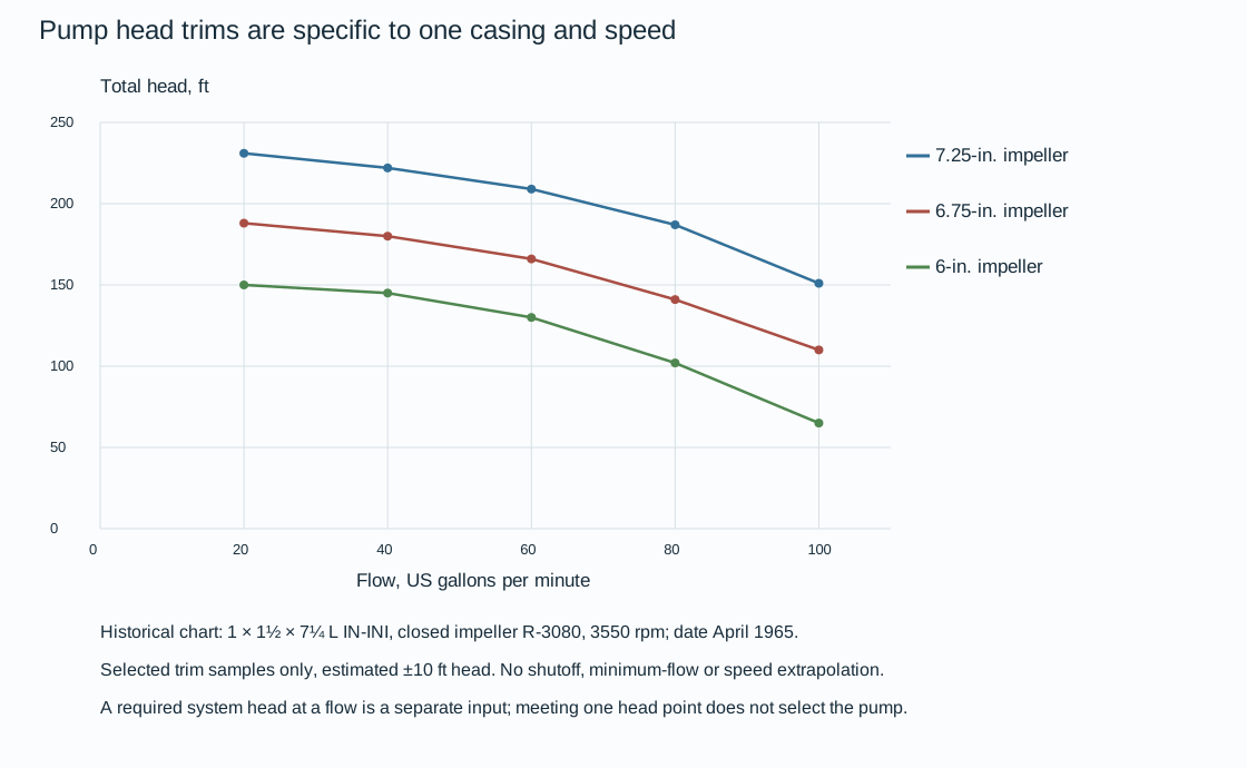
*Figure 5.1. Approximate selected readings at 20–100 US gpm on three impeller trims of one 3550-rpm chart. Straight joins interpolate only between saved samples on the same trim. They do not apply affinity laws or create untested trims. The author-estimated head reading allowance is ±10 ft. No shutoff or minimum-flow acceptance is recovered.*
For a hypothetical required duty of 60 US gpm at 185 ft of system head, the recovered curves give:
- Approximately 209 ft at the 7¼-inch trim;
- 166 ft at 6¾ inches;
- 130 ft at 6 inches.
The larger trim exceeds the assumed required head at this flow. The other two fall below it even within the stated graphical allowance. That comparison identifies a candidate for further duty evaluation. It does not make 60 gpm the operating point: the actual intersection with the complete system characteristic still determines the duty. Do not use excess head to justify an unexplained restriction or another speed without its performance basis.
Efficiency and power refine the same comparison. For the maximum trim at 60 US gpm and approximately 209 ft, the graphical efficiency is about 52%. The author-estimated allowance is ±3 percentage points. In customary units, the linked power calculation is
$$
P_H=\frac{Q_{\mathrm{USgpm}}H_{\mathrm{ft}}\mathrm{SG}}{3960},\qquad
\mathrm{BHP}=\frac{P_H}{\eta},
$$
In these equations, $P_H$ is hydraulic horsepower, BHP is shaft horsepower and SG is dimensionless liquid specific gravity. The efficiency $\eta$ is a fraction. Enter 52% as 0.52. At SG 1.0 this gives hydraulic power about 3.17 hp and BHP about 6.09 hp. Combining the head and efficiency reading allowances gives an illustrative BHP range of about 5.5–6.8 hp.
The original power-contour labels include 3, 5 and 7½ BHP. The calculated 60-gpm point lies between the 5- and 7½-hp levels. The native power series is calculated from recovered head and efficiency rather than claimed as a digitized continuous BHP contour family.
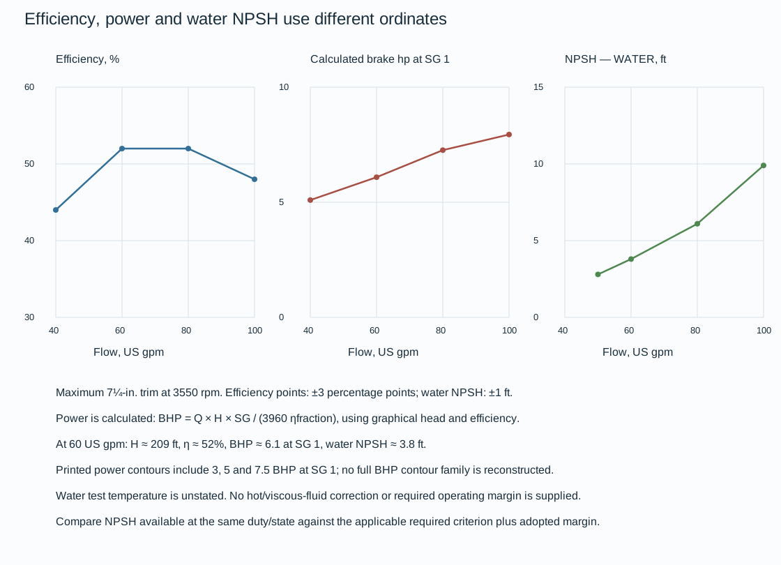
*Figure 5.2. Maximum-trim efficiency readings, calculated BHP at SG 1.0, and separately recovered WATER NPSH readings. The different ordinates retain their units. [Curve identity, selected head/efficiency/NPSH readings, power calculations and limitations](assets/C05/c05-pump-curves.json) preserve the basis; [drawing implementation](assets/C05/c05-pump-curves.draw.py) regenerates the native figures. These are historical graphical quantities with stated reading allowances, not equipment guarantees.*
The WATER NPSH trace gives approximately 3.8 ft at 60 US gpm and 9.9 ft at 100 US gpm, with an author-estimated ±1-ft reading allowance. A required head check therefore cannot substitute for a suction check, particularly when the duty flow changes. For the actual inlet pressure, elevation, vapor pressure and suction loss:
- Compare NPSH available against the applicable required criterion and adopted margin at the same flow and fluid condition.
The water trace does not itself state an acceptance margin or a hot-liquid correction. A hypothetical available NPSH of 3 ft at 60 gpm is below the nominal 3.8-ft trace reading. The approximate chart cannot establish adequacy near that crossing. Resolve current vendor data, the applicable criterion and the actual suction state before selection.
Fluid changes also reopen power and efficiency. Holding head, flow and efficiency fixed would make calculated BHP proportional to SG. This does not prove unchanged head and efficiency curves for a viscous or otherwise different liquid. The original SG-1 power note and WATER NPSH label must remain with their data. A changed speed, impeller, inlet state or system resistance requires the appropriate equipment and hydraulic evaluation. Carry the selected duty and its remaining data needs into the equipment, driver, piping and support interfaces instead of relying on one favorable pressure-head reading.
### Connect performance data to the installed configuration
A catalog size is a route to the correct data, not a description of every installation with the same nozzle diameter. One pump family identifies a size by discharge diameter, suction diameter and maximum impeller diameter, together with a series designation. Its performance curves then distinguish speed and impeller sizes within that family. Its outline data distinguish the motor frame, shaft extension, seal or packing arrangement and baseplate. Follow the connection between those identities. A curve belonging to one impeller or speed cannot silently supply the duty of another assembly.
Changing route resistance can change flow, efficiency, shaft demand and suction requirement. Do not carry the previous duty's efficiency into the revised duty without the selected performance basis.
A preliminary range chart can identify a family in which the desired head and flow may lie. It cannot supply the individual performance curve needed for final selection. The outline belonging to that family is another preliminary aid.
The selected driver frame can change the base length and shaft elevation. The selected seal can change quench, drain and recirculation connections. Water cooling can add an inlet, outlet and clearances that an air- or fan-cooled arrangement does not need. The drawing's optional, plugged and supplied connections must be interpreted as actual configuration choices, not as a list of every nozzle to connect identically.
Reconcile duty, machine/impeller/speed and driver requirements with nozzle coordinates, shaft height, baseplate, auxiliaries and removal envelopes.
A change to a larger motor frame or water-cooled bearing can invalidate a satisfactory foundation or utility route without changing the process line's nominal size. A certified outline therefore closes a specific provisional geometry. It is not a replacement for checking the affected connections and work envelopes.
The bearing variants illustrate the service consequence. In one horizontal pump family, a fan-cooled bearing serves a lower-temperature arrangement, while a water-cooled bearing is provided for higher pumping temperatures. In that particular bearing arrangement, cooling water enters at the lower tapped connection and leaves at the upper one. That flow path belongs to the selected bearing/jacket arrangement. It does not mean every pump needs cooling water or that a generic plant temperature chooses the variant.
The source of cooling, return condition, flow and readiness have to serve the actual machine. Loss of that cooling becomes another operating state for the equipment and its connected system.
A vertical pump adds a column and shaft arrangement to the choice. Oil and fresh-water lubrication alternatives are distinct in the illustrated multistage family. Its packed tension-nut detail is for fresh-water lubrication, and an additional column is a specific option.
That family's rating sheet also calls for efficiency reductions of 2, 1.5, 1 and 0.5 points for two, three, four and five stages respectively. These are local rating adjustments for that family, not a universal relation between stage count and efficiency. Keep them with the exact rating data and interpretation before a shaft-power calculation. A percentage-point reduction is different from multiplying efficiency by a percentage reduction.
Carry the selected lubrication, stages and column into the handling and pull-out arrangement.
The pump's auxiliary connection map should distinguish the function and medium of each selected circuit. Cooling water can remove heat from a bearing, stuffing-box region or high-temperature support pedestal. Its outlet is a cooling return.
Mechanical-seal circulation has a different path. In a selected process-derived arrangement, fluid taken from the pump case passes through the seal circuit. It returns to the pump stream or through the seal into the pump's internal clearances. In an external-medium arrangement, a separately supplied compatible clean fluid serves the selected seal duty. A clean gas oil is one hydrocarbon-service example, not an approved fluid for every seal or pumped product.
Gland quench, lantern-ring flush and seal circulation are not synonyms for bearing cooling. Their connections cannot be completed by attaching the nearest available water supply. Establish the actual medium, pressure and temperature, inlet source, required function and permitted outlet for each selected circuit. A vendor harness can cover some connections while plant piping covers others. Reconcile both drawings and the system diagram so a required connection is neither omitted nor duplicated. The pipe's small size does not make its loss of function unimportant to the machine.
Keep drains and leakoffs separate from those utility returns. The pump case vent and drain, stuffing-box drain and baseplate drain have different origins. A steam-driven installation can also have valve-stem leakoff and a steam-chest drain. Identify their collection or disposal conditions and the actual isolation/maintenance state. A pipe leaving the equipment is not automatically a cooling-water return.
Above-grade supplies in an illustrative layout also do not exclude a buried utility system. The selected connection must remain accessible and serve its actual source and destination. Utility loss, shutdown and restoration should be evaluated for the configured circuits, rather than inferred from the presence of a completed harness.
A common spare introduces a further configuration. When the middle of three pumps serves either of two duties, an arrangement based on the larger duty can provide a practical common machine. In that arrangement, top-suction geometry can simplify its routing. The spare still has to serve both actual fluid, pressure, temperature and performance conditions.
Its selection is not established by maximum volume alone. Describe how the suction and discharge connections select the intended service and how the inactive path is controlled. Different process compositions or operating pressures can turn a convenient shared route into an unacceptable cross-connection unless the selected configuration preserves separation.
A concrete common-spare topology makes the service-selection problem inspectable. In the considered arrangement, the service-B suction joins the service-A line downstream of its block valve and upstream of the common strainer. On discharge, the service-B branch joins downstream of the common check valve. Either selected suction therefore passes through the shared element, pump and discharge check before reaching the selected outlet branch. Selection has to occur on both sides of the machine. Changing only its inlet can deliver the right fluid to the wrong destination.
*Table 5.1. Communication to establish for a two-service common spare.*
| Defined state | Intended suction and discharge path | What the actual configuration must establish |
| --- | --- | --- |
| Serving duty A | A source → shared strainer → spare → common check → A destination | Required A duty and compatible supplies; B does not form an unintended communication path |
| Serving duty B | B source → shared strainer → spare → common check → B destination | Required B duty and compatible supplies; A does not form an unintended communication path |
| Unavailable for maintenance | Selected intervention boundary; spare removed from both service duties | Actual isolation, depressuring/draining, remaining support and restoration basis; neither duty credits unavailable spare capacity |
| Transition between duties | Controlled change from one defined path to the other | Actual contents, compatibility, pressure and thermal states, valve selection and readiness; no unexamined overlap between services |
This table defines engineering questions for the selected topology, not an operating valve-lineup procedure or an automatic interlock design. The common check serves its selected reverse-flow function. It does not choose the suction source or discharge destination and does not establish complete maintenance isolation. Check the actual block valves, available utilities, control and transition arrangements in the complete system. A common spare can reduce installed equipment while making those shared interfaces consequential to both duties. [Structured state data](assets/C05/c05-common-spare-states.json).
Pressure-boundary identity belongs in the same data chain. A selected pump can have suction and discharge nozzles of the same rating. Its manufacturing test exposes both sides to a common test pressure. This can apply even where the adjoining suction line has a lower class. That example explains why normal suction pressure alone may not determine the nozzle connection. Establish the actual machine's manufacture/test and maximum-pressure basis, flange face and class at the connection.
It supplies no universal equal-rating or test-factor rule, and says nothing about acceptable piping force or moment. The terminal-load account below remains a separate evaluation.
## Suction conditions decide whether the liquid reaches the impeller usefully
Suction piping is not simply the low-pressure half of the installation. It supplies liquid in a condition that the pump can handle. Elevation and vessel pressure can provide head, while piping resistance consumes it. Liquid vapor pressure depends on its condition. If local pressure falls sufficiently, liquid can form vapor. Subsequent collapse of vapor bubbles as pressure recovers can cause noise, loss of head and capacity, and damage near the impeller inlet.
Entrained gas and trapped gas pockets can also interfere with liquid delivery, but should not be confused with the particular vapor-bubble mechanism of cavitation.
Available net positive suction head describes the system's head above the liquid vapor-pressure condition at the selected pump reference. Required NPSH is a property of the selected pump under its specified test and operating basis. They are different quantities. Increasing available head by changing vessel elevation or reducing suction loss does not change the supplier's requirement. Changing the pump or duty can change that requirement.
For a large vessel feeding a pump, the following available-head account assumes negligible velocity at the liquid surface and uniform liquid density:
$$
\mathrm{NPSH}_a=
\frac{p_s^{\mathrm{abs}}-p_v(T)}{\rho g}
+(z_s-z_r)-h_L.
$$
In this equation:
- $p_s^{\mathrm{abs}}$ is absolute pressure above the liquid;
- $p_v(T)$ is liquid vapor pressure at the evaluated temperature;
- $\rho$ is liquid density;
- $g$ is gravitational acceleration;
- $z_s$ is liquid-surface elevation;
- $z_r$ is pump reference elevation;
- $h_L$ is suction-system head loss to that reference.
With pressures in Pa, density in kg/m³, $g$ in m/s² and elevations and loss in meters, available NPSH is in meters of that liquid. The pump reference and evaluation convention must agree with the supplier's required-NPSH data. A vertical pump can place the relevant inlet reference below the visible driver elevation, so use the actual machine arrangement.
The equation makes a layout decision inspectable. Higher surface pressure or liquid level can increase available head. Higher vapor pressure or suction loss reduces it. A low operating level can therefore be more important than the vessel's maximum level. A warmer condition can consume suction margin even with unchanged piping. A dirty temporary strainer can increase loss without changing the nominal line size.
Over the applicable operating range, compare available head with the selected pump's requirement and adopted margin or acceptance basis. Do not copy a vessel-height example as though static height were the only contribution. Surface pressure, vapor pressure, loss, operating level and the pump datum remain part of the method. A short suction route is advantageous when it reduces loss without defeating flexibility, access or another service requirement. [Vessels and equipment interfaces](#chapter-c06) supplies the connected liquid-level and equipment-elevation context.
## Suction and discharge arrangements have different priorities
Locate the pump and suction source so that a practical, short route can serve the required inlet condition. Avoid unintentional high points that retain gas and arrangements that unnecessarily consume suction head. Reducer orientation, elbow approach and the selected nozzle direction should be reviewed as a fluid path, not only as a collision problem. End-suction, top-suction, side-suction and vertical arrangements require different approach geometry and support.
A larger connecting line can be appropriate even when the pump nozzle is smaller. The piping size follows service loss, flow and mechanical needs. The nozzle follows the selected machine. Make the transition with the intended flow condition and access in mind.
A nozzle mismatch does not mean the machine should automatically be redesigned. It also does not make a reducing flange always an acceptable substitute for a gradual transition. Preserve the supplier and service requirements at that interface.
Close suction and discharge nozzles can cause the adjoining piping envelopes to collide. Compare offsets and reducers together. A suction offset can add loss and disturb the approach. A discharge arrangement may offer more freedom for that particular installation. This is a conditional routing comparison, not a rule permitting every discharge offset or forbidding all suction changes. Check the actual pump outline, line sizes and hydraulic and mechanical consequences before fixing the arrangement.
Suction valves and strainers also influence space and pressure loss. A conical strainer can require a spool long enough to insert and remove it. A flat or basket form has a different envelope and flow area. A tee-type temporary strainer can provide an alternative removal route.
Provide physical access to install, inspect and remove the selected type. Include the piping or flange intentionally opened. A drawing showing the strainer symbol does not establish that the element can be withdrawn.
### Select the strainer with its removal path and suction condition
A temporary strainer creates a tradeoff between protecting the impeller and preserving the liquid delivery on which the pump depends. Its useful flow area, particle-retention requirement, clean loss and expected debris loading belong with its pressure boundary and withdrawal envelope. A plate that fits between the flanges can be mechanically convenient while presenting a restrictive flow path. A longer basket or cone can offer more perforated surface while requiring space inside the adjoining spool or fitting. A suitable clean arrangement can become hydraulically unfavorable as debris fills it.
One particular flat-plate pattern uses 5/16-in holes on 7/16-in staggered centers and is described as having 46% open area. That pattern illustrates the limitation of a flat element. It does not prescribe a particle size or establish the loss of every flat strainer. The basket and conical families considered here instead offer short and long elements labeled 150% and 200% open area. Their increased surface is obtained through three-dimensional geometry and length.
Establish what area the selected product's ratio references before comparing those labels with a flat-plate perforation percentage. Neither a catalog percentage nor a gross vessel opening supplies a pressure-loss coefficient for a clean or fouled element. The selected duty still needs the actual mesh or holes, flow, liquid condition and permitted suction loss.
*Table 5.2. Strainer geometry changes the flow and intervention problem.*
| Form | Geometry and interface to establish | Consequence for selection and removal |
| --- | --- | --- |
| Flat plate | Perforated plate and actual mating flange-face arrangement | Short axial envelope; limited perforated area can be rapidly restricted by debris |
| Basket | Extended perforated body, attachment ring, diameter and length | More surface needs room inside the adjacent pipe; withdrawal can require opening and moving a spool |
| Conical | Cone length, ring, fitting clearance and selected mesh or perforation | A cone may not fit between an elbow and nozzle flange without a suitable spool; check the insertion as well as withdrawal path |
| Tee-mounted element | Element and guides within a tee or body, access blind and drain arrangement | Withdrawal through the access opening can leave the pump-side connection assembled; the access branch and lifting/handling space remain necessary |
Flange compatibility is part of this choice. The considered basket, cone and plate details distinguish flat or raised faces from ring-joint mating arrangements. Their ring and rebate construction cannot be exchanged simply because nominal pipe size matches. Use the specified flange face, class, gasket and element attachment together. A flange joint used to retain a temporary element also needs its restored arrangement defined for the state after the element is removed.
Now consider the actual break-out task. At an end-suction pump, a cone can need additional axial room between the elbow and weld-neck flange. Determine that space from the selected element rather than treat an illustrative spool length as a general minimum. If removal requires disturbing an inline spool, establish:
- Which flanges open;
- How the spool and remaining piping are carried;
- How the pump connection is restored without forcing alignment.
A tee-mounted strainer offers an alternative: removing an access blind permits element withdrawal while the main connection remains assembled. That can avoid one source of realignment work, but does not eliminate isolation, depressuring, draining, element handling or inspection of the opened boundary.

*Figure 5.3. Authored conceptual intervention layouts after the selected isolation, depressuring and draining procedure. The inline element is removed with a break-out spool. The tee element is withdrawn through an access opening. Supports and isolation devices are not a completed design in these schematics. The choice changes which assembled alignment and load paths are disturbed. [Structured data](assets/C05/c05-strainer-removal.json).*
Monitoring and removal should follow the startup condition. Debris capture protects the machine while increasing the element's resistance. A loss increase can consume available suction head even when vessel level and line size remain unchanged. Use the selected monitoring and intervention basis, with the inlet and outlet measurement locations identified where differential pressure is used.
Replacing a temporary element after cleaning, removing it permanently, or retaining a permanent strainer are different configurations.
Record which was restored and check the intended flange, support and inlet path. Calendar time alone does not establish that debris loading or removal conditions are acceptable.
Discharge piping must serve the pressure-producing side of the system. Check and block valves, pressure measurement and any required recirculation or protection have distinct functions. A check valve can limit reverse flow in its selected application but is not automatically a complete isolation or protection system. A pressure indication upstream of an intervening valve can describe a different state from one downstream.
[Components and joints](#chapter-c03), [pressure protection](#chapter-c08) and [measurement and control](#chapter-c22) develop those functions. Their positions and access have to work in the actual equipment arrangement.
[Cleaning and readiness](#chapter-c18) and [operating integrity](#chapter-c19) develop the startup and restoration basis.
## Hot piping requires a coupled hydraulic and mechanical decision
Hot suction piping can be hydraulically attractive when short and direct but mechanically unfavorable when it cannot accommodate relative movement. Additional elbows and length may provide flexibility while increasing loss. Increasing diameter to reduce that loss changes stiffness, weight and the nozzle interface. The arrangement must be reevaluated after the change. A previous flexibility result does not apply unchanged to a revised line size.
Begin with the equipment and system movements, not only the fluid temperature. The pump, connected vessel and header may move differently. A common header can be hot while an idle pump branch remains colder. The combinations depend on operation. Evaluate the applicable branch and standby states. Do not assume both pumps and all connecting pipes always reach one uniform temperature.
Support placement changes both dead-weight loading and movement freedom. A support near a nozzle can relieve weight and its bending moment, but a restraint at that point may oppose thermal displacement. A support farther away may allow more flexibility while leaving a longer unsupported mass near the terminal. [Flexibility and loads](#chapter-c09) and [support and restraint decisions](#chapter-c10) evaluate those consequences. This chapter supplies the actual machine, piping geometry and operating states that the evaluations must represent.
Special arrangements, including selected spring-mounted equipment, can permit particular movement paths. They also change the machine's support and alignment interfaces. Do not treat a moving support as a generic cure for hot piping. Establish the supplier's permitted movement and nozzle conditions, the foundation and driver interfaces, and the actual cold and hot configurations. An arrangement that accommodates vertical growth may still be unsuitable for horizontal relative movement.
Recheck suction loss/available head and pipe/terminal behavior after any route, diameter, equipment-position or support change. Preserve one evaluated geometry, restraint configuration, equipment movement and installation-setting basis.
Standby changes a slurry suction line's fluid state as well as its temperature. A large flexible loop can provide needed movement while increasing the length that remains dormant when its pump is not running. In that branch, the normal flowing condition no longer explains how solids or deposits will accumulate or how the line will be returned to service. Keep the dormant volume and service behavior in the comparison alongside nozzle loading and flexibility.
One selected hot-slurry arrangement separates the vessel bottoms outlets for the primary and standby paths early in the vessel design. This reduces the shared dormant branch that a long common suction arrangement would otherwise create. That is a joint vessel, process and piping-layout choice, with its outlet geometry carried into the basic equipment specification. It is not a general instruction to add a nozzle or split every suction line. The resulting branches still need their actual hydraulic, thermal, support and nonoperating-state evaluation. Under the selected service basis, establish stagnant volume, heating/draining and standby readiness for each path.
A shorter dead leg is useful only while the revised route preserves the required inlet and movement conditions.
## Pressure rating does not establish nozzle-load acceptance
Pressure containment, piping loads and machine alignment are different questions. A pump nozzle flange can match a pressure class while the connected pipe transfers unacceptable force or moment to the machine. Dead weight, thermal movement, support reactions, settlement and dynamic effects can all influence terminal loading. The load path continues through the nozzle and casing to the machine and supporting arrangement.
Use the selected machine's allowable-load basis and applicable project criteria. Generic preliminary force estimates can help layout development, but they do not become manufacturer acceptance simply because they use the same units. Force-only limits do not describe a complete force-and-moment interaction. The formal evaluation needs the applicable directions, combinations and equipment conditions. [Mechanical analysis](#chapter-c09) develops that comparison. This chapter keeps it connected to the machine being installed.
An integral inline pump and driver can reduce some relative-alignment interfaces compared with separately mounted equipment. That feature does not mean piping loads and movement are unlimited. Horizontal, vertical and multistage forms still need their actual support, removal and supplier requirements. Preliminary envelope data can support early studies, but final connections and maintenance dimensions should reflect the selected equipment.
Installation should preserve the configuration that was evaluated. Forcing a misaligned pipe connection into place can load the machine before it operates. An intended cold-spring arrangement, where permitted and specified, is a different engineering decision with an evaluated geometry. Where the governing basis prohibits cold spring or reserves it to owner approval, follow that restriction before selecting an installed prestressed geometry. Adjustable supports and construction spools should accommodate their defined erection purpose without silently introducing another prestressed state. Recheck an actual field alteration that changes support location, route or restraint.
The maintenance state also changes the terminal arrangement. Removing a strainer spool, a valve or compressor cover can remove a support path or expose a partly connected assembly. Define how the remaining pipe and the item being removed are carried. Correct operating nozzle loads are not proof of stability during partial disassembly. [Work envelopes and constructibility](#chapter-c04) and [intervention and modification](#chapter-c20) develop the associated spatial and work decisions.
## The driver adds its own utility and removal interfaces
An electric motor requires the selected electrical supply and equipment arrangement, with any specified cooling and the access needed to maintain or remove its parts. The motor envelope, weight, coupling and removal task belong with the pump or compressor arrangement. A shaft-power calculation at the pump boundary does not supply the motor's electrical input, starting behavior or permitted operating range. Use the selected drive and transmission information to connect those quantities.
A gas-turbine driver has air-intake, fuel, exhaust, lubrication and maintenance interfaces different from a reciprocating gas engine.
Hot exhaust can be part of a selected heat-recovery arrangement, introducing a connection to steam generation or another heating service. That possibility does not supply the actual exhaust temperature or a heat-recovery duty. Establish the selected driver's exhaust and operating basis and coordinate any recovery equipment as another system interface. Available fuel, utilities, climate and maintenance access influence the drive choice alongside performance and lifecycle cost.
A different driver can also change the installation's response to utility loss. An electric supply failure and a steam-supply interruption are different initiating conditions. A spare machine with another driver helps only if its own supplies and startup arrangements remain available. Describe the intended transition in the operating basis rather than infer reliability from the number of machines. The steam-driven standby arrangement illustrates this issue directly.
## A steam-turbine driver needs a ready steam system
A steam turbine converts the supplied steam's energy into shaft work. For the small steam-driven equipment arrangements considered here, the inlet, governing system, exhaust, drains and lubrication interfaces are part of its readiness. A mechanically available turbine can still be unavailable as a standby driver. This can occur if its steam supply contains accumulated condensate or its exhaust path is unsuitable.
Keep inlet steam in the condition required by the selected turbine. Liquid reaching a rotating turbine can damage its blades. Standby service makes drainage particularly important because live upstream steam can condense while the turbine is idle. Inlet strainers protect against scale, weld debris and other solid contamination. Their selected removal arrangement must remain accessible. The strainer and condensate controls solve different problems, so one does not establish the other.
Manual and automatic startup arrangements place different demands on the inlet system. In a manual arrangement, the selected block and drain/trap arrangement should allow the operating action without carrying accumulated liquid into the machine. An automatic-start arrangement adds an automatically operated admission valve and must preserve readiness during standby. Where the selected system includes a warm-up bypass, its flow path and operating purpose must be defined. Do not universalize a historical bypass size or assume that an open bypass supplies every required warming or drainage function.
Casing and gland drains or leakoff connections have their specified destinations and pressure conditions. A drain discharging near atmospheric pressure may not have the differential pressure that a particular steam trap requires. A connection meant to remain open cannot acquire an isolation valve merely because standard small-piping details commonly include one. Use the selected machine's connection information and the applicable service arrangement. [Steam and utility systems](#chapter-c12) develops trap and condensate-system selection, while this chapter explains why turbine state and connection pressure matter.
A sentinel valve and a pressure-relieving system perform different functions. The small sentinel connection described for a turbine should not be counted as adequate exhaust overpressure relief. The selected exhaust system needs its actual protective basis. That distinction avoids a superficially complete drawing in which a familiar valve symbol is credited for a function it cannot provide.
Exhaust piping may connect to a back-pressure steam system, a condensing arrangement or another selected exhaust destination. The outlet pressure and connected boundary influence turbine service. Protect the intended exhaust path from unintended blockage and keep its maintenance isolation arrangements identifiable. Locating an operating or maintenance valve changes the likelihood of inadvertent action and the access needed, but its preferred position depends on the selected system. Treat these concerns as a coordinated operating configuration rather than a universal valve-location rule.
## Condensing arrangements link steam, vacuum and condensate removal
A condensing turbine adds a surface condenser and associated systems. Steam exhaust is condensed in an exchanger, while noncondensable gas must be removed to maintain the intended vacuum. The exhaust connection, condenser, air-removal equipment and condensate pump therefore form one functional arrangement with several different pressure and elevation interfaces.
The exhaust pipe can be large and can transmit movement and load to the turbine nozzle. A selected expansion-joint arrangement can reduce particular terminal forces, but it also needs the required anchors, guides and pressure-thrust treatment. It is not a free connection that removes all mechanical consequences. Coordinate the joint and support system with the turbine and condenser movement basis through [analysis](#chapter-c09) and [supports](#chapter-c10).
A vacuum-operated condenser has a different relief and drainage problem from an ordinary positive-pressure utility line. Its selected protective device and water-seal or drain arrangements must work at the specified condition. In the illustrated water-sealed relief arrangement, the water supply and overflow are part of the function, not optional incidental plumbing. Preserve the selected supplier/system requirements and do not extend that particular arrangement to every condenser.
Condenser elevation affects the condensate-removal arrangement and available pump suction conditions. A grade-mounted turbine with a grade-mounted condenser and an elevated turbine exhausting downward can lead to different head, structure and maintenance choices. A vacuum system should not be assigned a generic condensate-pump elevation merely because the equipment fits in the drawing. Evaluate the actual liquid level, pressure, pump reference and losses using the suction-head method.
The combined arrangement also needs cooler and exchanger access, air-removal piping, drains and inspection space. A lower first-cost placement can require a different condensate pump or more removal work. Compare these consequences with the selected process and maintenance needs. [Exchanger and vessel interfaces](#chapter-c06) develops the thermal equipment. This chapter connects those interfaces to the driver installation.
## Centrifugal-compressor casing and service determine its connections
A centrifugal compressor raises gas pressure through an impeller-based flow path. The selected machine may use multiple stages and can include intermediate discharge or sidestream connections. A casing or nozzle size reflects the manufacturer's flow path and mechanical design as well as the connecting process line. Equal nominal sizes are not an objective in themselves.
Develop smooth transitions at the selected suction interface according to the supplier and service requirements. A stock casing nozzle larger than the process line may require an appropriate reducer and flange arrangement. An abrupt restriction or an ill-considered change intended only to match sizes can degrade the inlet flow condition. Locate the compressor with attention to suction-route loss, line size/cost and maintenance access. The shortest route still has to accommodate movement and terminal loading.
Casing split changes the maintenance envelope. A horizontally split case opens upward, so piping over it may need break-out connections and a practical support/removal arrangement. A vertically split case requires the relevant end or front removal path. The crane, cover, rotor or casing movement and laydown path should be developed with the vendor outline. A piping route clear of the running machine can obstruct the very path needed to service it.
Tandem machines and different drivers add shared shaft, auxiliary and access interfaces. Steam-turbine, motor or gas-turbine selection changes the layout and utilities. Elevating a machine can help particular nozzle or condenser arrangements while adding structure and access work. A grade-mounted machine can use mobile handling but may require more removable overhead piping. [The common layout method](#chapter-c04) compares the whole work path. This chapter establishes which machine parts and service connections give the path its purpose.
Do not define thermal behavior from the name centrifugal compressor. Actual process temperatures, interstage cooling and special services determine the piping conditions. Regeneration can impose a temperature range quite different from normal production, even if it occurs infrequently. A large line at a moderately elevated temperature can still generate consequential terminal forces. Preserve the applicable normal, standby, regeneration or other defined states in the movement and nozzle-load basis.
### Give the inlet condition enough space in the actual approach
The last elbow, valve or other flow-disturbing feature can make a compressor inlet different from an equally sized straight pipe. The approach direction relative to the shaft and the length before the inlet matter alongside velocity, gas composition and temperature. Establish the selected compressor's inlet requirement early enough to influence its elevation, underfloor clearance and nozzle arrangement. A line that fits a clearance check can still provide the wrong inlet condition.
A particular five-configuration illustration uses an inlet size $D=12$ in and a base straight-run dimension $L=4D=48$ in, or 4 ft. Here $D$ is the stipulated diameter used by that illustration's rule. A project's diameter convention must be established before substituting another pipe or nozzle. The horizontal approach parallel to the shaft is the base case. A perpendicular approach and a valve-containing approach use 1.5 times the base dimension.
The perpendicular main approach with an offset before the riser uses 1.75 times it. The parallel main approach with an offset before the riser uses 2 times it. These differences are consequences of the illustrated approach configurations, not multipliers for every elbow or valve.
*Table 5.3. Conditional inlet-run comparison for the illustrated 12-in, 4D basis.*
| Arrangement | Approach feature in the illustration | Required dimension relative to $L$ | Illustrative dimension |
| --- | --- | --- | --- |
| A | Horizontal approach parallel to shaft | $L$ | 4 ft |
| B | Horizontal approach perpendicular to shaft | $1.5L$ | 6 ft |
| C | Approach includes the shown valve | $1.5L$ | 6 ft |
| D | Perpendicular main approach with offset before riser | $1.75L$ | 7 ft |
| E | Parallel main approach with offset before riser | $2L$ | 8 ft |
The associated illustration gives horizontal pieces of 10D, or 10 ft for the stipulated 12-in size. Those horizontal dimensions are separate from the vertical straight section immediately below the compressor inlet. A requirement of 8 ft below that inlet can change floor or machine elevation appreciably compared with the 4-ft base case. Include the elbow, flange and support envelopes in the actual elevation study. Do not interpret either length as a complete floor-height dimension.
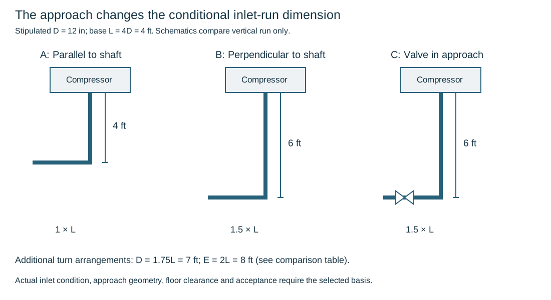
*Figure 5.4. Three schematic elevation sections within the five-configuration illustration: parallel, perpendicular and valve-containing. The dimensioned vertical sections show the stated 4-, 6- and 6-ft comparison; Table 5.3 retains the remaining turn-arrangement factors. This is a conditional layout comparison, not an inlet-flow qualification or fabrication drawing. [Structured data](assets/C05/c05-inlet-geometry.json).*
Keep the other inlet provisions on their own bases. A historical three-diameter power-test statement describes a different context from this stipulated four-diameter example. Neither supplies the selected machine's complete flow requirement. If wash water is injected to clean blades, the spray and gas mixing arrangement can require a longer straight section. One illustrated wash arrangement says that this could be 10 ft.
Its nozzle, injection duty and mixing requirements must be established with the machine and service, rather than inherited from a dry inlet.
A straightening vane is also an alternative with conditions. In the particular procedure, a tolerable vane complying with the applicable ASME or American Gas Association basis can permit dividing an illustrated arrangement's length by four. That is not a general permission to shorten any inlet, nor evidence that a vane cures an unsuitable valve, turn or wash-water arrangement. Establish whether the selected compressor and service permit the device and what qualified geometry and performance basis applies. Compare rerouting, elevation change and the evaluated vane arrangement as actual alternatives, carrying their loss, inspection, cleanliness and maintenance consequences.
This account also applies to strainer and break-out location. A permanent inlet strainer needs a clean-out arrangement. A temporary element needs its intended removal state. Flanges at a nearby valve can provide a natural break. An otherwise continuous line may require another removable connection to clear a casing or element.
The break must leave a supported assembly and preserve the required operating approach when restored. Removing a spool for maintenance cannot permanently consume the straight section that was part of inlet selection.
## Lubricating and seal systems are operating systems
A lubricating-oil system supplies clean oil at the required condition to bearings and associated equipment. A typical console includes a reservoir, primary and spare pumps, coolers, filters and controls. The arrangement also needs return paths, cooling and driving utilities, maintenance space and appropriate cleanliness. Its function is lost if any of those interfaces is treated merely as small-bore detail.
Gravity return can set console elevation and line routing. A high point, pocket or unsuitable return arrangement can interfere with drainage even when the supply pressure is adequate. Keep the oil reservoir, return route and machine connection elevations coordinated. In a cold environment, a selected reservoir heating arrangement adds another service and maintenance interface. A heating coil, cooler bundle or filter element needs its actual withdrawal space.
Primary and spare pumping arrangements should be understood in their operating and supply-loss states. The spare may have a different driver or startup mode, so power, steam or control availability can matter to its intended role. Describe what supplies the bearings during the transition rather than assume that two pumps automatically establish continuity. The specific control, reserve and acceptance requirements remain those of the selected installation.
Seal systems have another purpose and boundary. In an oil-sealed compressor arrangement, oil is supplied to the shaft-seal system under its specified pressure and temperature condition. Low-pressure returns and contaminated or sour-side oil can have different paths and treatment. Gravity and pressurized seal-oil arrangements need their own elevation, pumping and degassing interfaces. This treatment applies to the oil-sealed arrangements described here. It is not a statement that every compressor uses an oil seal.
A selected overhead seal-oil reservoir can preserve a limited supply when the pressure source is lost. Its static head, usable inventory and connection determine the reserve function. The manufacturer establishes the required arrangement and elevation for that machine. A historical elevation range is not sufficient to select the tank or establish its endurance. Level indication, access and maintenance also occupy space, and the reserve's limited duration should remain visible in the operating basis.
Auxiliary material and cleanliness requirements serve these functions. The selected oil system may require corrosion-resistant or otherwise controlled supply piping to avoid particles reaching critical equipment. The exact material and cleaning basis cannot be inferred from pipe diameter alone. [Materials](#chapter-c02), [utilities](#chapter-c12) and [cleaning and readiness](#chapter-c18) develop those selections and verification. This chapter connects them to the bearing, seal, reserve and return functions they must preserve.
### Reserve elevation for the actual oil return
Trace the gravity oil return from the equipment connection to the actual reservoir entry with its gradient, direction changes, sight-glass/manifold geometry and surrounding piping.
The reservoir's required volume and retention duty can affect its height. Raising it to resolve one clearance can consume the fall needed by the return. Raising the machine can restore that fall while changing foundations, platforms and maintenance access.
One particular return-layout detail distinguishes a minimum gradient of 1/4 in per ft from a planning gradient of 1/2 in per ft. These are separate criterion and layout inputs under that adopted detail. The historical reference to an API minimum is not a determination of the current edition's requirement for a project. For horizontal run length $\ell$ in feet and gradient $s$ in inches of fall per foot, required geometric fall is $f=s\ell$ in inches.
This relation accounts only for straight-run geometry. It does not demonstrate adequate gravity flow, reservoir entry conditions or clearance for fittings, insulation and tolerances. Evaluate actual oil flow, viscosity/temperature, venting and return arrangement on the applicable basis. Do not turn the larger planning number into an unrelated acceptance limit.
This elevation account makes a later change inspectable. A replacement console, raised reservoir entry, new pipe crossing or different machine support height can change the usable return. This can occur even if its pipe diameter remains the same. Reconcile the actual equipment and console boundaries. Preserve the gradient, datums and filled/cold/operating assumptions in the layout and handover record.
[Structured method data](assets/C05/c05-enrichment-methods.json). [Elevation and work envelopes](#chapter-c04) evaluates the surrounding space. The return must still deliver the lubrication system's operating function.
## Reciprocating compression introduces cyclic gas and mechanical behavior
A reciprocating compressor imposes cyclic gas flow. Single-/double-acting chambers, cylinders, stages and driver arrangement change the pulsation, foundation, access and piping interfaces. Average flow and final pressure do not describe the cyclic system.
Liquid carryover is a different problem from gas compression. A liquid slug can impose a severe mechanical demand because the cylinder is designed to compress gas. Suction separation and drains consequently have a protective role as well as a process role. A suction vessel or separator should deliver the required gas condition while collecting liquid. Its level observation, control and protective responses need to match the selected service and operating arrangements. A manually drained example should not be copied into a wet-gas service without evaluating the different accumulation rate and required response.
Interstage cooling can condense liquid, adding separation and drainage interfaces between compression stages. Some machine arrangements place coolers or connections directly over a cylinder and can differ from the common suction-from-top/discharge-from-bottom layout. Use the actual selected arrangement rather than turn one nozzle orientation into a universal rule. [Vessel and exchanger mechanisms](#chapter-c06) and [level measurement and control](#chapter-c22) develop the connected functions.
### A drain must discharge into a compatible pressure state
Interstage drainage is not complete when every low point has a drain symbol. A multistage compressor has connected regions at different pressures. Connecting a lower-pressure drain to a header maintained at a higher pressure can drive header liquid back toward the lower-pressure cylinder. The intended protective drain has then become a carryover path. A downward pipe route does not by itself overcome the pressure difference.
Compare the pressure at each drain connection with its receiving system in the relevant operating, startup, shutdown and isolation states. Include liquid head and the selected drain or control behavior, rather than compare only the normal stage pressure. A header connected to another running stage can remain pressurized while a stage or machine is idle. A shared header may therefore have a different pressure state from the machine whose drain is being considered. Establish what prevents reverse communication where a pressure difference can reverse the intended flow.
A generic check valve or steam trap is not automatically the appropriate solution for every liquid, gas and operating sequence.
A hypothetical equal-elevation example makes the pressure mechanism visible. Let a lower-stage connection be at 100 kPa gauge and a higher-stage connection at 500 kPa gauge. Let their proposed common drain header be at 300 kPa gauge. All use the same atmospheric reference.
Ignore liquid-head and line-loss contributions solely for this illustration, and assume a communicating open path. The higher stage has 200 kPa of pressure difference toward the header, while the header has 200 kPa toward the lower stage. This example shows possible direction. It supplies no flow rate, liquid inventory or adequate protective device.
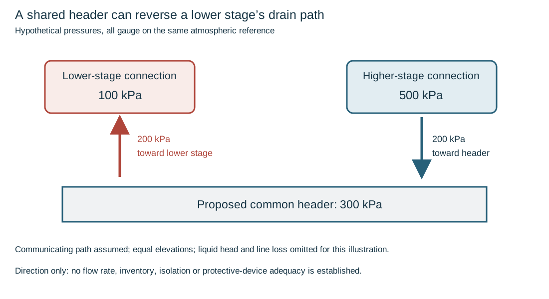
*Figure 5.5. Hypothetical pressure-state illustration, with gauge pressures on one atmospheric reference and equal elevation. The indicated reverse direction requires a communicating path. Actual isolation, controls, liquid head and losses are not evaluated. Under these assumptions, the 300-kPa header opposes discharge from the 100-kPa stage. Gravity fall alone does not establish forward drainage. [Structured data](assets/C05/c05-stage-drains.json).*
Process-liquid drains, stuffing-box leakage and distance-piece vents have different origins and destination requirements. Leakage collected between a compression cylinder and crankcase is not simply another interstage-liquid drain. A selected hazardous-gas service can use a gas-tight distance-piece arrangement and its defined vent or collection system. That example does not establish every compressor's seal construction.
Reconcile the actual machine and plant diagrams. Ensure leakage, gas release and process liquid reach their intended systems without an unexamined pressure connection. The operating and intervention procedure must preserve the isolation and restoration on which those functions depend.
Suction and discharge bottles and connected headers form part of the pulsating system. Temporary suction strainers can protect cylinders from solids during startup, but require a removable arrangement and a defined inspection/removal basis. Break-out flanges and lift access must leave the remaining piping and bottle supported. Neither a clean inlet nor a satisfactory pressure test proves that pulsation and structural response are acceptable.
Drivers add mechanical and utility requirements. A reciprocating engine can transmit vibration through its foundation and small auxiliary connections. Its fuel, intake, exhaust, cooling and lubrication arrangements need both their operating function and mechanical interfaces. A selected flexible connection may reduce transmitted motion but brings its own material, pressure, support and inspection requirements. [Components and flexible connections](#chapter-c03) and [operating inspection](#chapter-c19) provide the relevant boundaries. Generic hose is not a complete vibration solution.
## Pulsation, span and restraint must be evaluated together
Cyclic flow produces pressure pulsation, and the mechanical piping responds according to its mass, stiffness, geometry and supports. Copying a nonvibrating installation does not establish the response of another machine or route. The relevant machine data, acoustic and mechanical behavior and support conditions need their own evaluation. A thermal-flexibility arrangement can be dynamically unsuitable. Adding restraint for dynamic response can increase thermal or terminal loads.
A historical support-location method makes the necessary inputs visible. It first sets the route and identifies corners, intersections, elevation changes and concentrated masses. A supplier-dependent design natural-frequency input is then used with tables whose support boundary conditions are specified. Corners/intersections and straight runs are treated with different models. Finally, support positions are coordinated between adjacent lines and common piers. The method's usefulness is not a universal span number but its explicit connection between geometry, mass, boundary condition and the chosen dynamic criterion.
For a bounded educational lookup, consider the table basis for a cantilevered corner or intersection with a hold-down at one end. The NPS 3 row lists maximum schedule XX. Its tabulated frequency values are 202 cycles/s at a 2-ft span and 90 cycles/s at a 3-ft span. The associated example selects a table value nearest to, but not less than, 140 cycles/s. Under that particular lookup criterion, 2 ft passes the frequency comparison while 3 ft does not:
*Table 5.4. Bounded cantilever-frequency lookup.*
| Candidate cantilever span | Tabulated value | Comparison with the example's 140-cycles/s minimum |
|---|---:|---|
| 2 ft | 202 cycles/s | At or above the lookup criterion |
| 3 ft | 90 cycles/s | Below the lookup criterion |
This comparison does not establish a safe span for a new compressor installation. It retains the table's pipe/schedule and support model, and treats 140 cycles/s as the example input, not a general compressor speed or universal natural-frequency requirement. Other support boundary conditions use different tables. Actual gas pulsation, clamps, coupling moments, contents, thermal movement and the selected project/machine criteria are not supplied by this two-row comparison.
Hold-down hardware also has a defined behavior. A selected spring or resilient element can maintain contact while allowing a particular thermal movement. Over-tightening a resilient washer until it loses its intended resilience can defeat that function. A support under a warm discharge bottle may require a specific installation and operating adjustment sequence. Use the selected detail and supplier instructions. Do not merge a historical wedge-setting sequence with a different restraint system into a universal startup action.
### Turn local support decisions into a coordinated compressor layout
A reciprocating-compressor support layout develops through three related decisions. First locate the candidate weight and restraint points at corners, intersections, elevation changes and concentrated masses such as valves. Align neighboring lines with a common pier where practical, while retaining each line's own movement and load conditions. The candidate locations are not yet a completed spacing or dynamic design. Obtain the compressor supplier's selected design-frequency basis and the applicable pulsation/mechanical evaluation before using a frequency-based span lookup.
Resolve the evaluated hold-down location near the header, permitted cantilevers and remaining straight-run lengths.
A corner arm and a straight run have different boundary models. A hold-down limits uplift through its defined hardware stiffness and setting. It need not be an axial anchor or a fully fixed rotational end.
Resolve access around valves. Do not transfer an assumed restraint direction into the thermal model solely to improve a frequency estimate.
Finally work through the straight runs beginning with the smallest selected line, which can require the most support stations. Add intermediate rests and evaluate whether neighboring lines can share the underlying pier without forcing all their contacts or restraint stations to coincide. The selected layout procedure offsets intermediate supports rather than making every adjacent span equidistant. Its illustrated minimum offset is 3 in. That is a condition of that procedure, not a universal spacing cure.
A common pier can carry independent rests and hold-downs with different local positions and freedoms. Carry the summed static and dynamic reactions into its structural design.
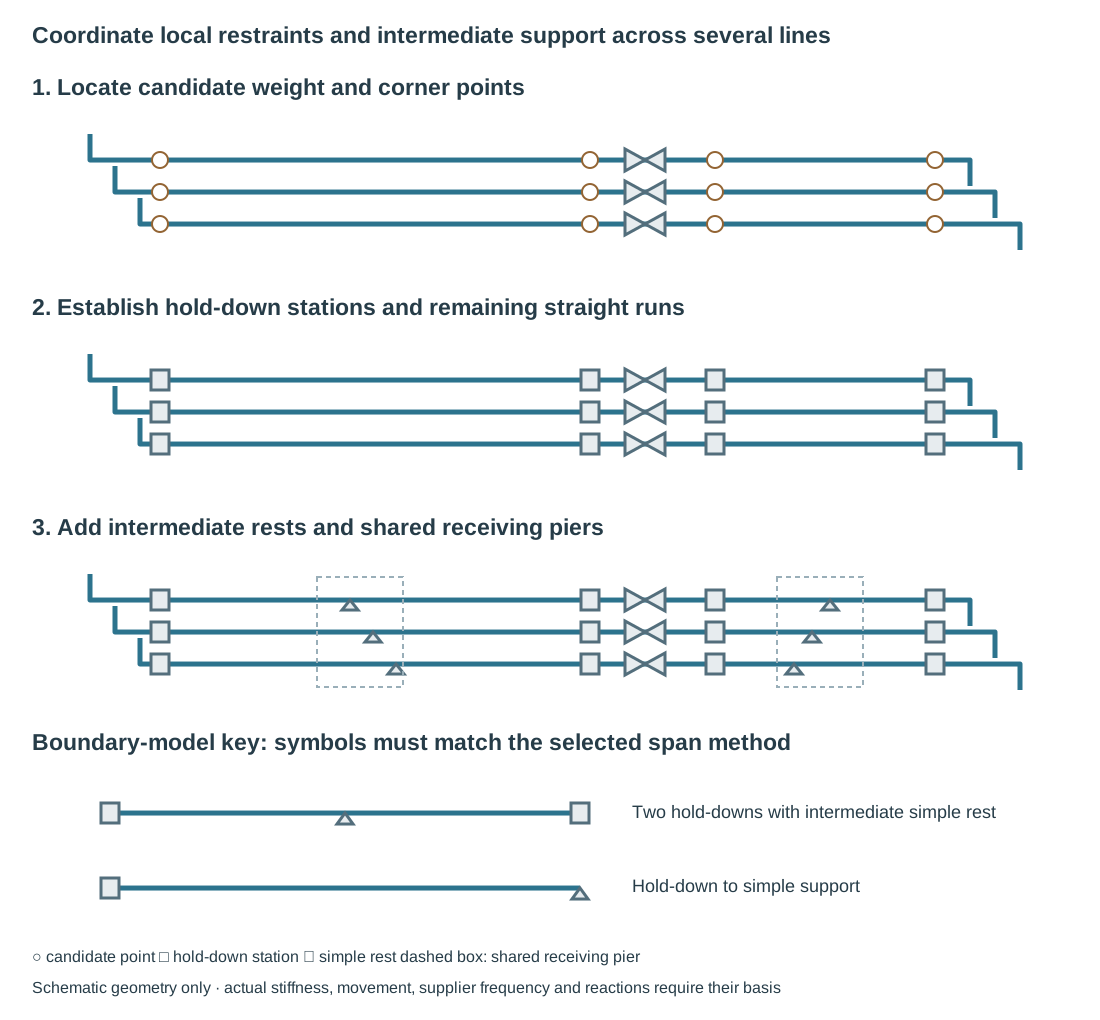
*Figure 5.6. An authored schematic sequence uses the same three lines through candidate local points, established hold-down stations and added intermediate rests on shared piers. No source spacing or design frequency is encoded. The boundary key distinguishes the selected two-hold-down/intermediate-rest model from one hold-down with a simple support. Their span symbols belong to their own methods. [Structured layout constraints](assets/C05/c05-support-layout-phases.json) retain those distinctions.*
The selected two-ended arrangement has hold-downs at both outer ends and an intermediate simple support. Its tabulated L is the subspan from that simple support to the right-hand hold-down. The entire interval between the outer hold-downs is not labeled L. The corresponding one-ended method addresses a hold-down-to-simple-support interval. Their tables are different.
The two-ended source sketch also marks the left subspan as at least 6 in shorter than L, a separate condition from the 3-in inter-line offset. Preserve that unequal-span convention if adopting that lookup. The schematic key supplies no lengths.
An intermediate rest changes weight contact and effective span while allowing the separately defined movements. Calling it a second hold-down would apply the wrong model.
Establish the actual contact and restraints before selecting any numerical row.
Damaged or blank cells are not zero or implied acceptance. The historical example's supplier frequency, table limits and drawn dimensions are not default values for another compressor installation.
Review the assembled layout with the actual thermal and operating response, rather than declaring the third panel complete by appearance. Changes to one pier can affect several lines. A dynamic restraint can oppose growth, and lift-off can remove an intermediate weight support. Check valve/bottle removal and test loads as well as normal service. Keep the support sequence tied to [span and weight modeling](#c10-spans) and [direction-specific frequency modeling](#c09-bent-offset-frequency). The qualified supplier and system analysis supply the actual acceptance basis.
### Preserve thermal freedom while setting the selected restraint
The illustrated metallic hold-down family restrains upward and downward movement while permitting sideways and lengthwise movement. It is therefore not a three-direction anchor simply because it appears rigid on a drawing. Its displayed temperature range is 40–650°F, and its application still needs the prescribed pipe, bearing and vibration basis. A different clamp or support criterion can assign different freedoms. Keep the actual detail in the mechanical model. Do not generalize one family's permitted lateral motion to a system requiring transverse restraint.
A resilient compression washer loses its intended function if installation flattens it permanently. One particular installation procedure begins with finger-tight nuts. It then uses a 45° wrench turn for 1½–3-in sizes and 90° for sizes 4 in and larger. Those turns are instructions for that selected detail and procedure, not general bolt torque values or a substitute for the required washer/load capability.
The smaller ¾- and 1-in variants also carry a specific stress-approval condition in the illustrated family. Set and verify the actual assembly under its governing instructions. Appearance or nut tightness alone does not prove the intended resilient reaction.
An adjustable spring wedge under a discharge bottle serves another state transition. The considered arrangement is installed with clearance and a loose spring before startup. After the connecting discharge leg warms and expands, it is adjusted to firm spring-loaded contact. Its position under the bottle's inlet and the independent cylinder support matter to that load path.
This is the selected wedge sequence. It must not be merged with spring-hanger release or generic clamp tightening into a universal warm-adjustment instruction. Keep capacity, permissible adjustment, startup condition and later empty or shutdown conditions with the device's identification.
Insulation changes the bearing envelope as well. The considered cold-insulated arrangements retain the insulation instead of cutting it back at the hold-down and use the specified cradle or load-transfer block. Insulation and cradle thickness change the required hardware fit. Ordinary bare-pipe size is not the completed outside bearing dimension.
Reassess the insulation's load-transfer and barrier duties, pipe movement and actual contact rather than close a clamp onto unqualified insulation. [Support details](#chapter-c10) and [Insulation interfaces](#chapter-c14) carry those material and thermal functions. The machine's vibration problem does not suspend them.
[Dynamic and mechanical analysis](#chapter-c09) and [supports and restraints](#chapter-c10) develop the quantitative evaluation and selected hardware. This chapter establishes why the reciprocating machine, bottles, route and operating states must be represented together. Operating vibration or an unexpected restraint condition is feedback into that basis, not proof that an arbitrary added clamp is the appropriate repair.
## Preserve function through installation and intervention
Before an installation is ready, the intended fluid paths, auxiliaries and mechanical configuration must exist. Check the selected equipment and nozzle identity, connection orientation, removal spaces, supports, restraints, auxiliary returns and utility interfaces. A certified outline can invalidate a preliminary envelope. A changed strainer, valve operator or seal system can alter space, pressure loss, weight or maintenance. Reconcile these changes with the evaluated arrangement rather than make the piping fit by undocumented field adjustment.
Startup and standby require their own checks. A temporary strainer, a closed exhaust valve, a blocked spring or an undrained steam inlet changes the state. Verify the configuration required by the selected commissioning and operating basis, including restoration after cleaning or testing. [Readiness](#chapter-c18) develops that verification. Pressure-test completion alone does not establish:
- A clean oil system;
- Steam at the turbine inlet free of damaging liquid condensate;
- A dynamically acceptable compressor route.
Maintenance should follow the physical disassembly path that layout reserved. A horizontally split compressor may need overhead piping removed before its cover is lifted. A vertically split machine needs its end withdrawal corridor. A pump, filter, cooler or seal reservoir has another removal task. Identify the remaining pipe/support configuration and the means of handling the component. An operating installation that is stable and aligned can become a different mechanical system as connections are opened or masses removed.
Changing service or hardware reopens affected decisions. A denser liquid changes head-pressure conversion and power demand. Another temperature changes vapor pressure and movement. A larger impeller or speed change affects machine performance and downstream conditions.
Replacing a valve or rerouting a branch can change loss, mass, thermal freedom and dynamic response. Trace these effects through the machine, connected equipment, protection, supports and operating states. Use [operating integrity](#chapter-c19), [repair and modification](#chapter-c20) and [engineering records](#chapter-c21) to preserve the actual configuration and reasons.
# Chapter 6 — Vessels, heaters, exchangers and storage
## The external arrangement must serve what happens inside
Internal collection, phase separation, heat-transfer and removal functions constrain external nozzles, elevations, supports and working space. Reconcile process vessel sketches, selected internals and vendor outlines before fixing the connections. A wrong level can defeat a takeoff, encourage flashing before measurement or obstruct withdrawal. [Plant arrangement](#chapter-c04) develops the surrounding space.
The same equipment changes state. A vessel may be empty during installation and filled in service. A reactor may be operating, regenerating or open for catalyst work. A heater may be carrying product or connected to temporary decoking services. An exchanger may be partly disconnected for bundle withdrawal. Preserve those configurations in the fluid, mechanical and access account rather than assume the running arrangement explains every task.
## Drums collect, separate and supply
Process drums can provide reflux collection, surge capacity, suction supply or general liquid collection. Horizontal and vertical arrangements place the inventory, vapor space and nozzles differently. Internals such as demisters, baffles, vortex breakers and distribution piping serve particular functions. They are not interchangeable fittings that can be moved to improve external routing without consequence.
A suction drum, for example, may separate liquid from gas before a compressor. The gas outlet and separation internals must deliver the required gas condition, while collected liquid needs observation, drainage and the selected control or protective response. A reflux drum connects condensation, liquid inventory and return to a tower. Its location and elevation affect both the connecting lines and the pump suction arrangement. [Rotating equipment](#chapter-c05) develops the inlet conditions of the connected machine, and [measurement and control](#chapter-c22) develops the level and flow functions.
Nozzle orientation should reflect the internal job and connected equipment. Locate liquid takeoff and pump-side piping to avoid unnecessary loss and a route that cannot meet suction conditions. Vapor outlets, drains, vents, level connections and manways need their corresponding level, phase and access. Where nozzles connect to internal distributors or baffles, the permitted external orientation is constrained by that internal arrangement. A proposed change should be coordinated with the equipment design rather than made solely from a piping plan.
Vendor-supplied steam drums and boiler-feedwater deaerators bring another package configuration. Steam generation and feedwater deaeration are functions different from ordinary reflux collection. Their selected steam/water, control and access arrangements must be coordinated with the supplied nozzles, internals and supports. A general drum sketch does not establish that package. Preserve the vendor scope and the connected utility requirements rather than independently relocate its functional connections.
Elevation brings several requirements together: liquid head, connected nozzle levels, clearance, maintenance access and common platforms. Horizontal drums often use saddles. Vertical drums may use skirts, legs or lugs according to their selected size and installation. Each arrangement transfers loads differently and leaves different spaces for piping and access. A nozzle inside a skirt or between piers needs room for its flange, insulation and removal task, not only a centerline position.
Drum piping must also accommodate equipment movement and the support of adjoining lines. A convenient shell or platform attachment is not automatically an adequate support point. Establish the actual attachment and reaction basis through [analysis](#chapter-c09) and [support and restraint decisions](#chapter-c10). Keep access to internals and manways available while arranging these supports. Opening the equipment or removing connected components creates another load and work state that the running configuration alone does not establish.
### Carry the internal drum arrangement into the nozzle and work plan
A horizontal drum example makes these interfaces concrete. The liquid outlet can be fitted with a vortex breaker, while a weir or baffle separates regions inside the vessel. The vortex breaker addresses the outlet flow. It does not make the surrounding liquid a quiet, representative sensing region. Level connections should communicate with the selected quiet region, away from outlet turbulence, and span the operating levels the function must observe. Moving them to shorten an external bridle can change what that assembly represents.
Coordinate the internal feature, actual low/high levels and communicating connections before fixing the outside instrument position.
A pressure connection in the vapor region and a temperature connection immersed in liquid can serve the selected vapor-pressure and liquid-temperature observations. Their phase and location define the information. Another measurement purpose can require another position. A hillside nozzle is a connection placed off the principal vessel axis to obtain a required elevation or access relationship. It can help arrange a level connection or manway, but its projection and opening still need the equipment design and an inspectable outside connection.
Translate the nozzle list into a connected arrangement. Trace the incoming stream, vapor outlet, liquid takeoff, vent, drain, steam-out and instrument paths independently. A steam-out connection and vent at opposite ends can serve a selected cleaning path. Their presence does not establish an isolation or vessel-entry procedure.
Confirm that the selected drain reaches the collecting region. Confirm that a platform or pier does not conceal the flange or valve that must be opened. Then compare the pump suction route with the available-head and flexibility requirements. A shorter connection can reduce loss while transferring more relative movement to the pump.
Support selection changes the realization. A platform carried by vessel trunnions follows a different attachment and movement path from one supported at concrete piers or from grade. Adjoining piping supported from the shell, platform steel or piers likewise sends reactions to different structures. Keep those reactions and relative movements in the equipment/support basis. Leg-supported vessel sketches intended for another service should not be transferred by size alone into a reciprocating-compressor circuit. Cyclic behavior is another selection condition.
Two additions can expose work that a simple drum outline omits. A boot attached below a horizontal vessel has its own lower connections and may require another platform for instrument access. The main drum platform can be perfectly usable while those lower tasks remain unreachable. A mixer requires an upward withdrawal path for its selected shaft and assembly. A removable floor section above it can preserve that path in a structure, provided its handling and reinstatement are defined. Neither the boot's small size nor the mixer's compact motor describes the complete work envelope.
For a sloping drum, declare its work point and slope, retain a horizontal platform, and specify whether nozzles and saddles remain vertical or follow another selected orientation.
Rotating a vessel outline does not automatically rotate every nozzle or support detail. If a nozzle is inclined to the required pipe run, calculate the resulting offset and connection geometry from the selected outline. This is a dimensional interface, separate from choosing the drum elevation for suction head or access.
## Tower internals govern nozzle and access choices
Tray/downcomer and packed-bed/distributor arrangements determine where feeds, reflux and draw-offs act and where personnel and parts can enter.
A downcomer is not merely a vertical obstruction. It routes liquid and contributes to the tray's liquid level and vapor-seal arrangement. Single-pass and multiple-pass trays occupy different internal regions, affecting manway orientation and the space available to enter and work. Bubble-cap, sieve and other tray configurations have their selected flow and support arrangements. Their exact dimensions come from the process and internals design. A historical tray table does not establish the dimensions of a new tower.
Packed beds need their selected supports and liquid distribution. A feed nozzle clear of external piping can still be poorly located relative to the distributor. Internal piping can extend the available nozzle orientation but adds parts, supports and maintenance. The purpose of the arrangement is useful distribution and access, not unrestricted freedom to put every nozzle on the easiest side.
Reflux is introduced at the selected upper location to distribute liquid over the contacting region. A baffle or internal distributor can be needed according to the inlet and tray arrangement. Side feeds and liquid draw-offs likewise have internal relationships. Reorienting a nozzle to shorten external piping can alter that distribution or create an internal pipe that is more costly to install, inspect and replace. Coordinate the alternative with the equipment and internals design, preserving the function before comparing the external route.
Temperature can vary along a tower. A bottom section and an upper section need not grow by the same rate when brought from installation to operation. Determine movement to each connected nozzle from the fixed or supported reference. Use the applicable temperature profile and material behavior, not one uniform temperature for the complete vessel. A nozzle near the top can accumulate movement from several lower sections.
[Thermal and mechanical analysis](#chapter-c09) develops the quantitative evaluation. This chapter establishes why the equipment profile and reference are required inputs.
Pump suction, access, low clearances, a reboiler and common platforms can impose different tower-elevation demands. If these are independent lower bounds on the same tangent-line point and datum, their maximum governs the least feasible elevation. Additional upper limits or coupled variables require a combined layout comparison. Changing a platform, pump or reboiler can change the bounds themselves.
A skirt-supported tower also needs skirt access, nozzle space and the correct foundation/support interfaces. Platforms and ladders should serve the selected operating and maintenance tasks. Tall-vessel guides, pipe supports and attachments must carry their evaluated loads while permitting intended relative movement. Keep manways, trays, packing removal and lifting paths available. The tower's external outline does not show all of the work its internals require.
### Locate the entry between the internals that occupy it
A tower manway needs a usable route into the vessel at its actual elevation. A nozzle clear of outside piping can still open directly against a downcomer hanging from the tray above. Read the tray arrangement in plan and section together. The plan identifies occupied circumferential regions. The section distinguishes the downcomer descending into the entry space from one beginning below its floor.
In the single-pass comparison, liquid traverses a tray toward an edge downcomer, then arrives at the next tray from the opposite edge. Successive downcomers oppose one another. In the two-pass comparison, center and side downcomers alternate. One level divides liquid from a center region toward two side regions. The next collects from both side regions toward the center.
These are different internal flow configurations, with different entry constraints. Their selected tray support, liquid-retention and vapor-contact construction remains part of the internals design.
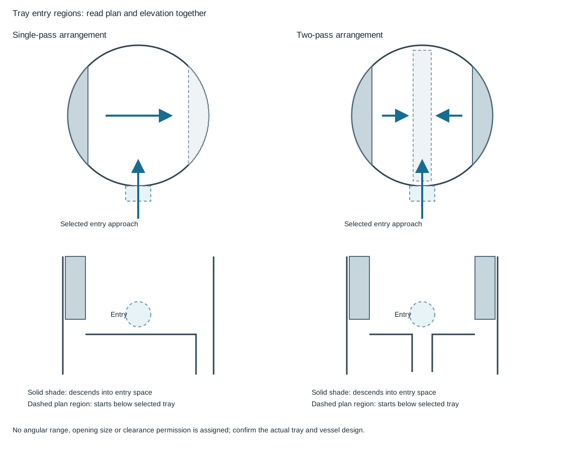
*Figure 6.1. The sections identify the downcomers descending from above and the passages beginning below the selected tray. The two-pass entry is shown at the level with side downcomers descending from above, leaving an approach between them. An incoming center downcomer at the alternate level would obstruct that central approach. Shading identifies physical regions rather than a universal allowed manway angle.* [Structured tray regions and entry constraints](assets/C06/tray-entry-regions.json).
For the illustrated two-pass construction, the useful entry levels are separated by an intervening tray because the incoming center downcomer obstructs the alternate level. The position between side downcomers still needs confirmation against the actual opening, tray supports and internal piping. In a single-pass arrangement, a wider circumferential choice can remain between the edge downcomer regions. This does not make every elevation or outside approach usable. Carry the intended personnel and component-removal paths through the complete shell opening.
Choose the manway level and platform together with the vessel and internals design. Moving an opening by one tray can change platform and ladder economy, while also changing the internals reached from that opening. The outside route from the tower maintenance side and cover handling belong to the same access task. So does passage of tray sections or other removable parts. Reconcile those tasks with [equipment spacing and access](#chapter-c04). Retain the actual opening and internals dimensions rather than adopt a generic clearance from a plan sketch.
### Preserve the delivery region when changing the external nozzle
Feed, reflux and draw-off connections have different internal duties. Reflux enters the selected upper contacting region and must be distributed over its tray. A feed can require delivery to a specified region or distributor on its own feed tray. A reboiler draw-off instead communicates with the selected liquid collection or sump region. Their common description as “process nozzles” does not make their internal endpoints interchangeable.
The selected single-pass reflux example below holds the internal delivery point fixed while comparing two external entry candidates. Candidate A enters near that point and turns down to the tray. Candidate B enters elsewhere on the shell and uses a longer internal route to reach the same delivery point. The outlet-side downcomer stays in its selected region in both comparisons. The candidates are alternatives for review. Drawing the internal pipe does not establish its capacity, support or acceptability.
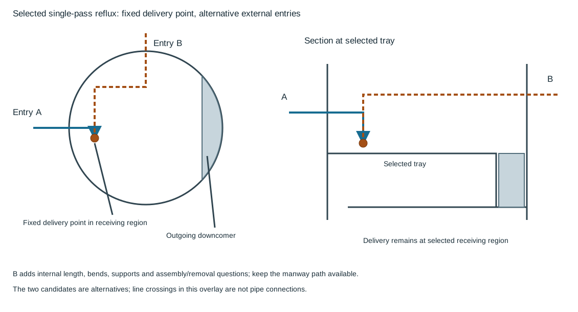
*Figure 6.2. The plan compares external entry A and candidate B against the same marked delivery point and downcomer region. The section locates the internal route above the tray and its delivery at the selected receiving region. The selected path needs its own elevation, supports, clearance and assembly/removal basis. Schematic line crossings do not imply connections.* [Structured endpoints and candidate routes](assets/C06/tray-delivery-candidates.json).
Internal bends and distributing pipes can extend the external orientation choices. They also introduce length, fittings, supports and joint or removal interfaces inside the tower. Keep the pipe out of the manway entry path and evaluate its relationship to tray sections and internal access openings. An internal flange can be proposed to permit tray removal or release a pipe that otherwise interferes with a tray manway. In that case, the reason and selected removable construction must remain explicit. An internal flange is not required merely because another vessel example has one.
The internal pipe also occupies process space. Liquid and foam above a tray can meet a horizontal pipe as an obstruction to their intended movement. A baffle or distributor can be needed to handle the selected inlet velocity and distribution duty. Those requirements must be evaluated with the tray and vessel design before a preferred external route is fixed. The least expensive outside nozzle location can add a more costly or less maintainable internal assembly.
Two-pass feed alternatives require their own consistent delivery arrangement. Two external nozzles can supply two internal receiving regions. A single external nozzle can instead supply a distributing arrangement serving both. The second choice does not simply reduce the nozzle count while leaving everything else unchanged. Its internal branches, elevations, support and removal paths have to be defined.
Preserve the center and side downcomer relationships for that chosen tray set. Do not transplant the single-pass reflux route into it without a new internals evaluation.
For a reboiler or side draw-off, identify the collecting region, liquid seal and takeoff endpoint independently. A nozzle communicating with a sump or downcomer collection has another function from a feed nozzle discharging over a contacting tray. The required elevation and internal outlet path follow that collection arrangement. Keep connection duty, internal delivery/collection point, tray level, external orientation and removable parts together at the vessel interface.
A changed nozzle or tray arrangement reopens those connected decisions.
## Reactors need process connections and a catalyst-work path
A reactor's bed, screens, inlet distribution, outlet collection and selected catalyst or inert materials constrain its flow path. Desulfurization, hydrotreating and related services can require different operating and regeneration connections.
The reactor may have fewer principal process connections than a fractionation tower, but their placement remains consequential. In the described vertical arrangements, process inlet and catalyst-loading access are associated with the top region. The outlet and unloading connection serve the lower region. A skirt, lug or ring-girder support changes how the outlet and unloading nozzle can clear the supporting structure. The selected reactor can use another arrangement. Use its actual process and vessel information rather than copy a typical nozzle orientation.
High-pressure shell thickness can alter external flange and clearance geometry. Insulation, nozzle projections and internal connections also affect the useful envelope. Confirm the selected construction before fixing nearby piping or a working platform. A nominal shell diameter is not necessarily the complete outside dimension around a nozzle or access cover.
Temperature and sample connections need positions that serve the process measurement while allowing operation and maintenance. These functions should be coordinated with piping and platforms, not left to an instrument detail after the reactor area is full. [Instrumentation](#chapter-c22) develops the sensing purpose and installation conditions, while [branches and connections](#chapter-c07) develops the physical connection mechanics.
### Several internal levels need not mean several shell openings
The mechanical arrangement of reactor temperature connections can use separate side-shell penetrations or a selected assembly entering from the top. These choices place the pressure-boundary openings and removable parts differently. Several points at different catalyst-bed elevations remain separate physical locations even when they share one entry assembly.
In the side-entry comparison, each selected connection carries an individual inserted component to its internal position. Its outside withdrawal corridor follows the component's insertion axis, which can be inclined. Adjacent piping, platforms and steel must leave room for the full removable part and its handling task. In the top-entry comparison, one long assembly extends down through a selected top opening to several internal elevations. Its release and extraction are primarily overhead, requiring the specified long withdrawal path above that opening.
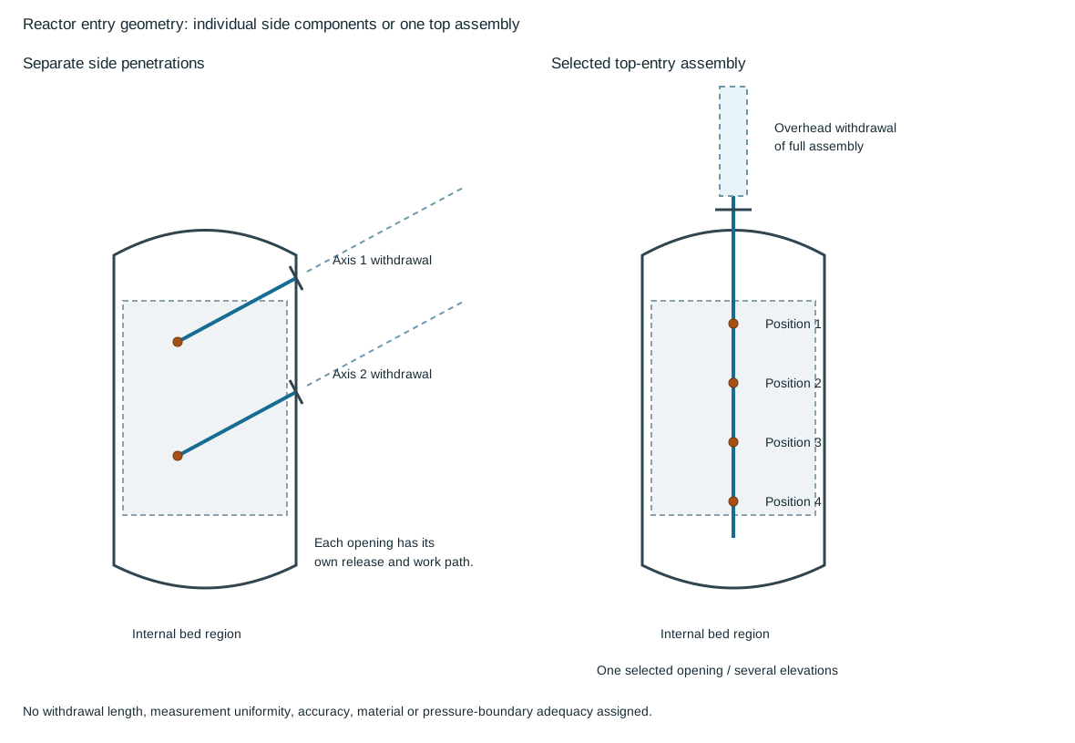
*Figure 6.3. The side-entry and top-entry outlines are independent alternatives. Point marks identify distinct internal elevations only. Dashed corridors follow the removable assemblies. They have no assigned lengths or minimum clearances. The top-entry example uses one selected opening for several internal positions.* [Structured penetrations, internal positions and withdrawal paths](assets/C06/reactor-entry-geometry.json).
| Mechanical choice | Internal and external relationships to retain |
|---|---|
| Separate side-shell connections | Each shell opening, inserted component, internal position and withdrawal axis; local release and handling space at each elevation |
| Top-entry assembly | Selected top nozzle or maintenance-access entry, internal assembly fit and positions, overhead release and full assembly withdrawal path |
Top entry can reduce the number of shell penetrations associated with the represented positions while increasing the length and overhead demands of the removable assembly. A side-entry arrangement distributes those tasks over the vessel elevations. Compare those consequences against shell thickness, insulation, actual nozzles, internal bed/support geometry, platform access and available lifting space. The assembly can enter through a maintenance access rather than a separate nozzle. Then its relationship to catalyst loading and opening that access must be resolved with the selected construction.
The mechanical comparison does not establish equally representative positions or uniform vessel temperature. Nor does it establish acceptable vibration or strength for a long assembly. The selected component materials and pressure-boundary design remain required interfaces. Keep this geometry with the [temperature connection basis](#chapter-c22) and actual equipment supplier information. Then reserve the verified removal envelope in the piping and platform arrangement.
Catalyst handling introduces a work path through the equipment. Top access, unloading routes, lifting or transport, temporary facilities and internal removal space belong in the arrangement. A loading connection integral with an inlet or manway can require that connection to be dismantled before work proceeds. Identify the remaining piping/support state and the place for removed items. The source-supported layout account does not establish a universal catalyst-loading or vessel-entry procedure. Those activities require the selected service, isolation, cleaning and work basis.
Regeneration and other special states can impose different temperatures, flow paths and internal or external conditions from normal production. Preserve the relevant interfaces when evaluating piping movement and access. The same principle applies to replacement of catalyst or internals: a change that affects distribution, pressure loss or temperature can reopen external piping assumptions. [Readiness](#chapter-c18), [operating integrity](#chapter-c19) and [intervention](#chapter-c20) carry the work into the applicable verification and return-to-service route.
## Heat exchangers contain two different flow arrangements
Keep each exchanger side's service, phase, pressure and temperature with its actual flow region and maintenance arrangement.
In a shell-and-tube exchanger, one fluid passes through tubes while another passes around their outside within the shell. Channel partitions can make several tube-side passes. Baffles direct shell-side flow and support the bundle. Pass configuration affects nozzle positions, pressure loss and the physical removal arrangement. A fixed-tubesheet construction, a removable bundle and a U-tube arrangement offer different access to the surfaces and components. The selected configuration determines what can be cleaned or withdrawn.
A TEMA configuration designation can identify the front-end, shell and rear-end arrangements before a detailed outline is available. It is useful for interpreting the equipment and its likely access needs. It does not establish a heat-transfer duty or current compliance. Use the adopted design basis and selected vendor configuration. Do not treat a historical service-class association as a universal selection rule.
### Trace the two sides before assigning a nozzle
A shell-and-tube section should be read as two separate contained flow paths. Follow each connection to the region it actually opens into. A channel nozzle opens into a tube-side compartment. A shell nozzle opens into the space around the tubes. The tubesheet and tube walls separate those regions. Their proximity in an outside view does not make the connections interchangeable.
Record the service, phase, pressure, temperature and material basis against the correct side before arranging the external piping.
In the two-tube-pass, one-shell-pass example below, the channel pass partition separates the inlet compartment from the outlet compartment. Fluid entering the upper compartment travels through one group of tubes and turns within the rear floating-head cover. It returns through the other group to the lower compartment. The partition prevents a direct inlet-to-outlet shortcut in the channel. The rear return space belongs to the tube side even though it lies within the outer shell-cover envelope.
A U-tube bundle provides another return arrangement: the tube bends themselves join the outward and return legs, and only one tubesheet is needed. These constructions perform a related flow operation with different parts and access tasks.

*Figure 6.4. The colored arrows explain the illustrated paths. Tube-side reversal occurs at the rear head. Shell-side flow crosses the outside of the tubes through successive baffle windows. The section is schematic and has no dimensional scale.* [Structured paths and components](assets/C06/exchanger-separated-paths.json).
The shell-side stream enters near one end and crosses the tube bundle through openings left by successive transverse baffles. It leaves near the other end. These cross-bundle turns still form one shell pass. A longitudinal baffle instead divides the shell along its length and can establish a two-pass shell route. A channel pass partition, a transverse shell baffle and a longitudinal shell baffle therefore need distinct names in a nozzle review. Their functions cannot be inferred simply by counting lines or arrows in a section.
The section also distinguishes the stationary tubesheet, floating tubesheet, floating-head cover and outer shell cover. Removing the channel cover gives a different access opening from removing the outer shell cover. Releasing a floating head is another operation again. Supports carry the shell, while the internal construction governs the bundle's movement and removal. Use this part-by-part account with the [withdrawal method](#c06-withdrawal-methods), rather than treating every end closure as a single interchangeable “head.”
### Read a configuration designation in three parts
Read a TEMA designation as front head, shell and rear-head/bundle-return construction, in that order.
It identifies physical arrangements that help frame piping and maintenance questions. Its historical set contains four front-head, six shell and seven rear-head entries. The adopted current standard and vendor design establish the applicable designation for a project.
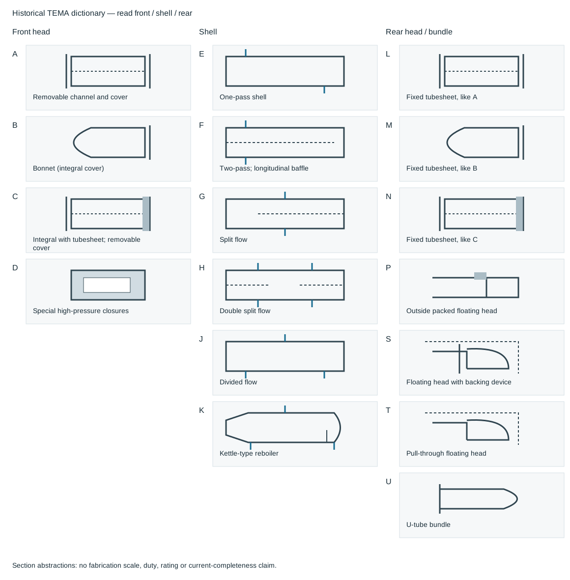
*Figure 6.5. Front-head, shell and rear-head alternatives are separate choices. The small sectional sketches emphasize the distinguishing construction, not fabrication dimensions or a complete assembled exchanger.* [Selectable letter records](assets/C06/tema-construction-dictionary.json).
| Position | Letter | Construction meaning |
|---|---|---|
| Front head | A | Removable channel and cover |
| Front head | B | Bonnet with integral cover |
| Front head | C | Integral with tubesheet, removable cover |
| Front head | D | Special high-pressure closures |
| Shell | E | One-pass shell |
| Shell | F | Two-pass shell with longitudinal baffle |
| Shell | G | Split flow |
| Shell | H | Double split flow |
| Shell | J | Divided flow |
| Shell | K | Kettle-type reboiler |
| Rear head | L | Fixed tubesheet, like A stationary head |
| Rear head | M | Fixed tubesheet, like B stationary head |
| Rear head | N | Fixed tubesheet, like C stationary head |
| Rear head | P | Outside packed floating head |
| Rear head | S | Floating head with backing device |
| Rear head | T | Pull-through floating head |
| Rear head | U | U-tube bundle |
Use the selected construction to establish cover/body release, connected-piping removal, shell-side cleaning and bundle withdrawal. The designation supplies neither pressure rating nor a certified removal sequence. A removable cover does not establish that the bundle can be pulled through that end.
**AES** decodes as an A removable channel and cover, E one-pass shell and S floating head with backing device. Its sectional example has a channel partition, stationary tubesheet, transverse baffles, floating tubesheet, floating-head cover and split ring inside the outer shell-cover arrangement. Front-cover access, rear-shell-cover access and release of the floating-head backing parts are different tasks. Identify their sequence and handling envelopes on the selected supplier information before arranging piping across either end.
**AKU** decodes as the same A front head, a K kettle shell and a U-tube bundle. Its illustrated tube-side return is formed by the U bends. It is not the AES floating-head assembly transplanted into a larger shell. The kettle section includes an enlarged shell region and a weir beyond the bundle. Those internal liquid and vapor regions have consequences for shell connections, as developed in the [kettle region account](#c06-kettle-region).
The designation does not give the operating liquid level, duty, material, design pressure or nozzle schedule. Check those items against the selected equipment and process basis.
### Compare nozzle alternatives within the same internal arrangement
The nozzle patterns below show why changing an external connection begins with the internal flow regions. The one-pass shell examples place shell nozzles at different ends of the bundle region. The two-pass shell examples place them near the same end on opposite sides of the longitudinal division. Split-flow and double-split-flow sections introduce different divisions and connection patterns.
The repeated one-pass patterns (alternatives 1 and 5) and two-pass patterns (alternatives 2 and 6) retain the same nozzle geometry. Their rear shell closures differ. Alternatives 1 and 2 show a flanged rear closure. Alternatives 5 and 6 show an unflanged closure.
The nozzle pattern alone therefore does not establish rear-cover access. A kettle shell and a shell with a far-end tube-side connection add further alternatives. These are configuration examples, each read on its own. Their features must not be combined into an unexamined new arrangement.

*Figure 6.6. Eight section patterns retain the distinct source alternatives. They include the flanged rear closures of alternatives 1 and 2 and unflanged rear closures of alternatives 5 and 6. Blue ports belong to the shell. Orange ports belong to the tube-side end compartments. Port marks show connection locations, not service direction, nozzle size, angular orientation or engineering permission.* [Structured alternatives](assets/C06/exchanger-nozzle-alternatives.json).
A proposed relocation must preserve the connection's side and intended region, the pass division and return path, and the required phase behavior. Review the changed arrangement with the exchanger design, then update the nozzle schedule and outline together. Moving a shell connection across a longitudinal division or putting a tube-side connection into another channel compartment can change the route through the equipment. A shorter external pipe does not establish equivalent internal behavior.
Retain nozzle facing/projection, foundation/saddle clearance, cover/bolt access, bundle handling/insulation, equipment movement and attachment loads.
The drawings provide no nozzle dimensions, thermal duty or pressure-loss curves. Their useful result is construction questions and distinct alternatives to take to the equipment interface. The actual material, pressure, temperature and operating-state requirements carry forward into the [vendor-outline review](#c06-exchanger-connections).
A double-pipe or hairpin arrangement puts one flow path inside another. Fins can increase the heat-transfer surface, and modules can be connected in arrangements suited to the duty and pressure service. The small-diameter form can be useful where a large shell is unattractive, but the connection and withdrawal geometry still matter. A hairpin must have its specified removal path. Shortening external piping across that path can defeat the modular maintenance advantage.
Plate exchangers direct hot and cold fluids through alternating channels in a plate pack. The plate and gasket pattern forms the distribution and pressure boundary, while the carrying bars, covers and compression arrangement hold the pack. Access can involve releasing and opening the pack rather than withdrawing a long tube bundle. Gasket/material and operating limits remain those of the selected construction. The compact form alone does not establish suitability for a pressure, temperature or fluid.
A spiral exchanger forms continuous passages from a wrapped plate arrangement, with its selected covers and nozzles. Its access and support differ from a shell-and-tube unit. Compare those differences against the service, cleaning and maintenance task. Do not select every exchanger on surface area or plot-space savings alone. Compact equipment can save space without eliminating the need to reach and service its actual internal parts.
## The vendor outline is a functional interface
Nozzle side, orientation, elevation, facing and projection influence the external route. They also remain constrained by internal flow, construction and maintenance. A proposed nozzle change can reduce an unnecessary loop or improve a stacked arrangement, but it should be reviewed with the equipment design. The piping layout does not have independent authority to move an internal flow connection.
Locate related exchangers to serve the process and the required removal path. A channel cover, shell cover, bundle or hairpin can need a different withdrawal direction and lifting position. Fixed handling devices, trolley or crane arrangements and mobile extractors are alternatives whose usefulness depends on the actual equipment and job. A route clear of the running equipment can obstruct a cover or bundle as soon as it is moved.
Removal dimensions must be established for the selected equipment. An uncertain catalog dimension or incomplete preliminary outline should remain an unresolved interface until clarified, while alternative layouts can be studied around a declared envelope. Do not infer a missing dimension from the neighboring catalog row or assume a larger-looking drawing provides a certified clearance.
Exchanger supports and thermal behavior also matter. The selected equipment can need movement between its support points and coordinated freedom in the attached piping. Stacked units can simplify a process connection but add support, nozzle and maintenance demands. Include equipment displacement and attachment reactions in [analysis](#chapter-c09) and [support design](#chapter-c10), and preserve the physical clearances through installation.
Pressure, material and connection differences across equipment and field piping need their actual design basis. A nozzle rating is not an external-load allowable. A matching flange size is not proof that the bore transition, material or inspection requirement is satisfied. [Materials](#chapter-c02), [joints](#chapter-c03), [pressure design](#chapter-c08) and [fabrication quality](#chapter-c16) develop those requirements. This chapter keeps them connected to the actual flow side and equipment configuration.
### Select the withdrawal method before reserving the corridor
The channel, bonnet, shell cover and bundle are different removable parts. For a horizontal exchanger, locate the bundle end toward the selected maintenance approach and retain bonnet or cover handling on its own side. An operating line that fits beside the shell can still block a flange bolt, davit sweep or bundle as it leaves the equipment. Paired and grouped arrangements should therefore be checked at the channel/flange envelope as well as the shell section. Controls can occupy useful side space when their work position and removal path remain clear. Compact pairing does not make that side space unlimited.
The selected pulling and carrying equipment determines how much of the outside corridor is used. One pulling-post arrangement locates its post at twice the bundle length from the illustrated exchanger end. A trolley-beam arrangement instead reserves a travel dimension of bundle length plus a nominal 2 ft, paired with 610 mm, in its illustrated structure. These are different geometries and methods, not two interchangeable rules for the same free space. Identify the dimension's endpoints, the bundle length and the equipment travel before using either as a planning basis. The actual supplier, rigging and handling arrangement establishes the final envelope.
*Table 6.1. Different internal-access tasks create different outside paths.*
| Selected form and method | Consequential path or interface |
|---|---|
| Horizontal removable bundle with fixed pulling and carrying equipment | Axial extraction, supporting/holding positions, trolley or gantry travel, then lowering and transfer |
| Horizontal bundle with a mobile extractor and crane | Extractor approach and shell-flange clamp, reaction path, crane balance and lift, then grade/vehicle transfer |
| Vertical removable bundle | Upward extraction and overhead lift; lower cover handling can be another task |
| Spiral exchanger | Cover-plate swing plus any intentionally removable connected spool |
| Plate exchanger | Opening the pack and withdrawing individual plates within the selected carrying-bar arrangement |
| Air cooler requiring major section removal | Crane approach and section lift, with header, motor and minor-servicing access retained separately |
A hydraulic extractor offers a useful load-path example. It clamps at the exchanger shell flange. Its hydraulic pulling system acts against the selected reaction arrangement while the crane and leveling system carry and balance the extractor and withdrawn bundle. The load and center of gravity change as extraction proceeds. A crane that can reach the initial position and a clear axial corridor answer only parts of the task.
Equipment weight, pulling reactions, flange/structure capacity, holding arrangement and final transfer must be evaluated together. A catalog or historical description of one extractor's weight or force is not the rating of the tool brought to the site.
A fixed trolley or traveling gantry adds permanent steel, rails, pulling points and maintenance. Mobile handling can avoid some permanent structure while requiring a useful approach, setup and lift path for the actual machine. Compare the selected work frequency, part size/weight, operating neighbors and access before assigning an economic preference. Stab-in reboiler withdrawal can require a removable handrail section at its outward path. Define the temporary protection and reinstatement rather than assume that missing railing is a complete access solution.
Nozzle alternatives should be studied with this withdrawal plan. A changed shell nozzle can simplify an external route, while the pass construction limits where it can act. A gooseneck or elbow nozzle can reduce spacing between stacked exchangers by turning the connection within a shorter vertical envelope. It changes the equipment connection and must be accepted with its internal flow, fabrication and load basis. For an air-cooled condenser, a single-pass far-end outlet and a double-pass same-end outlet can produce very different gravity-return lengths and elevations. Reorienting the cooler or changing its passes can simplify the external path, but those alternatives also change the thermal and equipment configuration.
Material and movement can reverse a visually compact choice. Avoid making a large alloy route acquire an unnecessary offset solely to accommodate a smaller carbon-steel line when moving the smaller connection provides a workable alternative. A loop between hot feed exchangers and a selected moving support at one exchanger are distinct ways of accommodating a defined relative movement. The moving support changes equipment reactions and alignment as well as pipe geometry. It is not a generic substitute for flexibility. Evaluate the actual supported equipment, displacement and terminal limits through [analysis](#chapter-c09) and [supports](#chapter-c10).
### The supplied release joint determines what must move
A hairpin's external connection and its internal withdrawal route need separate inspection. In one supplied arrangement, a compression/disconnect assembly allows tube release and withdrawal from the return-housing end. The connected field manifolding remains in place. The shell and tube connections, seal rings, split rings, compression flanges, end covers and tube-return connector are parts of that particular release arrangement. A conventional sketch that assumes every external flange must be disconnected can introduce unnecessary breakout joints while still leaving the real withdrawal end obstructed.
Use the selected assembly drawing to identify pressure-boundary parts, the release joint and withdrawal end.
Trace the released part through its complete axial travel, supporting and lifting positions, and final transfer. Check the tooling and hand access at the release parts as well as the long extraction space. The release mechanism can reduce dismantling of field piping. It does not remove isolation, draining, support, handling or reassembly work. Do not infer the release sequence or reusable seal condition from the name hairpin.
Compare two installation candidates using that actual mechanism. A manifold retained at the connection end can simplify intervention if the supplied release design permits it. A removable field spool can instead provide access where the selected unit or neighboring arrangement requires it. Additional flanges introduce pressure-boundary joints and maintenance work, while fewer flanges can make an otherwise necessary intervention impractical.
Decide from the actual release and handling path, connection integrity and service conditions. The equipment procedure establishes the permissible disassembly and reassembly actions. The layout preserves the space and load path needed to perform them.
### A maintenance connection can carry a different load path
Consider a particular tower-supported vertical reboiler arrangement that does not require springs. Its selected detail leaves the reboiler lug above platform support steel in the initial connected configuration. Before the supporting connection is opened for channel and bundle work, a shim engages the platform load path. The platform then carries the remaining reboiler during the specified maintenance state. Unbolting the nozzle and channel connection before establishing that path would change what holds the assembly.
Figure 6.7 isolates the relationship. The illustrated detail uses a nominal 1-in gap, paired with 25 mm. That is the particular example dimension, not a clearance to adopt for other equipment. Adding the shim changes contact and reaction, so it changes the mechanical system even while the equipment remains at almost the same drawn position. The selected platform, lug and supporting structure must be able to carry the relevant load and preserve stability before the connection is separated.
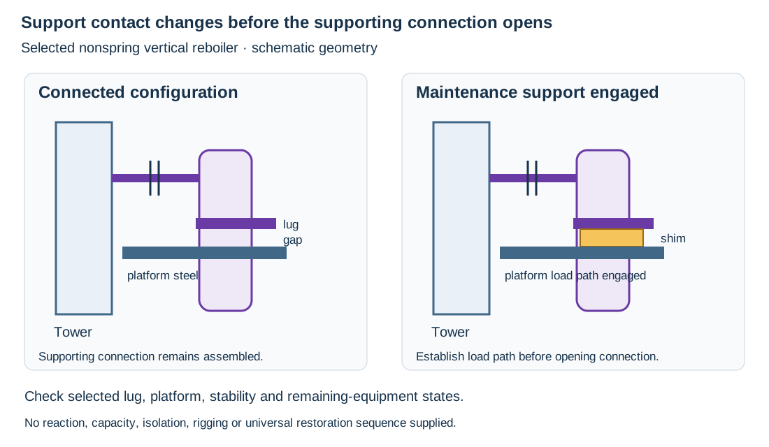
*Figure 6.7. A bounded nonspring tower-supported reboiler example. A gap separates the lug from platform steel in the connected configuration. A shim engages that support before the supporting connection is opened. No reaction magnitude, structural capacity or execution approval is supplied. [Structured states](assets/C06/reboiler-load-handoff.json).*
A spring-supported reboiler and an independently supported vertical exchanger have different operating and maintenance premises. Do not transfer the shim detail merely because the vessels are vertical. Follow the actual connection and support arrangement. Include what remains after channel removal and what the lifting system carries during bundle extraction. The removal drawing needs those states as well as the free space above and below.
Return to service requires the intended operating configuration to be restored under the selected work basis. This example explains a maintenance load handoff. It supplies no universal shim-removal or spring-setting sequence. Verify the actual support contacts, connection restoration and movement freedom specified for the installation. A retained temporary support can alter operating loads even if the pressure boundary has been successfully reassembled.
### Footing thrust and nozzle acceptance are separate comparisons
A horizontal exchanger transfers connected-pipe effects through its nozzles and shell to the supporting footings. A historical preliminary footing screen makes one part of that account explicit. Under that adopted method, thrust exceeding 30% of the exchanger weight carried by the particular footing triggers detailed stress analysis. Let $w$ be total exchanger weight as a force, and let $\alpha_c$ and $\alpha_s$ be the fractions carried by the channel and shell footings. The screen values are
$$
F_{c,\mathrm{screen}}=0.30\alpha_c w,
\qquad
F_{s,\mathrm{screen}}=0.30\alpha_s w.
$$
Fractions are dimensionless. Screen thrust and weight use the same force unit. The method's normal-distribution assumption is $\alpha_c=0.60$ and $\alpha_s=0.40$, giving $0.18w$ and $0.12w$.
These are checked proportions under a stated preliminary basis, not verified footing loads or equipment acceptance limits. The actual distribution, thrust direction, relevant state and load combinations must agree with the adopted comparison.
The coefficient 0.30 is not an actual contact-friction coefficient. A sliding footing's contact material, normal reaction and restraint determine its frictional behavior. A nozzle force-and-moment or material-stress check is another evaluation again. Passing a footing screen does not establish nozzle acceptability. A low-friction slide detail may reduce particular transferred forces but needs its own contact, movement and foundation evaluation. It does not guarantee a remedy or reconcile an incompatible analysis assumption by choosing the apparently stricter number.
[Structured screen method](assets/C06/footing-thrust-screen.json) preserves the quantities and scope.
## Reboiling and condensation make head and phase central
A reboiler supplies heat that produces vapor for the connected process. A condenser removes heat and changes the returning phase. Their elevation and piping influence circulation and phase handling, so the connection cannot be developed solely from the shortest plan route.
A thermosiphon arrangement relies on a density difference to provide circulating head. The difference is between column liquid and the vapor-liquid mixture in the reboiler path. Piping resistance consumes part of that available head. Keep the loop's geometry, liquid levels, mixture conditions and pressure losses associated with the selected reboiler and operating state. Adding an elevation, long route or restrictive component can change circulation even if the heat-transfer equipment itself is unchanged.
Horizontal and vertical arrangements put the flow paths and supports differently. A horizontal thermosiphon unit can be located near grade with a short connection to the column. In the described vertical arrangement, liquid enters below and a vapor-containing stream leaves above. The unit can be supported from the tower or from a separate structure according to the selected equipment. The tower's ability to carry the reboiler and its attachment reactions must be established. A convenient lug location or nearby platform is not proof of capacity.
A kettle arrangement contains a boiling region with its selected level and withdrawal arrangement. Its relationship to the tower liquid level differs from a simple external once-through route. A pump-through or fired reboiling arrangement adds another source of flow/head and equipment interfaces. Use the selected process configuration to decide which elevation and circulation constraints apply. The name reboiler does not define them all.
A bounded historical screening method for vertical thermosiphon connections relates inside diameter to duty:
$$
\frac{D_{\mathrm{in}}^2}{q}=12\ \text{to}\ 15,
\qquad
\frac{D_{\mathrm{out}}^2}{q}=25\ \text{to}\ 30,
$$
with diameter $D$ in inches and duty $q$ in MMBtu/h. These numerical ranges have that unit convention. They are not dimensionless physical constants.
This screen is not a selected nominal pipe size, a hydraulic calculation or a complete design result. It supplies neither fluid-property validity bounds nor a demonstrated circulation margin for a particular installation. Actual inside diameter depends on the selected pipe and wall. The route must still be evaluated against available head, phase behavior and equipment requirements. The preliminary diameter/duty relationship needs an explicit scope and connection to the physical evaluation. It is not approval.
### A level connection must communicate with the region being controlled
A kettle can contain a boiling region upstream of a weir and a collecting region downstream. The weir controls the spillover relationship between them, but it does not make their instantaneous levels identical. A connection that physically fits the shell can therefore communicate with the wrong liquid region for its intended measurement or control action.
Consider a controller intended to regulate withdrawal from the collecting region. If its liquid-level connections are placed before the weir, the observed head belongs to the boiling region. Changes in downstream collection or withdrawal can then remain unseen or be interpreted through the wrong relationship. Moving a nozzle on the outline is consequently a process and equipment decision. Identify the controlled inventory, weir, liquid withdrawal and sensing connections together on the P&ID and equipment section. A nozzle tag or an attractive pipe route cannot establish that internal communication.
The required connection elevations and measuring span depend on the selected level range and sensing method. This example supplies no universal weir height or half-height setting. Verify the actual internal geometry and the instrument's pressure path, fluid density and operating states through [measurement and control](#chapter-c22). Preserve separate boiling-side and collecting-side functions when checking the supplier outline. A level tap beside the wrong region is not corrected by calibrating its label to the intended one.
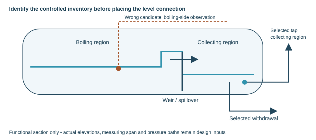
*Figure 6.8. A functional kettle section separates boiling inventory from collected liquid beyond the weir. The selected collecting-level connection must communicate with that region. The dashed candidate before the weir observes a different inventory. No dimensions, operating levels or acceptance result are assigned. [Structured regions and connections](assets/C06/kettle-region.json).*
## Put measurement and distribution where the phase permits them
Liquid near its boiling condition can flash when pressure falls. An elevation rise or resistance before a measurement or control device can therefore change the phase entering it. A device and calibration intended for liquid service should not be assumed to retain the same function when the incoming flow becomes two-phase.
Consider a liquid draw-off whose route rises before its meter and control valve. The route can use available liquid head and introduce loss before those functions. An alternative can keep the measuring/control section at a lower elevation and place the later rise downstream, or cool the stream before the selected measurement. Evaluate the actual pressure, temperature and losses. Lower elevation can provide head, but a geometric sketch alone does not prove that flashing is prevented under every condition. [Measurement and control](#chapter-c22) develops the device-specific basis.
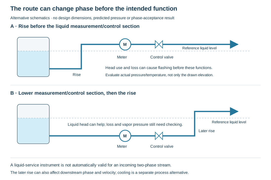
*Figure 6.9. Two alternative function-only routes from liquid near its boiling condition. The first rises before the selected liquid meter/control section. The second places that section below the reference liquid level before a later rise. Actual head, loss and vapor pressure still need evaluation. Neither schematic predicts pressure or declares phase adequacy. [Structured flow paths](assets/C06/equilibrium-paths.json).*
Distribution to parallel equipment is another phase-sensitive function. Liquid momentum and vapor resistance preference can send different mixtures through apparently similar branches. Equal total quantities or equal pipe sizes do not establish equal vapor/liquid fractions. Develop the incoming approach, splits and branch paths for the required distribution. Carry the actual pressure-loss and phase conditions into evaluation.
Hydraulic balance is the objective. Geometric symmetry is one means of pursuing it under a selected basis. For heater and exchanger distribution, an adopted practice may require particular symmetry and approach geometry. Another basis can permit a different geometry where outlet hydraulic balance is established. Do not silently substitute one rule for the other. Preserve the selected inlet and outlet requirements and evaluate the participating phases rather than choose a universal sketch.
Flow-regulating valves can adjust branch resistance or serve a selected isolation function. They do not automatically distribute liquid and vapor correctly at an upstream junction. An outlet temperature can help an operating comparison for matched cells and conditions. It is not by itself proof of equal flow under unequal duties or phases. Coordinate the distribution method, measurement and operating adjustments with the equipment's actual service.
## Air cooling adds airflow, drainage and cell movement
An air cooler passes the process fluid through tubes while air flows around an extended surface. Fans move the air. In a forced-draft arrangement they are below the tube cells. In an induced-draft arrangement they are above. The selected fan, tube and frame configuration determines access and the space around the cooler, as well as the cooling function.
A cell is a set of tubes and connections with its specified passes. An even-pass arrangement can put inlet and outlet at the same end. An odd-pass arrangement can place them at opposite ends. The nozzle positions therefore affect the return route and equipment elevation. Reorienting a cell or changing the pass arrangement can improve piping but also changes the selected thermal and equipment configuration, so it requires coordinated evaluation.
Condensing service needs a path for the formed liquid. An overhead-vapor line can begin condensing before it reaches the cooler. A pocket can retain liquid and deliver a slug to the equipment rather than a controlled incoming mixture. Keep the selected inlet and outlet drainage paths associated with tower, cooler and accumulator elevations. Evaluate path behavior in operation and shutdown. A rack-mounted cooler can suit those relationships while adding structural, lifting and access interfaces.
Multiple cells require distribution appropriate to the number of connections, phases and duties. Center-fed or staged headers and selected regulating arrangements are alternatives, not one rule for every number of cells. Inlet and outlet fluid conditions can differ substantially when condensation is extensive. Do not impose identical manifolding merely because the equipment has matching rows of nozzles. Do not remove a selected symmetry requirement merely because another service did not need it.
Inlet piping can be hotter than the outlet piping, creating differential movement. The cells and frame have their permitted movements and restraints. Attached headers and supports must be evaluated with them. A common frame does not make every nozzle a fixed point or guarantee that opposite headers grow together. Compare normal, startup and relevant partial-service conditions through [analysis](#chapter-c09) and [supports](#chapter-c10).
Humidified or other water-assisted cooler forms add water inventory, circulation and weight. Their elevation, foundation and drainage demands differ from a dry rack-mounted unit. Fan access, tube servicing, header plugs and major section removal also require actual work paths. [Layout and access](#chapter-c04) supplies the common spatial method, while this equipment account supplies the nozzle, drainage and maintenance mechanisms that method must preserve.
### The approach to a junction can separate the phases
Parallel exchangers require the intended liquid and vapor delivery to each participating unit, as well as an acceptable total flow. At a two-phase junction, those are different questions. Liquid momentum can favor a continuation of the incoming route while vapor responds differently to the branch resistances. Similar branch diameters do not establish comparable phase fractions, and similar total flows do not establish comparable heat-transfer conditions.
The paired geometry below compares two approaches. One continues toward exchanger B with a side route toward A. The other meets the branch midway between the exchangers. In the first construction, the two outlets do not present the same approach to the incoming mixture. In this example with exchangers intended for matching duty and pressure drop, liquid favors B and vapor favors A. That is the mechanism being illustrated, not a prediction of the actual fractions at an unspecified junction.
In the second construction, the incoming stream meets opposed branch routes with comparable geometry.
This removes the illustrated straight-through preference and supplies a basis for evaluating distribution.
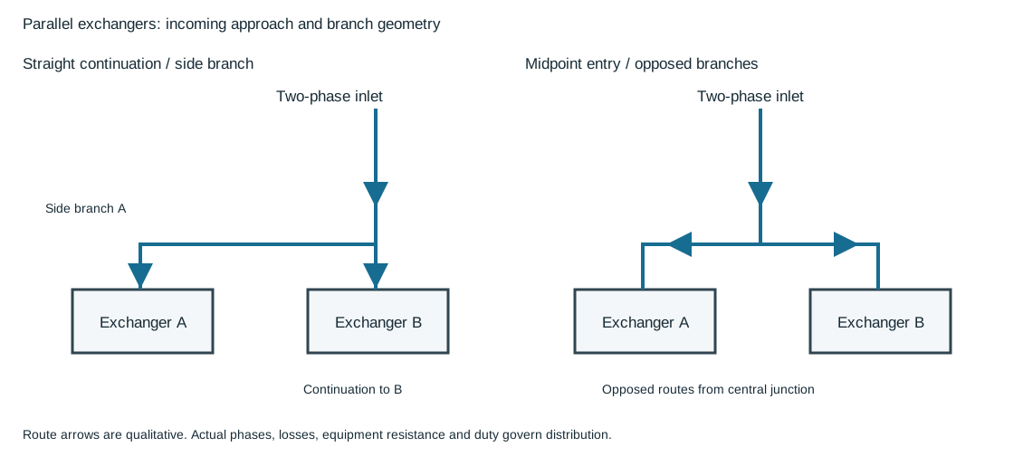
*Figure 6.10. The first route gives B a continuation of the inlet approach and A a side branch. The second enters midway between A and B and divides into opposed routes. Arrows show routes only. Their thickness and spacing carry no quantities. No equal-flow or equal-phase guarantee is assigned.* [Structured junction alternatives](assets/C06/two-phase-exchanger-junctions.json).
Evaluate the comparison with actual inlet pressure/temperature/phase, approach direction, branch elevations/losses, equipment duties/resistance and required distribution range.
A phase change along one route, different exchanger resistance or a changed operating combination can invalidate a comparison based only on matching outside pipework. Carry those conditions with the [phase-path account](#c06-phase-paths) and [fluid-state description](#chapter-c01).
### Header layout makes the distribution alternatives visible
An air-cooler manifold connects a row of process nozzles through common inlet and outlet headers. The inlet row and outlet row serve different states when substantial condensation occurs in the tubes. Their similar appearance does not establish that the same symmetry requirement applies to both. An inlet carrying vapor and liquid requires a distribution account for those phases. An extensively condensed outlet requires its own collection, pressure-loss and drainage account. Retain the supplier's passes and connection locations while evaluating both.
Three historical plan arrangements make the header choices concrete. The first feeds one end of the inlet header and collects from the opposite end of the outlet header. The second enters the inlet header at its center and takes the outlet from the center of the corresponding collecting header. The third divides the incoming line between two separately center-fed header groups, then combines the group outlets. These are alternatives for process-fluid distribution and collection. The diagrams do not add an auxiliary circuit or an operating-control arrangement.
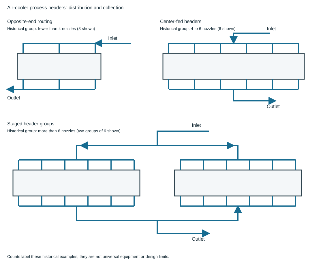
*Figure 6.11. The historical grouping labels are fewer than 4 nozzles, 4 to 6 nozzles, and more than 6 nozzles, counted along each process-nozzle row. The illustrated rows show 3, 6 and two groups of 6 respectively. Those counts define these examples rather than universal design limits. Arrows identify inlet distribution and outlet collection. No flow quantities are encoded.* [Structured manifolds and nozzle groups](assets/C06/air-cooler-process-manifolds.json).
| Arrangement in the comparison | Connection relationship to inspect |
|---|---|
| Opposite-end feed and return, illustrated with three nozzles per row | The inlet approaches from one end; the collected outlet leaves from the other. Follow each complete equipment path rather than comparing inlet branch lengths alone. |
| Center-fed headers, illustrated with six nozzles per row | The center connection divides toward both ends of the inlet row, while the outlet branches collect toward a central connection. Check the two halves and the individual branches. |
| Staged groups, illustrated with two groups of six nozzles per row | The first split feeds each group header; each group distributes again. The outlet groups collect locally and combine at a further junction. Retain both stages in the hydraulic and phase account. |
The selected grouping basis uses opposite-end routing for up to three nozzles and staged groups with up to six nozzles each. These labels help read the examples. They do not choose the permissible nozzle count for another cooler. The required phases, duty, pressure losses, supplier connections and adopted design basis decide whether a corresponding arrangement is useful. A compact manifold can still have unequal branch behavior, while a geometrically regular one can still divide a mixture poorly.
Review the manifolds in their operating and mechanical states together. Condensation before the inlet can create liquid that needs a draining route into the cells. Collection after the cells must preserve the selected path to the accumulator. Hotter inlet piping and cooler outlet piping can move differently. The permitted movement of the cells in their frame remains part of the supplier interface.
Verify branch flexibility, supporting points and nozzle reactions against that movement. Neither a center entry nor a staged split establishes free movement or adequate pressure loss by itself. Changes to the participating cells or their service reopen the distribution, collection and movement assumptions.
### A tube plug and a header access plug close different interfaces
Tube servicing in a plug-type header uses an opening in the outer header wall aligned with a tube end. A header-box access plug closes that outer opening. A tube plug instead seats at the selected tube end and excludes that tube-end flow path from the header. The same word “plug” therefore names two parts with different locations and purposes. Identify the physical interface before applying any closure specification.
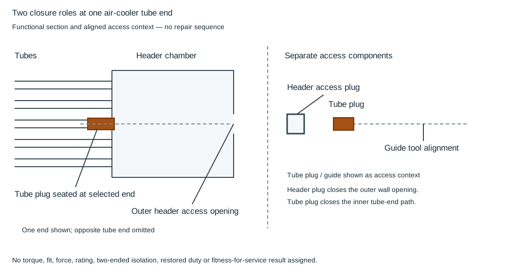
*Figure 6.12. The left panel shows the tube-end plug seated at one tube while the header access opening is shown open. The right panel identifies the separate header access plug and a guide tool aligned with that opening. The juxtaposition explains location and access, not an insertion sequence or repair instruction. Only one tube end is represented.* [Structured closure roles](assets/C06/air-cooler-closure-roles.json).
| Component | Interface and function | Basis to keep with it |
|---|---|---|
| Header access plug | Closes the access opening in the outer header wall; restores that local header-boundary closure | The selected header thread, material, gasket and assembly requirements, including the applicable torque basis |
| Tube plug | Seats at the selected tube end; excludes that local tube-end path from the header | The selected equipment's qualified tube-repair and exclusion basis, with its own plug and verification requirements |
A guide tool shown through the access alignment explains how the inner tube end can be reached through the outer opening. Its presence does not make the tube plug part of the header-plug joint. The [special assembly account](#chapter-c03) addresses header-plug closure requirements. Those requirements cannot be transferred to the tube plug because the part names resemble each other.
The one-end section supplies no plug taper, fit, material, insertion force, pressure rating or repair procedure. It also does not establish isolation at both ends of the tube, restored cooler duty or fitness for service. Keep identification of the two closure roles separate from authorization of a repair. Any accepted tube exclusion changes the equipment's participating flow paths. It can require reassessment of the thermal, hydraulic and integrity basis under [operating integrity](#chapter-c19) and [intervention](#chapter-c20). Preserve the applicable closure checks and return-to-service record for the actual equipment.
### A condensate pocket can consume a pressure-control path's driving pressure
A hot-vapor bypass around a condenser can admit overhead vapor to an accumulator through a pressure-control valve. Its purpose is to influence accumulator pressure, while the main path removes heat and delivers condensed fluid. Vapor in the bypass can itself condense as the line loses heat. A retained liquid pocket then adds a head barrier to the small pressure difference driving the bypass. The resulting problem can be loss of the control path's useful flow, even before a liquid slug reaches the cooler or vessel.
Trace the pressure budget from the upstream bypass takeoff A to the accumulator connection B. At a specified flow and state, define the remaining pressure available against a liquid barrier as
$$
\Delta p_{\mathrm{remaining}}=(p_A-p_B)-\Delta p_{\mathrm{valve}}-\Delta p_{\mathrm{line}}.
$$
All terms are pressure differences in the same unit and on consistent pressure references. The line term represents the selected flow resistance outside the separately stated valve loss. For a static, uniform liquid barrier with effective vertical height $h$, density $\rho$ and gravitational acceleration $g$, its head is $\Delta p_h=\rho g h$. The height is the vertical difference across the retained liquid barrier, not total pipe length. Compare this head with the available pressure under the same state. A nonpositive remaining budget cannot drive the assumed flow through an added positive head barrier.
A liquid barrier consuming the remaining budget eliminates the assumed useful flow; a smaller head still reduces the pressure available for control. This comparison establishes no allowable pocket height or control margin.
A continuously draining bypass is one way to prevent that retained inventory. In the selected arrangement the valve sits above the accumulator and the route drains toward its connection. Another geometry needs an evaluated means of avoiding or removing the liquid barrier while preserving the containment and pressure-control functions. Check condensation, actual connection levels, valve capacity and authority, pressure fluctuations and the participating phases.
The pressure budget neither selects a valve type nor substitutes a static calculation for two-phase flow or transient evaluation. [Flow](#chapter-c07) and [control](#chapter-c22) provide the neighboring methods. [Structured pressure-budget method](assets/C06/vapor-bypass-budget.json).
### Identify where cooling water meets the air or tubes
Water-assisted cooling describes different physical paths. In one arrangement, incoming air passes through a separate water-contact section that washes, cools and humidifies it. A mist eliminator lies between that section and the process-tube cell. The process fluid remains in its tubes. The intended water contact occurs in the air-conditioning section. In another arrangement, water is applied directly over the tube surface, combining evaporative action with the air-side heat transfer at the process cell.
That difference changes the questions for materials, inspection and operation. The separate section has water distribution, collection and mist-removal functions whose condition affects the air reaching the tubes. Mist carryover can defeat the intended separation. Direct wetting intentionally exposes the tube exterior to the selected water and its deposits. Thus external corrosion, fouling, drainage and wet/dry transitions participate directly in the cell's service. Both forms add water inventory, supply and circulation demands, but their water chemistry and inspection boundaries should not be collapsed into one generic cooler property.
A selected winter arrangement can bypass the water-contact section and send air directly to the cell through changed louver positions. Treat that as a defined operating configuration: identify the actual air route, water-system condition, fan/control action and expected duty. A dry bypass does not establish that all required winter performance or freeze protection is available. Loss of water, fan changes and partial operation require their own thermal and process evaluation. Keep these conditions with the equipment selection. Do not assume a device called humidified has one fixed state throughout the year.

*Figure 6.13. Two function-only water-contact alternatives. The first conditions air separately and removes entrained mist before the process cell. Its selected dry bypass changes the air route. The second intentionally wets the tube exterior. Arrows show functional paths, not guaranteed performance or an operating sequence. [Structured paths and states](assets/C06/water-contact-paths.json).*
### Compare both bounds of a preliminary rack envelope
A rack-mounted tube cell has to reach its supports while leaving useful inlet and outlet connection paths. One adopted preliminary arrangement compares rack width $W$ with tube length $L$ using
$$
0.75L\leq W\leq L-2\ \mathrm{ft}.
$$
In this equation, $L$ is the cell's tube length and $W$ is rack width in feet, measured in the illustrated span direction. The lower bound belongs to the selected support geometry. The upper bound preserves the arrangement's nominal total 2 ft connection allowance. These are competing bounds under that particular planning method. They are not a universal rule for cooler frames or every nozzle layout.
Replace the preliminary envelope with the selected supplier's actual frame, support, nozzle and maintenance geometry before commitment. Structural capacity, cell movement, flange/valve access, airflow, lifting and rack routing remain separate evaluations. A feasible numerical width says only that the candidate meets these two planning bounds. A connection projection or different support form can invalidate their applicability without changing the tube length. [Structured preliminary geometry and checks](assets/C06/rack-width-method.json).
## Fired-heater passes combine heat transfer and flow resistance
A fired heater transfers heat from combustion to the process through tubes. A radiant section receives the principal radiated heat. A convection section uses the hot gas on its path toward the stack. Vertical and horizontal or box arrangements place burners, tubes, ducts and access differently. Some selected heaters have both sections, while others have a radiant-only arrangement. The external piping must serve the actual pass and nozzle configuration.
The heater's required heat transfer and allowable pressure loss interact. Sending fluid through more tube length can increase exposure to heating but also increase loss. The equipment designer divides the flow into passes suited to the duty. Each pass has its selected inlet, outlet and flow requirement. The external system must supply that division without assuming that equal nozzle sizes alone establish equal duty.
For parallel passes intended to carry comparable flow, unbalanced pressure loss can create unequal operation. Two-phase service adds the possibility of phase separation at a junction. A selected symmetrical manifold can make lengths, fittings and branches correspond, while balancing valves or other selected controls address their own functions. Geometric symmetry must still be interpreted with the required phases and process conditions. A valve that balances total flow does not necessarily correct an upstream phase split.
The inlet and outlet criteria must remain attributable to the adopted basis. A practice can require geometric symmetry at both inlet and outlet for its two-phase heater arrangement. Another requires inlet symmetry but permits an outlet that is hydraulically balanced without identical geometry. These approaches should not be blended into a rule that symmetry is either always necessary or never necessary. Resolve the applicable criterion and evaluate the actual transfer-line behavior and heater performance.
A vendor-furnished inlet manifold can simplify the field connection but transfers another load and movement interface to the equipment. The supplier needs the piping reactions and any support or spring movement that the manifold connection must accommodate. Independent field routing should not force a furnished manifold into a different geometry. Equipment tubing, manifold and field pipe can have different materials, walls and design bases. Inspect the actual transition and fabrication requirements rather than infer compatibility from nominal size.
Individual pass valves and flow indications can put an operator in a useful position to compare and adjust the selected distribution. The indication should be visible while the related valve is operated. The measurement purpose can be relative balancing rather than custody accuracy, but that does not eliminate the device's installation and phase requirements. [Instrumentation](#chapter-c22) develops the distinction, and [connections](#chapter-c07) develops the physical taps and branches.
Heater location and elevation also affect burners, maintenance and connected flow. Preserve access to firing and inspection positions, tube removal and the selected explosion-door or relief arrangement. A tube or manifold connection can move with the hot equipment. Arrange supports and piping flexibility for that movement rather than treat the heater shell as one fixed terminal. The stack, combustion-air and fuel interfaces belong in the actual selected system. This account does not derive stack height, burner duty or a combustion-control specification from a typical equipment sketch.
### The tube support reference directs movement into the field interface
A furnished heater manifold and an independently supported field ring create different interfaces. A furnished manifold already participates in the supplier's equipment geometry and support arrangement. Its external reactions and permitted movement must be communicated across that boundary. An independent bottom ring can instead be supported from the heater structure or from grade. Those alternatives introduce different structural reactions and relative movement between the ring, heater and field pipe.
Identify where the process tubes are supported before assigning nozzle displacement. For a bottom-supported vertical tube, axial thermal growth proceeds away from the bottom reference, upward into the heater. A tube whose support reference is elsewhere can move its bottom connection differently and impose that displacement on the external manifold. The selected support changes the movement input to the piping evaluation. Calling both connections heater outlets does not make them equivalent. A top connection is another equipment arrangement with a different external route and reference relationship.
Draw the tube support reference, the ring supports and the connection between them in the defined cold and hot states. Compare differential movement and load transfer rather than assuming that a grade-supported ring follows heater steel. Coordinate the actual tube-support design with the heater supplier, including permitted tube growth and equipment attachments. A bottom reference can reduce a particular downward movement demand but does not guarantee acceptable nozzle forces or eliminate piping flexibility work. Materials, temperatures, support contacts and the selected structural restraint still govern the combined system through [analysis](#chapter-c09) and [supports](#chapter-c10).
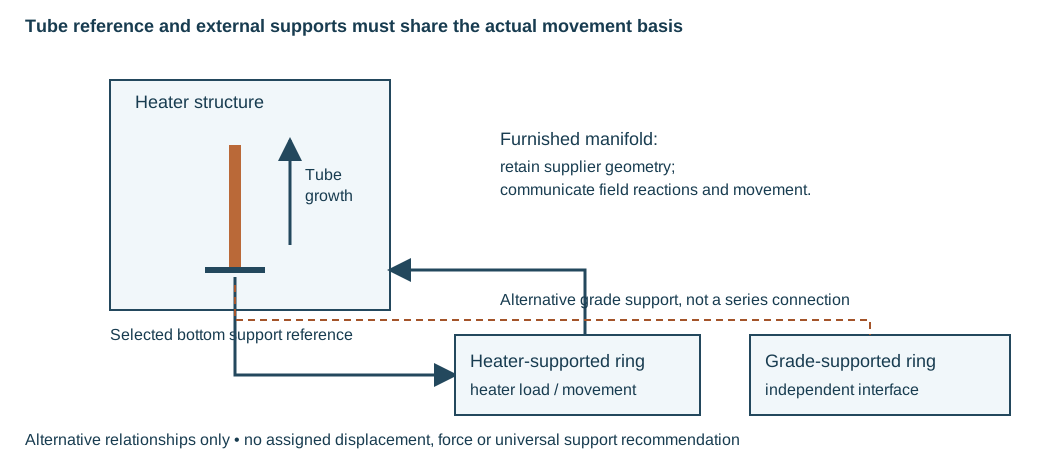
*Figure 6.14. A selected bottom tube-support reference directs tube growth upward. Heater-supported and grade-supported external rings have different movement/load interfaces. The arrows indicate relationships to evaluate, with no displacement, force or universal support recommendation assigned. [Structured entities and movement relationships](assets/C06/heater-support-reference.json).*
### Develop the fuel, air, flue-gas and process paths together
Keep fuel/atomizing services, combustion-air, flue-gas and contained-process paths distinct. In a natural-draft installation, stack, furnace and burner-register resistance determine the pressure profile. A damper changes flue-path resistance; draft-gauge position determines what pressure is observed. Illustrative water-column readings are not universal setpoints.
Changing stack height, duct resistance or heat-recovery equipment requires reevaluation of draft and flow. It does not automatically establish that a fan must be added or that the former settings remain adequate.
Combustion-air preheating can recover heat while adding another configuration. One arrangement transfers heat from flue gas to incoming air in a preheater. A forced-draft fan delivers air toward the burner plenum. An induced-draft fan draws gas through the recovery path.
Another circulates hot oil from convection-section heating through an air-heating coil and back through its selected tank/pump loop. The first adds substantial gas/air duct and fan interfaces. The second adds circulating-liquid, pump and inventory interfaces.
Compare actual heat recovery, flow resistance, utilities, maintenance space and loss-of-supply states before selecting the arrangement. The flow paths identify the alternatives more clearly than assigning them one universal preheater classification.
Fuel and steam services have several different jobs around a burner. In a selected oil-firing arrangement, atomizing steam accompanies oil at the burner to aid dispersion. A coordinated heating/insulation arrangement maintains the oil condition required for useful delivery.
Pilot gas supports ignition. Main fuel gas supplies firing duty. Low points in a fuel-gas path can collect condensate, so the selected drainage and collection destination belong in its service basis. A historical drain to flare is one arrangement, not permission to connect every fuel drain to any available header.
A header box encloses accessible return fittings and plugs separated from the furnace interior by an insulated tube sheet. Its access permits inspection, cleaning and replacement. In a selected detail, a drain with a seal loop and cleanout provides an observation path for leakage, while snuffing steam provides a fire-suppression interface. Observation and suppression are different functions. Neither proves that a leaking process connection is acceptable or that the selected protective system is complete.
*Table 6.2. Similar small service connections can preserve different functions.*
| Connection or assembly | Physical purpose and consequential interface |
|---|---|
| Atomizing steam with fuel oil | Selected burner fuel dispersion; pressure, flow, oil condition and drainage |
| Snuffing steam | Selected suppression destination, local/remote operation and supply availability |
| Soot-blower steam or air | Cleaning external convection surfaces; moving lance, hose or fixed piping and withdrawal |
| Decoking steam/air connections | A defined process-tube intervention configuration, distinct from normal product flow |
| Header-box drain/cleanout | Selected leak-observation and collection path with access |
| Draft gauge and damper operator | Pressure observation and flue-path adjustment at their identified locations |
A burner management package adds sensing, sequence and shutoff functions around the physical burner. Its selected interfaces can include purge conditions, pilot/main-flame observation, admission valves and a response to unsafe heater conditions. Trace those functions across package and field boundaries, including supplies and the operator/control position. A historical manual-ignition drawing or a claim that one burner tolerates many fuels does not establish another installation's permitted fuel, control or protective basis.
Place the operating position so the relevant observation remains available during action. A flow indication used while adjusting a pass valve should be visible from that valve. A burner valve near a peep door can permit the selected flame observation. An oil gun needs its axial removal path, and a retractable soot blower needs carriage and lance travel outside the convection section. Floor-, wall- and roof-fired arrangements therefore impose different working levels and furnace elevations.
Draw those tasks alongside the piping and ducts. A single generic heater clearance cannot represent them.
## Soot and coke create different maintenance configurations
Soot deposits on the external tube surface. Coke accumulates inside the process tubes in susceptible service. Both can reduce the useful heat-transfer function, while internal coke also affects flow. Their removal methods and connections are different. Recognizing the deposit location explains why a soot-blower installation does not supply a complete decoking arrangement.
Soot blowers need their specified supply, drainage, motor or actuator access and lance removal path. Steam routing and condensate removal matter because liquid should not be carried into the hot equipment in a manner that damages it. A vendor-supplied assembly can include piping, while another installation leaves those connections to the field design. Verify the actual scope and keep the movement and removal envelope available.
Steam-air decoking changes the process-tube service and introduces temporary connections. The source-supported arrangement uses steam action and then controlled burning to remove internal deposits, with the selected cooling or other-pass protection arrangements. That description explains why steam, air, water and discharge paths need planned connection and access. It is not an execution recipe. Hydrocarbon removal/isolation, temperatures, flow limits, sequence and monitoring belong to the validated procedure for the selected heater and service.
Some decoking connections are included in the original equipment or piping design even when the associated temporary lines are installed only for the activity. Define where they connect, how temporary piping is supported and handled, and which normal-service connections are restored afterward. The decoking state can impose a different movement and thermal range from production. [Analysis](#chapter-c09), [supports](#chapter-c10), [readiness](#chapter-c18) and [intervention](#chapter-c20) develop those linked evaluations and restoration needs.
A modification can change feed, operating temperature, pass distribution or tube arrangement. Those changes can affect deposit propensity and suitability of the existing cleaning/decoking path. Reconsider the equipment and external system together. Successful previous operation is evidence for its former conditions, not proof that every new duty preserves them.
### Follow both ends of the process pass through a connection change
A decoking connection changes the service of the process tubes. The layout must distinguish the tube pass, the normal process inlet and outlet, the removable connecting pieces and the temporary end connections. A recognizable inlet connection alone does not define the resulting state. The other end must have an identified boundary and a corresponding route for material leaving the pass. Keep that end-to-end account with the selected heater, service and intervention basis.
The boundary model below considers one process pass with a removable connection at each end. In production, the pass connects to the normal process inlet and outlet through those pieces. In the separately defined intervention configuration, the normal process connections are disconnected at the identified joints and their remaining ends have the specified closures. Temporary connections occupy the selected pass-end interfaces. The tube pass remains the same physical object, while the external connection identities change.
This is an illustrative configuration comparison, with both ends defined together. It is not an operating lineup or a sequence for moving the connecting pieces.
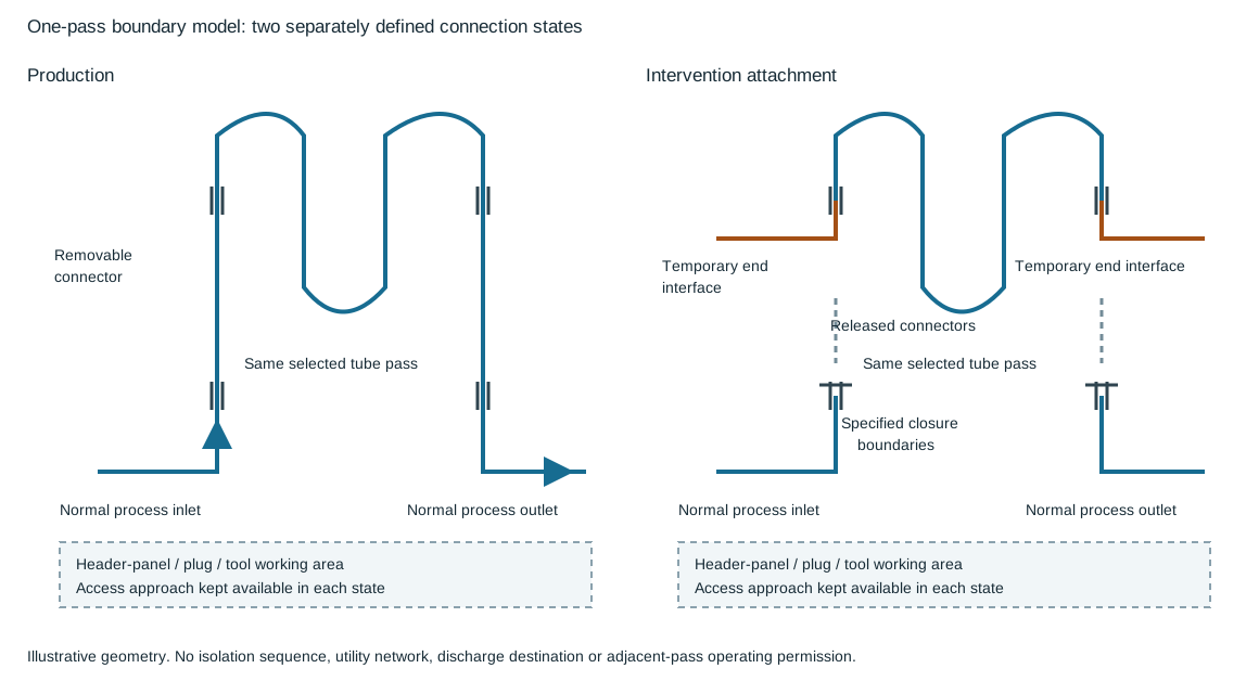
*Figure 6.15. The blue path identifies the tube pass and its normal process connections. The orange marks identify removable connection positions in the separate intervention configuration. The detached process ends and their specified closure boundaries remain visible. Temporary end connections are shown only at the equipment interface. No supply, control, quench or discharge circuit is defined.* [Structured connection identities and states](assets/C06/heater-pass-boundary-states.json).
A swing elbow is one way to make a physical connection removable and redirectable. A removable spool is another. The required disconnection points, bolt access, supporting arrangement and place for the released piece should be apparent in the layout.
When the connector is removed, keep the remaining pipe supported. Evaluate the temporary attachment and its loads under its actual thermal and pressure conditions.
The small diagram establishes which interfaces change. It supplies no isolation effectiveness, load allowable or movement envelope.
Header-box panels and tube-header plugs introduce another access task. The panel opening must be reachable, the removed panel needs a handling position, and the plug or cleaning-tool approach needs its own working space. These paths can be obstructed by a connector that fits during production. Treat the tube-end working area, access door and personnel approach as part of the intervention geometry. Temporary piping that crosses a platform edge also requires the selected protection and subsequent reinstatement. A removed handrail is not a complete access solution.
| Interface in the one-pass comparison | Connection or access question | Restoration evidence to retain |
|---|---|---|
| Normal process inlet and outlet | Which joints release the pass from its production piping, and what closes the remaining process ends? | Intended process route, actual joint and closure identities, affected examination and assembly checks |
| Pass-end temporary attachment | Does it connect to the selected end and remain within the adopted pressure, temperature, material and load basis? | Removal or retained-item disposition and the verified final end connection |
| Swing elbow or removable spool | What must move, what supports the remaining pipe, and where is the released piece held? | Connector reinstatement, orientation, joints and support condition |
| Header-box panel and tube-header plug | Can the panel, plug and tool be handled through their required paths? | Replaced closure parts, applicable joint checks and access-panel reinstatement |
| Platforms and personnel route | What temporary obstructions or protection changes accompany the attachment? | Cleared work route and reinstated selected protection |
The comparison supplies no authority to keep a neighboring pass in production during decoking. Hydrocarbon removal and isolation, tube-temperature protection, operating limits and procedure validation belong to the selected intervention basis. Plan physical connections so that this basis can be executed and checked. Then use [intervention and restoration records](#chapter-c20) to preserve the actual final containment and service configuration.
### Connection alternatives and reverse flow are separate choices
Temporary attachments can meet a heater nozzle, a dedicated heater-tube connection or an external interface opened by a swing elbow or removable spool.
These choices put the releasable boundary in different places. A connection incorporated into the original equipment does not mean its temporary external piping remains installed during production. A convenient outside flange does not establish that the tube pass has the intended internal route.

*Figure 6.16. The upper sketches locate different attachment boundaries at the process-tube end. They are independent alternatives. The lower sketches show the same abstract pass traversed in opposite directions as separately defined intervention states. Arrows stop at the end interfaces and show direction only. The supply and collection arrangements needed to establish either state are outside this drawing.* [Structured physical alternatives and direction states](assets/C06/heater-pass-connection-alternatives.json).
A dedicated connection on the heater tube can change the relationship between the normal nozzle and temporary attachment. A connector exchanged at the nozzle flange gives a different relationship. The selected drawing must identify both relationships and the actual closure of the unused path. With an external swing elbow or spool, identify the fixed joint faces and the connector's two ends. Changing its position changes which fixed interfaces are joined. Do not infer a common interchangeable part merely because two alternative sketches show an elbow.
Forward and reverse decoking flow through a pass are also distinct configurations. Reversing the direction changes which tube end receives the incoming stream and which end discharges the removed material. It therefore changes the duties of the end connections and their attached paths even when the tubes themselves remain unchanged. The selected arrangement must accommodate the required direction and the changed temperature, material transport and pressure conditions. A two-headed arrow through the coil expresses a possibility. It does not supply the connections or validated procedure that establish each direction.
Keep the process-tube path separate from the fate of the removed coke and associated fluid. An accepted intervention arrangement needs an identified collection or discharge interface and an evaluated receiving destination. Historical sewer, pit, drum and stack examples do not establish a permitted destination for another service. Likewise, a sample or erosion-resistant fitting on a particular discharge arrangement belongs to that arrangement's actual material transport and receiving basis. Its presence does not prove that another temporary end connection tolerates the same conditions.
Record the selected pass, connection alternative and direction with fixed interfaces, removable parts, access paths and restoration requirements. Confirm inlet/outlet compatibility, final process routing, joints, closures and support/protection through [technical continuity](#chapter-c21).
### Heat recovery introduces a circulation loop and another operating state
A steam-generation circuit around a convection coil or transfer line exchanger connects heat input to phase change and circulation. An elevated steam drum collects the generated steam and provides a water supply to the downcomer. Heating in the coil or exchanger creates a lower-density vapor/liquid mixture that returns through the riser. The difference between the water-side and mixture-side head can drive natural circulation, while resistance consumes that driving pressure. Drum elevation alone is not proof that the loop circulates adequately.

*Figure 6.17. A function-only natural-circulation arrangement: water descends from the drum to the heated equipment and a vapor/liquid mixture returns through the riser. The contained hot-product path supplies heat across a separating surface. No elevation, density, duty, flow or circulation adequacy is assigned. [Structured flow relationships](assets/C06/steam-recovery-loop.json).*
Keep the two sides of a transfer line exchanger identified. The hot process product follows its own pressure boundary. Water/steam receives heat through the exchanger surface. In a pyrolysis arrangement, the product can pass from convection preheating through a crossover and radiant heating, then through the transfer line exchanger. Repositioning the exchanger changes both that process route and the drum/downcomer/riser connections. Its support lugs, head-removal trolley and bundle or tube work also need their selected paths.
Avoid unintended pockets and evaluate the slope and phase behavior of each actual circulation connection. Long horizontal mixture runs can introduce unfavorable phase distribution or slug behavior. A loop added for thermal flexibility changes resistance and phase geometry. Changing the drum or exchanger elevation changes head and structural/access needs. Compare routing, support and elevation alternatives through the same operating basis.
The selected normal, startup and shutdown conditions may have different heat input, inventory and vapor generation. A pump-driven circuit supplies another circulation mechanism and should be evaluated as a forced-circulation configuration.
The hot product transfer line has a different concern. Susceptible service can form coke in a long route. A shorter route or selected quench near the heater outlet can address that propensity while still needing thermal flexibility, terminal loads and process evaluation. Planned cleaning flanges provide a physical intervention interface. They do not establish a cleaning interval or permit an unreviewed opening of the line.
Waste-heat recovery after a gas turbine introduces an additional heat-source boundary. Turbine exhaust can supply the recovery equipment in the normal selected state. A particular arrangement can also use duct burners when the turbine is shut down. That alternative changes fuel, combustion-air/flue-gas and control requirements. The presence of a burner does not guarantee steam availability following every turbine or utility loss.
Establish the permitted heat-source states with the drum, boiler, feedwater, superheater and bypass arrangements. Verify the actual supplies and selected operating controls. The meaningful comparison is continued function under defined conditions, rather than a generic claim of redundancy.
## Storage form follows inventory and service condition
Storage must contain the inventory in its applicable pressure and temperature condition and permit transfer, observation and maintenance. A fixed-roof low-pressure tank, a floating-roof tank, refrigerated or other low-temperature storage and a pressure vessel impose different boundaries. The same nominal volume does not establish the same foundation, piping or protective arrangement.
A cone or other fixed roof remains in place above the liquid. A floating roof moves with the level and changes the vapor-space relationship. The roof's travel, associated seals or supports and operating limits belong to the selected form. External access and instruments must accommodate that arrangement. Do not treat a moving roof as a fixed attachment location without its design basis.
Low-temperature storage can retain liquefied gases near their boiling condition at the selected pressure. Heat input, pressure, material suitability and the surrounding foundation and containment become consequential. The storage temperature is a service input, not a universal value attached to a product name. Insulation and cold-service supports need their own physical and material basis. Ordinary warm metallic-support criteria cannot simply be extended to cryogenic service. [Materials](#chapter-c02), [special services](#chapter-c13) and [thermal protection](#chapter-c14) develop those requirements.
Horizontal pressure vessels and spherical forms provide another storage arrangement for the selected pressure service. Their support, inspection and piping movements differ from a flat-bottomed atmospheric tank. A vessel type or wall shape does not establish a complete pressure-protection system. [Pressure design and relief](#chapter-c08) carries the selected inventory and upset conditions into the governing basis.
Choose storage dimensions with the site, foundation and operating inventory together. A taller, smaller-diameter tank and a lower, larger-diameter tank can use land and foundations differently. Commercial or shop-fabricated sizes may be useful where applicable. Large field-fabricated storage still needs its actual service and site design. The next methods make the volume and displaced-space parts of that comparison explicit, without supplying a universal tank or dike design.
## Separate liquid volume from final tank height
Determine liquid depth from the required cylindrical inventory and actual inside diameter. It does not establish final shell height: roof construction, operating levels, unused capacity and selected allowances remain separate design inputs. A nominal shell chosen by rounding liquid height alone can omit them.
For containment displacement, use the part of a foundation or berm below the evaluated retained-liquid level. Partial submergence cannot be represented by subtracting the whole solid volume. The geometry must match the actual foundation; a circular-frustum method does not describe an arbitrary rectangular foundation or dike. Keep stored-liquid inventory and submerged solid displacement on their respective sides of the [usable-volume account](#c06-containment).
## Gross enclosure volume is not usable containment
Secondary containment has a function separate from normal storage: it provides a defined space for a release scenario under its adopted basis. The required retained inventory, participating tank failure or spill, other liquid inputs, freeboard and exclusions must be established for the actual service. A historical largest-tank sizing rule does not establish all current requirements for every multi-tank area or liquefied-gas facility. Where the governing basis adopts NFPA 30 for flammable and combustible liquid diking, retain its selected edition, service scope and project conditions. The geometric method here does not extend that basis to all refrigerated or pressure storage.
The usable space at a selected retained-liquid level can be expressed as
$$
V_{\mathrm{usable}}(H)=V_{\mathrm{enclosure}}(H)
-\sum V_{\mathrm{displaced}}(H)
-V_{\mathrm{already\ occupied}}(H),
$$
In this equation, $H$ is the level measured from the defined datum. The enclosure term is the interior geometric volume below that level. Displacement counts the relevant solids and structures occupying that volume under the selected release state. Already-occupied volume represents other liquid whose treatment is specified in the account. Avoid double-counting an item or a fluid. The actual required capacity and selected allowances remain a separate comparison with usable volume.
The method becomes more involved when the interior floor slopes, the wall is an earthen slope or several structures are present. Use the actual volume below each evaluated level or a correctly scoped geometric method/chart. A single plan area multiplied by height can be wrong when the cross-section changes with elevation. A chart for one slope and datum cannot be applied to another enclosure without examining its assumptions.
For multiple tanks, identify what remains inside the enclosure in the selected release state and which volumes the governing basis counts as displaced or available. The treatment of a tank involved in the release should not be invented from its normal operating outline. Soil berms, foundations and other tanks can consume space that a gross-area calculation overlooks. Inventory, displacement, floor grade and the selected retained level must describe the same configuration.
Earthen dikes, concrete walls, secondary tank walls and combined or double-containment arrangements use land, access and failure boundaries differently. An earthen form needs its selected material, slope and support. A compact wall can constrain working space and penetrations. A second boundary can serve a selected additional containment function, especially where the service and nearby exposure make that function consequential. Its presence does not automatically establish independence or an adequate capacity.
[Layout](#chapter-c04) coordinates placement and access. This chapter develops the explicit capacity and equipment-state account.
Drainage is part of that boundary. Minor spills, rainwater and selected other inputs have to follow the adopted collection and disposal route without defeating the intended containment. Establish how drains, sumps and penetrations behave in the release and operating states. An open flow path may drain a normal area while also releasing the inventory the enclosure was intended to retain. No capacity arithmetic can compensate for an unexamined boundary or an incompatible fluid/service condition.
## Foundations and transfer piping must tolerate the selected states
Tank foundations can use a ring wall, compacted fill or a selected concrete arrangement. Their geometry and expected movement affect piping, access and the capacity account. Civil and geotechnical design establishes the actual supporting conditions. The piping arrangement needs those conditions rather than assume that a tank and adjacent sleeper or rack remain at one relative elevation.
Low-temperature foundations add a thermal function. Described alternatives use an elevated concrete base with air space or a foundation with an embedded heating arrangement for the selected cold-release concern. These are particular foundation designs, not a universal instruction to heat every storage pad. Their access, supply, inspection and failure states should remain connected to the stored service and selected containment system.
Settlement can change the tank nozzle relative to pipe supports, a pump or an enclosure penetration. A filled tank, an empty tank and an installed reference can impose different displacement conditions. Route and support the transfer piping for the evaluated relative movements. A fixed bridge across the nozzle and another foundation can turn settlement into terminal load. [Analysis](#chapter-c09) and [supports](#chapter-c10) develop that evaluation with the actual movement and acceptance basis.
Locating a pump inside or outside a dike changes both access and fluid routing. A route over a wall can avoid a penetration but introduce a rise, another suction-head demand or a potential vapor pocket. A penetration can simplify the route while requiring its selected containment detail. Evaluate the lowest operating liquid level, pressure/vapor condition and loss with [the suction-head method](#chapter-c05). Also evaluate the boundary and maintenance task. Neither outside placement nor an over-wall route is a universal preferred solution.
Tank manways, heaters, level instruments, roof access and piping have different maintenance paths. Keep the selected removal and working envelopes available, including what components or temporary equipment occupy them during intervention. A later added line, changed insulation or larger actuator can consume space or alter load. The stored product and pressure/temperature basis can also change what the existing material, roof or containment arrangement can accept.
## Verify the equipment function and the connected configuration
Verify the actual exchanger side/orientation, nozzle/internals configuration, removal paths, phase/drainage paths, support movement/reactions, heater/temporary connections, tank foundation/piping relationship and containment boundary against the same selected equipment and states.
[Quality](#chapter-c16), [construction](#chapter-c17) and [readiness](#chapter-c18) establish their applicable fabrication, inspection and test routes. A pressure test does not prove balanced phase distribution, an available withdrawal corridor or usable spill capacity.
During operation, changing level, temperature, duty, fouling or service can reveal conditions not represented in an earlier arrangement. Maintenance and modification can remove masses or restraints, introduce temporary connections or change an internal flow path. Trace those changes through the equipment and adjoining systems. Retain the actual configuration in [operating integrity](#chapter-c19), [repair and modification](#chapter-c20) and [engineering records](#chapter-c21).
# Chapter 7 — Branches, small-bore connections, vents and drains
## An opening and an attachment occupy the same place
Evaluate both pressure reinforcement of the opening and loads carried by the branch, weld/thread and local parent wall. A pressure-chart selection does not establish capacity for valve/instrument weight, piping displacement or vibration.
The evaluated assembly includes nipples, valves, plugs/blinds, tubing, instruments and discharge piping in normal, startup, test, cleaning and maintenance states. Longer insulation extensions, added valves, stationary instrument leads, temporary hoses, braces and partly dismantled configurations change mass, lever arms, stiffness or imposed displacement even when nominal size and pressure class remain unchanged.
## Choose the branch geometry with its load and fabrication path
A reducing tee and a straight tee with reducer achieve the size change through different geometry and joints. Manufactured branch fittings provide controlled geometry and inspection access, but mass, cost, availability and joint arrangement can favor another eligible construction.
Integrally reinforced outlet fittings place added material around the branch opening as part of the fitting. Butt-welded, socket-welded and threaded outlet forms lead into different joint and small-bore arrangements. A fabricated stub-in connects branch pipe into an opening in the run, with or without a reinforcing pad or saddle where permitted. The opening, branch angle, wall, weld geometry and reinforcing material need the applicable pressure calculation or qualified detail. Reinforcement is not established merely by seeing a pad around the connection.
An adopted branch chart can coordinate the permitted detail with run size, branch size and piping class. Read its notes as part of the chart. One class procedure may prefer tees for particular size combinations. It may permit a stub-in only for defined low-pressure services with a separate reinforcement check and authorization. Another may supply different outlet details.
These are applicable alternatives under their respective class and service bases. An apparently more compact branch is not interchangeable without checking the conditions that selected it.
External loads must follow the actual geometry. A welded outlet carries branch bending into a local region of the parent pipe. The parent wall and attachment can experience stresses different from those of the branch cross-section alone. A pad intended for pressure reinforcement does not by itself establish capacity for every applied moment. The evaluation must include sustained weight, imposed displacement and dynamic effects where relevant, with the weld and local pipe wall considered.
Fabrication and inspection can reverse an economical choice. Access for a sound attachment weld, required examination, cleaning of crevices and later inspection of the vulnerable detail affect long-term integrity. A manufactured fitting can simplify welding and inspection. It can be preferable when the workmanship and inspection demands of a nominally cheaper fabricated connection are difficult to meet.
[Welding and examination](#chapter-c16) supplies the fabrication assurance, while [Mechanical analysis](#chapter-c09) supplies the load evaluation. [Nozzle cutback and dimensional closure](#c17-cutback-method) connects a selected fabricated construction to its actual bore, parent outside surface and terminal datums. That scalar geometry establishes a length reference. It does not supply the complete branch profile, reinforcement or welding qualification.
Threaded and socket-welded branches deserve their local restrictions. Thread roots and weld toes can concentrate cyclic stress. Joint geometry can retain fluid or contaminants. A class that excludes a threaded outlet in cyclic service cannot be satisfied by selecting a thicker nipple of the same nominal size. Material, joint type, geometry and loading must be evaluated together. [Pressure-retaining joints](#chapter-c03) develops those joint mechanisms.
### Geometry restrictions work together
A preference for an outlet fitting is meaningful only within its construction and service conditions. New construction can permit an inline tee before the run is assembled. An existing line that can be isolated can still use an inline butt-welded tee or reducing tee. This requires a different intervention from attaching an outlet to the existing run. A selection list that also describes hot-tap branches does not authorize live work. [Intervention](#chapter-c20) must establish that work's process, material, containment and execution basis.
Consider one specifically adopted outlet-selection basis for conventional and insert-type outlets. It distinguishes duplex from non-duplex lines and applies the following conditions together. These are local eligibility restrictions for that basis, not universal limits on branch fittings.
*Table 7.1. Conditions in the selected outlet method. [Structured conditions and examples](assets/C07/c07-branch-methods.json).*
| Question | Condition in this adopted method | What must remain distinct |
| --- | --- | --- |
| Is the run sufficiently thick for this outlet route? | Actual run outside diameter divided by wall thickness, $D_o/t$, is less than 60 for every duplex outlet and for non-duplex branches of NPS 4 and larger. A separate minimum-wall criterion also applies | Measured or specified actual dimensions, rather than nominal size. The separate minimum wall is not supplied here |
| Is the branch too large relative to the run? | Branch nominal size is no greater than 40% of run nominal size | A ratio of nominal designations, rather than the actual $D_o/t$ calculation |
| Does the material family permit this outlet size? | The weld-on outlet size is limited to NPS 12 on non-duplex lines and NPS 3 on duplex lines | The material family and outlet construction remain attached to the size limit |
| Does the duplex geometry require another strengthening route? | For duplex $D_o/t>60$ or a branch above NPS 3, the basis calls for reinforcing saddles. Full-encirclement arrangements and outlet-neck extensions supply additional strengthening where required | Strengthening/stiffening is still evaluated, rather than inferred from the alternative's name |
The strict less-than condition and the greater-than alternative leave the exact boundary $D_o/t=60$ unresolved in this selection basis. Do not fill that gap by treating equality as permission. Nor can this table replace the separately required minimum-wall criterion, pressure reinforcement or evaluation of external loads. A small non-duplex branch below NPS 4 should not silently acquire the duplex wall-ratio rule, although its other restrictions and mechanical checks still apply.
Service also changes the alternatives. Under this same preference basis, certain split-tee arrangements are restricted to noncorrosive service. An isolated inline replacement and an attachment retained on the existing run have different fabrication and containment consequences. Preserve those conditions when comparing cost, shutdown duration, weld access and later examination. The useful choice is an eligible construction with an evaluated load path and intervention route. Meeting a nominal size ratio alone does not establish that choice.
### A flow model supplies another input, not another strength rating
A process branch has to carry its required flow as well as attach safely. A nominal branch/run percentage describes the selected geometry. It does not calculate throughput, pressure loss or retained phases. Establish the branch's actual flow duty and internal area. Include the states in which it is intermittent, bypassed or partly blocked. A pipe's outside diameter and its nominal designation are different inputs from the area open to flow.
A homogeneous mixture model makes a useful preliminary account when liquid and gas are represented as moving together without slip. At the specified local pressure, temperature and composition, let $\dot m_L$ and $\dot m_G$ be liquid and gas mass rates, and $\rho_L$ and $\rho_G$ their respective densities. The modeled volume rate and mixture density are
$$Q_h=\frac{\dot m_L}{\rho_L}+\frac{\dot m_G}{\rho_G},\qquad \rho_h=\frac{\dot m_T}{Q_h},\qquad \dot m_T=\dot m_L+\dot m_G.$$
For mass rates in lbm/h, densities in lbm/ft³ and internal area $A$ in ft², $Q_h$ is in ft³/h and the common modeled velocity is
$$V_h=\frac{Q_h}{3600A}=\frac{\dot m_T}{3600\rho_h A}\quad\mathrm{ft/s}.$$
The factor 3600 converts hours to seconds. The density follows the volume carried by both phases. Averaging their densities according to mass fraction would give a different quantity. The subscript $h$ identifies this homogeneous model, rather than a measured local holdup or the separate phase velocities of an actual line.
One adopted two-phase sizing screen uses the quantity $\rho_h V_h^2$ with a limit of 10,000 in its specified customary units. With lbm/ft³ and ft/s, that quantity has units lbm/(ft·s²). It is not a dimensionless index or a pressure in psi. The screen does not calculate pressure loss, actual phase distribution, solids erosion, transient slug force or fatigue/mechanical acceptance. [Structured calculation basis](assets/C07/c07-branch-methods.json).
A density at another pressure or temperature changes the volume account. Phase slip changes the relationship between flow fractions and local holdup. Use a suitable hydraulic method for the actual service, then carry its relevant states and forces into the attachment evaluation. [Phase-sensitive equipment piping](#chapter-c05) and [Pipeline inventories and slugging](#chapter-c11) develop those consequences at their system interfaces.
## Small bore can carry a large mechanical demand
The mass of a valve or instrument matters relative to the stiffness and length of its connecting nipple. A longer cantilever places that mass farther from the root and lowers its stiffness. A heavy valve on a short, thick connection can behave differently from the same valve on a longer nipple. Concentrated mass is not equivalent to a uniformly distributed pipe weight.
Vibration adds an inertial force to that static demand. The parent pipe’s motion can excite the attached assembly, particularly when the forcing frequency approaches one of its natural frequencies. A small observed displacement of the main pipe does not establish a small local stress at the branch root. The attachment can amplify motion, and thread grooves, weld toes or abrupt section changes can concentrate the resulting cyclic stress. Fatigue depends on local stress cycles and the material/detail environment, rather than on how impressive the visible motion looks.
Machinery excitation, reciprocating flow, valve instability, cavitation and two-phase flow can all provide forcing, with different predictability. A particular pump speed does not set a universal design frequency for every root valve. The useful approach identifies likely excitation and evaluates the attachment’s response. Where forcing cannot be reliably predicted, it includes observation of the actual operating condition. [Vibration](#chapter-c09) develops the system mechanisms and investigation.
Shortening an unsupported nipple or reducing valve mass can improve its response, but it must still provide the required connection, insulation clearance and access. An added support or brace changes stiffness and the load path. It may reduce local vibration and also oppose the main line’s thermal movement if connected to stationary steel. Select the directions restrained and the relative movement permitted. Do not cure one problem by imposing an unexplained second one. [Supports and restraints](#chapter-c10) develops that installed arrangement.
Two serial valves, an added fitting or a changed actuator can make an apparently familiar detail a different appurtenance. The assembly’s mass distribution and moment arms should be reevaluated. If the connection is sufficiently stiff, measured accelerations of the attached masses can provide a useful route to estimating cyclic bending at its base. The method below illustrates that route. It does not replace the parent-pipe local check or a modal analysis when flexibility is important.
### A lumped-mass check explains what must be measured
For a stiff appurtenance represented by discrete masses, the inertial force in one selected direction is
$$F_i=m_i a_i,$$
and the moment about the selected base section is
$$M=\sum_{i=1}^{n}m_i a_i l_i.$$
In this equation, $m_i$ is the mass of item $i$ and $a_i$ is its acceleration in the selected bending direction. The variable $l_i$ is the corresponding perpendicular moment arm to the section. With kilograms, meters per second squared and meters, force is in newtons and moment in newton meters. Use mass, not a force labeled as weight. If an input is a weight force, divide it by the appropriate gravitational acceleration to obtain mass in a consistent unit system.
For a sinusoidal evaluation, accelerations and moment must be treated with their relative signs and phases. The sum of individual amplitude magnitudes is a conservative bound on the magnitude of their combined moment in this model. It is not automatically the measured amplitude when the masses move out of phase. The selected direction also matters: the same assembly can respond differently in perpendicular directions.
A bending-stress estimate for the selected section is
$$\sigma_a=K\frac{M_a}{Z},\qquad Z=\frac{\pi(D_o^4-D_i^4)}{32D_o},$$
In these equations, $M_a$ is bending-moment amplitude and $Z$ is the elastic section modulus of an annular section. The variables $D_o$ and $D_i$ are its outside and inside diameters. The variable $K$ is the applicable geometric stress-concentration factor for the evaluated detail. $K$ is dimensionless; $Z$ has units of length cubed. With moment in N·m and $Z$ in m³, stress is in pascals. The formula models elastic bending of the chosen section.
The appropriate local-detail factor and fatigue basis are separate inputs, and the parent pipe at the attachment still needs its own local stress evaluation.
Associate acceleration with direction, location, phase and operating state. Stress range is twice amplitude only for a symmetric fully reversed cycle; compare like quantities under the actual fatigue criterion.
#### Locate the masses and the section before assigning moment arms
Figure 7.1 connects a two-valve assembly to the rigid-appurtenance model. The connection has two 18-lbf valves on short intervening nipples. The model replaces each valve by a mass at its center of mass. Bending demand is to be evaluated at the selected base section A. That section is not the valve-body edge or parent-pipe centerline.
In the illustrated model the nearer center is 2 + 5.5 = 7.5 in from A. The farther center is another 6.5 in away, giving 14.0 in. These are the exemplar's model distances.

*Figure 7.1. A conceptual physical assembly and its paired lumped-mass model. The model carries centers, base section and distance chain explicitly. For acceleration along Y, perpendicular to the model's center-to-base line in this plane, the displayed distances are the perpendicular arms. Valve shapes are schematic. The model distances are not fabrication dimensions. [Structured geometry and unit data](assets/C07/c07-hardware-inertial-model.json) preserve the association.*
A weight of 18 lbf gives $m_i=18/386=0.04663$ lbf·s²/in under the exemplar's gravity convention of 386 in/s². With $a_{1Y}$ and $a_{2Y}$ in in/s², the signed moment in lbf·in is therefore
$$M_A=\frac{18}{386}(7.5)a_{1Y}+\frac{18}{386}(14.0)a_{2Y}
=0.34974a_{1Y}+0.65285a_{2Y}.$$
Division by gravity is essential: multiplying a weight by gravity would not produce mass or these coefficients. Acceleration may instead be reported as a multiple of $g$. Then the numerical force is $18(a_Y/g)$ lbf and the coefficient convention changes. State the acceleration unit before using either expression. The label “18-lb mass” by itself does not establish a consistent force calculation.
The arm is selected from geometry and force direction. In vector form $\mathbf M_A=\sum\mathbf r_{Ai}\times m_i\mathbf a_i$, where each $\mathbf r_{Ai}$ points from A to a center of mass. For collinear centers at distance $s_i$ and acceleration making angle $\theta$ with that line, the bending arm is $s_i\sin\theta$. It equals $s_i$ in the illustrated perpendicular direction and becomes zero for acceleration along the line in this idealization. The latter case still produces axial inertial force.
Out-of-plane acceleration produces bending about a different axis. Actual off-axis centers can also produce torsion. Preserve those distinctions instead of using the branch length for every measured direction.
Combine signed accelerations with their relative phases; an opposite-phase response is not the sum of magnitudes. The rigid approximation must remain plausible. Significant relative deformation requires modal response evaluation. Carry the moment to the selected section modulus/detail factor and assess the local parent attachment separately. Geometry and moment alone establish no fatigue allowance or operating limit.
## Vents and drains must communicate with the retained inventory
A vent is placed to release gas from the relevant volume. A drain is placed to remove liquid. High and low points are useful starting descriptions, but they refer to the actual piping configuration and fluid path. A vent near the highest point of one segment cannot empty a gas pocket separated from it by a closed valve or blind. A drain upstream of a retained low pocket cannot empty that pocket merely because both belong to the same line number.
During filling for a liquid test, trapped gas can remain in a local high point. The vent path must reach that pocket within the defined test boundary. During draining, liquid can remain in low sections, branches, valve cavities or equipment connections. Gas admission and a suitable discharge path may be needed for the intended draining action. The surrounding isolation and service conditions must be respected. [Testing and readiness](#chapter-c18) develops the actual filling, testing, drainage and restoration procedure.
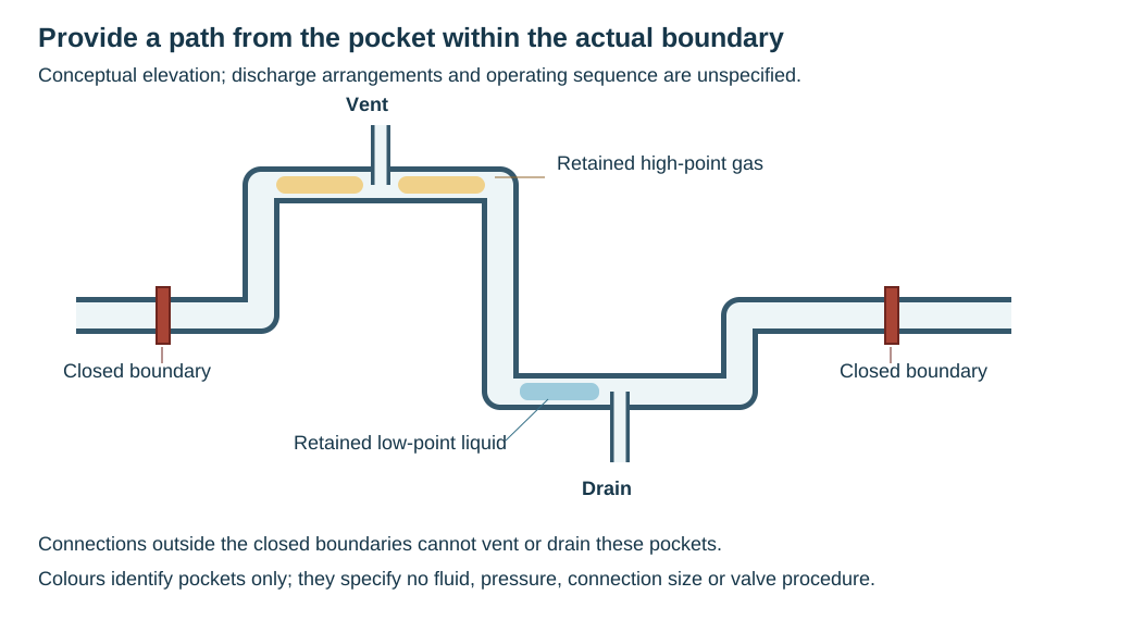
*Figure 7.2. The conceptual elevation shows one isolated segment with its own high-point vent and low-point drain. Closed boundary valves separate it from neighboring piping. The connections describe communication with the pockets. No fluid, size, valve sequence or discharge destination is specified.*
Testing and operating connections can serve different duties. Under a test-connection procedure, hydrostatic vents and drains can be construction-drawing connections used for the leak test. They can have temporary valves where required and permanent plugs, caps or blinds afterward. Operational or maintenance vents and drains can require permanent valves and closure devices, shown on the process and piping drawings and accessible to personnel. The distinction governs hardware, records and reinstatement. A temporary test arrangement is not automatically an operating vent, and a convenient drawing omission does not erase a physically necessary test connection.
Opening a vent or drain can release pressure, hazardous fluid or a hot inventory. Connection size, closure, isolation and discharge destination must support the intended duty. A drain used repeatedly for maintenance needs a practical operating position and a route for the removed contents. An atmospheric discharge acceptable for one harmless test medium may be unsuitable for process service. [Utility architecture](#chapter-c12) and [Hazardous services](#chapter-c13) develop receiving-system and exposure conditions; [Pressure protection](#chapter-c08) develops trapped pressure and thermal relief.
## A connection detail carries its notes as well as its shape
Select the connection family with the material class, header size, duty and required joint/examination basis. Threaded, socket-welded and butt-welded assemblies do not have the same fatigue, crevice or fabrication consequences. A fully examined welded system can call for a flanged construction that preserves its examination route. An extended-body root valve can reduce separate pieces but changes mass, geometry and repair choices. Two root valves change isolation capability and increase the attachment’s length and mass.
Plastic-lined piping needs a connection that preserves the lining through the branch or instrument tee. PVC/CPVC, polypropylene, tubing and ductile-iron arrangements use their own joint systems. The metallic connection’s detail cannot be transferred by replacing only its material name. Compression fittings require the specified tube dimensions and assembly. A flanged nonmetallic connection needs its own load distribution and bolting treatment. [Materials](#chapter-c02) and [Joints](#chapter-c03) establish those compatibilities.
Changing the selected detail also changes the material take-off. A project substituting an integral outlet for a separate nipple assembly must make the class/detail relationship and permitted uses explicit. This keeps early procurement and final design consistent. A drawing selected in one area should not quietly introduce a component excluded by the governing material specification in another.
Insulation creates a practical conflict with an unrestricted preference for short nipples. The connection needs enough extension to keep the required valve, closure or joint accessible without compromising the insulation’s function. One adopted connection procedure specifies an insulated-pipe nipple length of at least 75 mm or the insulation thickness plus 25 mm, whichever is greater:
$$L_n\geq\max(75\ \mathrm{mm},\ h_{ins}+25\ \mathrm{mm}).$$
$L_n$ is nipple length and $h_{ins}$ is insulation thickness in that procedure. The original paired inch values are 3 in and 1 in plus insulation thickness. They are alternative rounded unit conventions, not exact conversions. Use one specified unit basis consistently. This condition is not a universal length rule or a vibration acceptance test.
If the extension makes the attachment mechanically unsuitable, change the assembly or support arrangement rather than silently violate either requirement.
### Follow the closure, valves and joint system through the detail

*Figure 7.3. Selected test closure and operating root hardware motifs.*
A test plug closes the selected test vent or drain after its communication duty. A blind flange provides a different closure and a bolted sealing interface. A single operating root adds a valve between the process attachment and its specified end closure. A dual-root arrangement adds another valve and connecting length. The two valves increase mass and extension as well as changing the available isolation arrangement. Their number alone does not establish a verified intervention boundary.
The illustrated threaded test tee and single-root arrangement are distinct from the selected socket-weld dual-root construction. Its process-side valve has socket-weld ends, while its outer valve provides the specified socket-weld-to-threaded termination for a plug. Preserve those end types and the intervening plain-ended nipples in the material take-off. Do not substitute a threaded assembly because its symbols look similar. A line-class choice and header-size range select the actual construction. The dimensionless motif selects neither.
The lined instrument tee preserves its lining through a dedicated tee and uses its flanged valve and blind closure. The lining, tee geometry, valve ends and bolted seals form one pressure and chemical boundary. Replacing that motif with a drilled bare-metal outlet discards the lining duty. Conversely, a lined flanged detail does not provide the joint system for PVC/CPVC, polypropylene, tubing or ductile iron. Those retain their own specified sockets, flanges, fusion, compression or mechanical joints.
[Structured variant relationships](assets/C07/c07-root-closure-motifs.json) identify the interfaces. Select the actual class/detail with its header-size and material notes, insulation extension and evaluated mass/support/access. Changes to outlet or valve ends must reach the class, detail and purchase record.
*Table 7.2. Connection duties and installation consequences.*
| Connection duty | Distinction to preserve | Installation and operating consequence |
| --- | --- | --- |
| Hydrostatic test vent/drain | Defined test boundary and high/low pocket; temporary versus permanent hardware | Filling and emptying communication, then specified permanent closure and reinstatement |
| Operating or maintenance vent/drain | Repeated duty, accessible valve/closure and discharge route | Safe operation, isolation, contents removal and condition inspection |
| Pressure instrument root | Pressure communication and isolation plus attachment mass | Root-valve integrity and instrument removal without assuming measurement performance |
| Thermowell | Pressure-retaining connection plus an immersed cantilever | External connection integrity and separate flow-induced response of the well |
| Orifice flange taps | Two pressure leads, their root connections and service conditions | Compatible isolation/support and maintained differential-pressure paths |
| Sample connection | Representative withdrawal arrangement, containment and mechanical connection | Service-compatible sample route and intervention; local branch strength alone does not establish sample quality |
### Entry geometry must permit the intended work
Connection height and sensor insertion solve different problems. A perpendicular thermowell connection, an oblique lateral entry and an entry along an elbow create different insertion paths. Selected small-header arrangements can enlarge a short barrel between reducers to make room for that path. Other material and size families use a tee, instrument tee or tapped flange instead. A mounting projection or locally enlarged pipe does not establish the well's effective immersion, representative sensing or flow-induced response. Coordinate those separate evaluations with [temperature measurement](#chapter-c22) and the actual well geometry.
Reduction can also create a retained pocket. A selected pipeline thermowell arrangement uses eccentric reduction with its flat side at the bottom where a pocket-free horizontal path is required. Its vertical arrangement uses another geometry. The practical question is whether the actual internal path drains and communicates as intended. Transferring that orientation to every reducer would discard the conditions that made the detail useful. So would importing a metallic outlet weld into a lined or polymer assembly.
Orifice pressure taps illustrate a different access conflict. Staggered nipples and 45° elbows can separate adjacent valves and their ends, while leaving no straight path to rod out a blocked connection. In one adopted double-valve orifice-tap detail, the rod-out variant removes the 45° elbows. It rotates the orifice flange by one bolt hole and uses two nipples each 100 mm long. The paired drawing convention is 4 in.
This is a selected geometric alternative, not a general field instruction: preserve the actual pressure-tap orientation, measurement arrangement, class/material construction and permitted intervention. Resolve those interfaces before choosing the access variant.
The same detail calls for support when two valves are at the end of an elbow or nipple because their moment arm loads the root. Providing rod-out clearance does not remove that demand. Changing nipple length or valve position changes it. The support must carry the evaluated assembly load while preserving the parent pipe's relevant motion and the sensing lead's function. Two serial valves alone do not establish an intermediate bleed, demonstrable isolation or permission to open the connection.
Valve removal can leave a lead/fitting unsupported. Rod-out requires a withdrawal/tool path and an established containment procedure. Preserve those configurations and restore selected valves, closures, supports and sensing paths after work.
## Sensing and sampling have mechanical interfaces
The pressure root connection, instrument tubing and instrument support form a load and movement path as well as a fluid path. A stationary instrument connected to a moving pipe needs a lead arrangement that accommodates the relative movement. Tubing secured along the line can follow it. The transition to a stationary support must not impose an unintended restraint or sharp cyclic bend. An instrument mounted directly on a long root connection adds its mass to the appurtenance.
Pressure leads can encounter pulsation, retained liquid, blockage or contamination. Root-valve and connection geometry must preserve the required pressure communication and the maintenance isolation arrangement. Their mechanical adequacy does not establish measurement accuracy. [Instrumentation](#chapter-c22) explains the sensing conditions, impulse arrangements and control function, while this chapter establishes the pressure boundary and mechanical interface.
A thermowell introduces an immersed cantilever into the flow. Its wake can excite the well by vortex shedding. The external nipple/valve assembly’s natural frequency is a different evaluation. Flow velocity, well geometry and the relevant structural response enter the thermowell check. A connection selected for pressure alone does not establish that the inserted well will resist flow-induced fatigue. The instrument chapter owns the temperature-measurement arrangement and the mechanical-analysis chapter develops vibration evaluation.
A sample point likewise has two duties: obtaining the required fluid sample and preserving containment during withdrawal and intervention. Fluid phase, retained pockets and the withdrawal arrangement affect the sample. Valve mass, connection geometry and discharge/support affect the physical installation. Keep both interfaces visible instead of treating a sample valve as an ordinary spare branch.
## Inspect the vulnerable detail and reevaluate changes
Inspect attachment welds, thread roots, nipple transitions, support contacts and hidden insulation/deposit surfaces. Vibration evidence must represent active equipment and flow states; shutdown behavior does not establish response during startup, slugging or changed pump combinations.
A cracked or leaking attachment calls for a diagnosis of the mechanism and affected boundary. A brace that arrests visible motion may leave a crack or introduce harmful thermal loading. Removing a vibrating instrument reduces mass but can also remove a needed sensing or protective function. The intervention must restore all required duties, with the examination, repair and return-to-service route in [Operating integrity](#chapter-c19) and [Modification](#chapter-c20).
Change records should identify the actual assembly. A second valve, thicker insulation, heavier actuator, longer temporary hose or relocated support changes the former analysis basis even when the connection designation is unchanged. Reevaluate the root, parent pipe and attached lead together. After testing or maintenance, restore permanent closures, selected valves, supports and insulation, and confirm that intended communication and isolation paths remain available.
# Chapter 8 — Instrumentation, measurement and control systems
## Decide what information or action the system needs
Use the adopted P&ID legend and instrument information to distinguish indication, recording, alarm and control. A local operating comparison may not satisfy accounting or protective requirements. The symbol does not establish range, accuracy, material, action or accessible mounting.
Keep ordinary regulation distinct from protection. A control valve can regulate a variable without providing an independent response to every hazardous departure. An alarm is not automatically a shutdown, and a valve-position indication is not proof of containment. [Pressure and protective basis](#chapter-c08) and the safety/service chapters establish those functions. This chapter explains measurement and control, while [component behavior](#chapter-c03) and [physical connections](#chapter-c07) explain the hardware interfaces supporting them.
## Trace the complete sensing-to-action path
Begin with the physical quantity and its location. Pressure at a nozzle, metal skin temperature, fluid temperature inside a line and vessel liquid level are different measurements. A nearby connection may be convenient yet sense another condition from the one the function needs. Define where and in which operating states the information must be representative.
Then follow the path to the reading or action. Local gauges can provide direct observation at the equipment. A sensing element connected to a transmitter can support a remote indication, record or controller. Mechanical, pneumatic and electrical arrangements have their particular connection, routing, supply and maintenance needs. Describe the selected signal arrangement without inferring the capabilities of an unspecified control system.
A sound installation preserves both the process and information interfaces. A pressure boundary and isolation arrangement can be mechanically satisfactory while a trapped, blocked or unsuitable sensing path gives a misleading reading. A calibrated transmitter can accurately reproduce a signal that does not represent the vessel or line because its process connection is in the wrong state. Conversely, a correct sensing position can be useless if its local display cannot be read or its signal path cannot serve the intended receiving device.
## Temperature measurement needs the right contact and removal space
Temperature sensing begins with the intended quantity. An inserted probe measures through its contact with the internal service and its selected construction. A skin-temperature attachment measures the wall at its attachment. Neither should be assumed to stand for the other under every heat-transfer condition. Define whether the function concerns fluid, wall or another equipment temperature, then select and position the actual element.
When incoming streams mix, the sensing position also needs to represent the temperature the function is intended to use. A probe close to a junction can see an incompletely mixed region rather than the eventual combined stream. Coordinate the selected mixing and location basis with the actual flow, phase and purpose. A historical diameter-distance detail is not proof that every junction is representative at that distance.
A local temperature indicator combines the sensing arrangement with a readable indication. Fixed and swivel-headed forms put the face in different positions. A thermocouple arrangement provides an electrical temperature signal for a receiving instrument. Filled-capillary arrangements transmit through their sealed working system and specified tubing. Their connection and location requirements differ. The piping layout should not assume that all temperature elements can be inserted, bent or extended in the same way.
A thermowell protects an inserted element and provides a selected pressure-boundary and access arrangement. Its immersion and the connection projection must suit the actual pipe or vessel and sensing requirement. A common center-reaching example is not a universal immersion rule. The instrument, thermowell and connection must fit together, and the selected materials and rating must suit the service through [materials](#chapter-c02) and [connections](#chapter-c07).
Two nearby thermowells can collide inside a pipe even when their external couplings fit. A check-point thermowell and an operating element therefore need their actual insertion paths and lengths. Stagger or reorient the selected connections where needed to avoid interference. Do not discover after erection that one element cannot be installed. Thermowell vibration and mechanical suitability are also part of the selected installation, with [mechanical analysis](#chapter-c09) where required.
Outside the pipe, reserve the complete element and withdrawal envelope. A coupling clear of an obstruction may still leave no room to pull the instrument. A horizontally projecting assembly can occupy a walkway after the element and head are installed. Gauge orientation should also preserve readout and the selected weather/service condition. The required space follows the actual instrument and task, not a historical default clearance number.
A sealed capillary assembly is not ordinary field tubing. Its specified length and integrity form part of the sensing system. Cutting or extending it can defeat that basis. Coordinate the sensing point, receiving instrument and available route with the selected length, or choose another supported arrangement. A source-era economic length range does not establish a present universal limit or a substitute design for a new installation.
### Distinguish the external outlet axis from the installed well
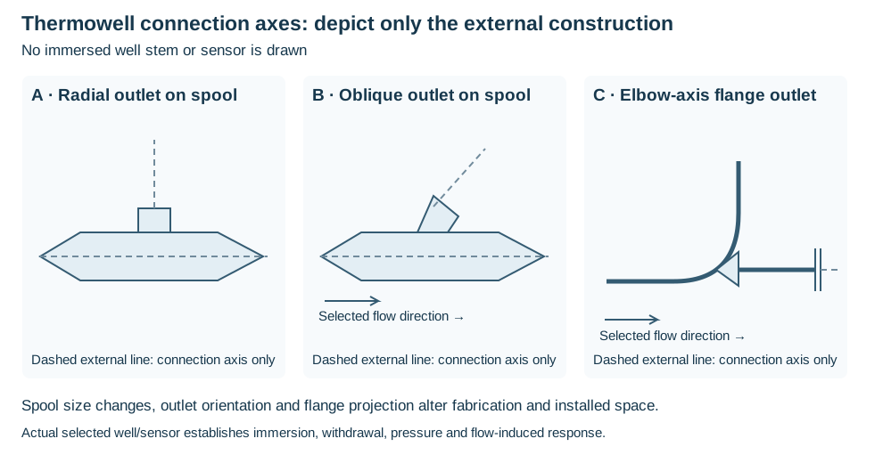
*Figure 8.1. External thermowell outlet and spool alternatives.*
A radial threaded outlet and an oblique threaded outlet establish different external connection axes. In the selected small-line arrangements, size-changing fittings surround an enlarged straight spool before returning to the line size. A larger-line variant attaches directly to the line. An elbow-axis arrangement instead uses its specified outlet on the elbow, a projecting pipe length and a flange boundary. Those choices alter fabrication, end preparation, mass and installed space before the thermowell is fitted.
The selected oblique and elbow details carry flow arrows. Retain them with those details rather than turn them into a preferred direction for every temperature connection. A threaded outlet, threaded lateral outlet and socket-weld/flanged elbow outlet also have different joint systems. Match the actual header size, line class, material and end preparation, including the source detail's particular spool/projection dimensions. The [structured external-axis comparison](assets/C22/c22-thermowell-external-axes.json) records the selected construction without prescribing those catalog dimensions for another installation.
Only the external construction is shown. The dashed projection identifies an external connection axis, not an immersed stem, sensor tip or withdrawal envelope. Use the selected well and instrument to establish actual insertion, fit, removal and the mechanical conditions already described above. An outlet-axis drawing cannot establish sensing accuracy, pressure adequacy or wake/fatigue response. Carry the actual well geometry into [Mechanical analysis](#chapter-c09) and its physical space into [Access and handling](#chapter-c04), while [Fabrication](#chapter-c17) verifies the spool and end interfaces.
## A pressure tap senses one location and one state
Pressure indication can be local or transmitted to a receiving function. The tap, root connection, valve, tubing and instrument define both a pressure boundary and a sensing path. Preserve the material/rating break and the physical scope of each participant. A small instrument connection is still exposed to its applicable process condition. Its size does not justify an unsuitable first nipple or valve.
Locate the sensing point for its purpose. A controller regulating a downstream pressure needs information representative of that controlled region. A location immediately affected by a junction, throttling action or unstable flow can have a different signal from the one intended. The required separation and geometry depend on the selected service and instrument basis.
One location basis allocates at least six pipe diameters after a control valve or intersection. A different pressure-mixing/controller example specifies a 30-diameter minimum downstream of its junction. These are separately scoped criteria, not interchangeable measurements or a reason to adopt the larger value automatically. Retain the actual disturbance, tap purpose and diameter convention of the selected basis, and evaluate the resulting location.
Elevation and sensing-path contents can change the pressure reaching the device. In a known continuous liquid-filled path at rest, pressure increases downward with liquid density and vertical depth. A gas pocket, changed liquid, two-phase path or selected condensate leg needs its actual head/reference basis. [Pressure-reference and elevation accounting](#c18-pressure-method) provides the bounded static-head method.
Tie any zero or elevation correction to the selected hookup, fill fluid and instrument procedure. It is an installation correction, not automatically a process-pressure change or a generic subtraction from every gauge.
Keep measurement separate from pressure protection. A control valve can reduce normal downstream pressure while a different open, blocked or failed configuration exposes a region to a higher pressure. Where that credible state applies, a class break cannot be justified solely by the normal controlled reading. [Pressure design](#chapter-c08) establishes the actual exposed boundary and protective basis. The pressure measurement and control layout must represent the same conditions.
## Flow measurement depends on the physical stream and approach
A flow device needs more than a line number and a convenient straight segment. Define the fluid, phases, pressure/temperature, expected range and measurement purpose. Process indication, control, custody accounting and leak-detection applications can have different acceptance targets. The adopted range and uncertainty basis should describe the conditions in which the device will operate, not merely its nominal size.
Differential-pressure arrangements such as an orifice assembly use a specified primary element and sensing connections. A transmitter receives the selected pressure difference and supplies the indicated, recorded or controlled flow function under its calibration basis. A venturi or an averaging pressure device uses another selected geometry. The configuration affects the approach, required lengths, taps, pressure loss and maintenance. Do not replace one form with another solely because it fits without reevaluating the measurement and process consequences.
Upstream bends, valves, branches and other disturbances affect the flow presented to the primary element. The selected straight-run basis must match that configuration and the meter's dimensional ratios. A length expressed as pipe diameters is not meaningful until its diameter and conditions are defined. A code or guide referenced historically does not establish a current requirement without its applicable edition and configuration.
For an orifice, retain diameter ratio $\beta=d/D$ with orifice bore $d$ and corresponding pipe inside diameter $D$. A selected straight-run factor in pipe diameters multiplies that actual diameter. The applicable disturbance, ratio, meter basis and edition determine the factor; nominal size alone does not establish the run.
When a selected meter run does not fit, compare meaningful alternatives. Another validated element, a different route or a selected flow-conditioning arrangement may recover space, but can change pressure loss, maintenance and the measurement basis. Ask which engineering result each alternative must preserve rather than shorten a run without examining the source of its requirement.
Tap orientation and small-piping arrangement also matter. Liquid, vapor, steam and solids-containing service can require different selected hookups. A staggered tap arrangement can solve valve or flange interference while being incompatible with a prefabricated manifold. Keep the actual device, sensing connections and process phase together. [Connection details](#chapter-c07) develops the physical forms. Their geometric fit does not itself validate the measurement.
## Phase and operating window limit what a reading means
A liquid-service meter or control arrangement should not be credited for the same function after upstream flashing changes its inlet. [Phase-sensitive equipment paths](#chapter-c06) shows how elevation and loss can cause that change. Evaluate pressure, temperature, density and the actual device basis, preserving the state in which the measurement is to be used. A layout drawing cannot establish single-phase operation by itself.
That limitation is different from saying that all two-phase or multiphase flow is impossible to measure. The admitted service material includes wet-gas and full-wellstream measurement arrangements. A wet-gas arrangement can use a gas-meter basis with selected correction for liquid effects. A full-wellstream system may determine quantities for more than one phase. Some selected systems do not distinguish different liquid phases. Their output, uncertainty and operating window need their own definition rather than inherit a simple liquid-meter calibration.
Flow and phase proportions can change over facility life. Gas-volume fraction, water fraction, composition, rate, pressure and temperature can move the stream outside a device's stated range. A measurement satisfactory at most conditions can still be unsuitable for a consequential interval. Select or plan alternatives around the required operating window and purpose, not a single early duty point.
Different calibrated ranges, parallel meters, exchangeable elements or selected non-intrusive arrangements can support that changing duty. A long-term change may permit a planned shutdown for an element replacement, while another service cannot tolerate frequent containment breaks. Selected computational compensation can use additional condition/composition information where the admitted metering basis supports it. Compensation is not proof that an unmeasured input or an out-of-range device becomes valid. The selected compensation method still needs its actual inputs, validity range and verification.
Do not universalize a project-specific uncertainty percentage or a lifetime-coverage target. Preserve the required output and operational window for the actual contractual, reservoir, process or protective purpose. The technology and the installation must be evaluated against that purpose, including how a changed element, calibration or bypass affects the rest of the system.
## Level instruments sense a physical relationship
A local level gauge makes the selected liquid level visible through its communicating arrangement and readable range. Reflective glass, for example, has a particular viewing side. Segments or multiple gauges can cover a larger range, but their visible overlap and connection positions must reflect the actual assembly. A nominal gauge length is not necessarily its readable span.
An external cage or chamber communicates with the vessel through its selected connections. A float or displacer then responds to the liquid condition in that chamber. The instrument can represent vessel level only while the communicating arrangement is in its required state. A blocked connection, trapped phase or an isolated cage can leave the instrument sensing a different inventory. Correct calibration of the device does not correct that physical difference.
An internal float or displacer places the sensing assembly within the vessel instead. Its withdrawal connection, range and access differ from an external cage. Some selected arrangements cannot be isolated for removal in the same way. Compare the actual maintenance configuration and process service, not only the smaller footprint of the installed device.
A suspended displacer senses a density-dependent change in apparent load as immersion changes. It differs from a floating element. Its spring or torque-tube response, range and calibration must suit the actual liquid density/specific gravity and selected mechanism. A service-density change can alter the indicated level without the same change in inventory. The mechanism and pressure boundary remain particular to the selected device.
### Coordinate the bridle, chamber and readable gauge span
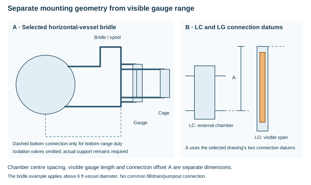
*Figure 8.2. Selected bridle and gauge mounting geometry.*
A selected horizontal-vessel arrangement above 6 ft diameter uses a communicating pipe spool or bridle to avoid excessively long separate connections. The bridle carries the physical gauge and external chamber connections. Its lower extension to a vessel-bottom connection is a distinct option used only when the required range extends to the bottom. Do not make it the default merely because a drawing shows it.
The diagram omits isolation valves for clarity. The actual gauge arrangement retains dedicated block valves and the vents/drains needed for its prescribed cleaning and intervention. The installed support must suit the mass, projection and service movement.
Keep the external displacer chamber, denoted LC in the selected construction, separate from the visible level gauge LG. Chamber connection center spacing describes one geometry. Visible gauge length describes what can be read. The elevation difference A compares the specified LC and LG connection datums. These are not a differential-pressure calibration diagram or interchangeable dimensions. A correct overall mounting height does not establish complete readable coverage between segmented gauge windows.
One class-specific mounting table applies to ASME Classes 150, 300 and 600. It relates a 356 mm chamber center spacing to one two-element gauge with 670 mm visible length and A from 90 to 394 mm. A separate 813 mm chamber spacing uses one three-element gauge with 1,036 mm visible length and A from 102 to 315 mm. Its 2,134 mm chamber-spacing row instead uses two two-element gauges plus one three-element gauge. It has 2,326 mm visible length, a standpipe and A from 102 to 284 mm.
These selected rows illustrate the different references. Their A convention assumes that the individual gauge with the longest visible length is placed at the top when several gauges are required. They do not dimension another product, pressure class or segment sequence. The [structured mounting relationships](assets/C22/c22-level-mounting.json) preserve those exact selected rows and conditions.
Keep the communicating connections dedicated to the level arrangement. The selected vessel mounting basis excludes sharing them with fill, drain or pumpout services. Establish the actual cage and gauge, material/rating, readable overlap, valve access, cleaning path and support before releasing the installation. [Small-bore connection duties](#chapter-c07) and [Work envelopes](#chapter-c04) provide the connected physical checks. This mounting account adds no control architecture.
## Calibration and installation have different errors
Checking a receiver's range or a transmitter's response can establish only part of the sensing chain. It does not prove open, representative process connections or free displacer movement. Nor does it prove that the indicated quantity uses the right fluid condition. A nearby check-point thermowell or local gauge can support a comparison. Before one reading is simply declared wrong, a difference should be investigated through the actual sensor, connection, reference and state.
Changed service can reopen the calibration basis. Density, phase, temperature or flow range can change the relation between a physical quantity and the signal used to infer it. Reevaluate the affected sensing and conversion rather than assume that an unchanged instrument tag means an unchanged valid measurement. [Operating integrity](#chapter-c19) and [engineering records](#chapter-c21) preserve the relevant condition and revision.
## Differential level includes the contents of both pressure paths
A differential-pressure level arrangement compares the pressure supplied to its high and low sides. In a closed vessel, the common gas pressure can cancel while liquid head remains. That cancellation requires both paths to communicate with the intended pressure regions. Their elevations and contents still contribute to the result. The device measures the pressure difference reaching it. It does not directly observe the liquid surface.
Trace each pressure path from its tap elevation to the selected cell port, including every rise/fall and its intended gas, process-liquid or reference-liquid contents.
A known, maintained liquid reference leg can be included in calibration. An intended gas leg that gradually collects condensate creates a changing head. Both can contain liquid, but they have different design premises and verification needs. A zero adjustment cannot make an intermittently filling path into a stable reference.
This matters especially in a long, sloping, multiple-pipe slug catcher. The gas reference connection may traverse much of the equipment length before reaching the cell near the liquid header. Cooling along that path can condense liquid. Sludge near the header bottom can obstruct the liquid tapping. Water, glycol and condensate can also produce different density distributions in neighboring bottles. The system therefore needs more than a transmitter range: it needs a communicating arrangement whose actual contents remain consistent with the inferred level.
One selected arrangement slopes the gas impulse pipe parallel to the bottle, provides generous drainage space, and places a drain knockout pot before the cell. Its illustrative gas connection is approximately 50 mm, shown as a 2 in pipe detail. These are separately stated size conventions rather than an exact bore conversion or a minimum for every instrument. The liquid-side tap is 45° around the header from its lowest point, reducing exposure to bottom sludge. This placement avoids the dirtiest part of the header. It does not prove that a connection cannot block.
The drain pot collects liquid from the reference path, while the header drain serves a different inventory.
Each needs its selected containment, pressure rating, access and safe drainage arrangement.
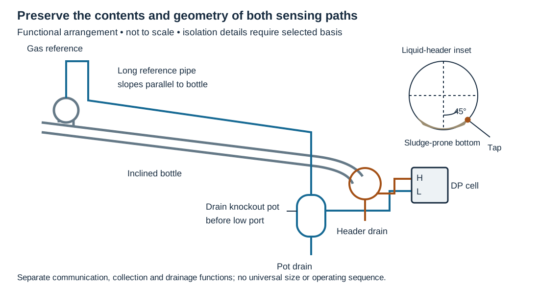
*Figure 8.3. A functional side view separates the long gas reference path, its drain pot and the liquid-side sensing connection. The header inset identifies the selected tap relative to bottom sludge. It is not to scale and gives no drain operating sequence or isolation specification. [Structured paths and geometry](assets/C22/reference-path.json).*
A compact vessel bridle offers a different tradeoff. Several instruments can share vessel connections, with suitable isolation and independent support for a heavy assembly. This may reduce penetrations and simplify removal, but it introduces a shared communicating path: a closed or obstructed root can affect several readings at once.
The selected slug-catcher arrangement excludes instrument bridles for its integrity basis. That exclusion belongs to this equipment route. It does not establish that every vessel bridle is unsuitable. Compare the actual service, sludge, density distribution, support loads, maintenance boundary and required independence before selecting either arrangement.
For this bounded static head model, write the pressure-head terms after the common gas pressure and all known fixed installation offsets have been removed:
$$
\Delta p_{\mathrm{head}}=g\left(\sum_i\rho_i h_i-\rho_r H_r\right),
\qquad
h_{\mathrm{ind}}=\frac{\Delta p_{\mathrm{head}}}{\rho_{\mathrm{cal}}g}.
$$
In these equations, $h_i$ is the vertical thickness of liquid layer $i$ above the liquid tap and $\rho_i$ is its density. The variable $H_r$ is the additional continuous vertical liquid head on the low-side reference path, and $\rho_r$ is that liquid's density. The calibration density is $\rho_{\mathrm{cal}}$. This simplified model assumes negligible gas-column head. Cancellation of the common gas pressure does not cancel hydrostatic gas head. Where that contribution is material, include the actual gas and liquid pressure-head integrals.
Heights are in m, densities in kg/m³, $g$ in m/s² and pressure difference in Pa. The minus sign applies because added low-side head reduces high-minus-low pressure.
The reference term describes a continuous column supplying that head to the low port. A shallow pool with gas communicating around it is not automatically a column of the same vertical height. Where the path contains several liquid or gas regions, use their actual pressure-head integrals and elevations.
Layering and added low-side liquid head can produce opposite indication errors. Partial cancellation at one condition does not validate the hookup or conversion. [Structured head/conversion method and units](assets/C22/differential-level.json).
## Select an observable level before choosing compensation
A single differential reading cannot generally resolve both total liquid depth and an unknown interface between liquids of different density. Several combinations of layer heights can produce the same head. Select the required output: total inventory, a particular liquid interface, liquid approaching a gas outlet or another defined process condition.
A long inclined bottle also has different elevations along its length. Thus selected taps and observed regions must use the same geometric datum as the intended output.
One compound-liquid approach uses multiple differential cells connected at predetermined heights. Its design premise includes knowing the maximum glycol level when locating those taps. The additional readings can constrain the inferred distribution, but retain the conditions that remain uncertain. Adding cells does not independently determine every unknown composition, density or blocked connection. Define how the selected combinations distinguish the required conditions and what observations would invalidate the conversion.
A different approach places gamma densitometers along the bottle. A horizontally oriented beam supplies a density-sensitive response through its selected chord, while several longitudinal positions observe different regions. This can provide information about denser liquid that a single total-head reading cannot separate. It still requires a selected calibration, geometric coverage, composition basis and operating range. A signal amplitude should not be credited as instant, unambiguous glycol identification for every mixture merely because one example proposes that interpretation.
Neither arrangement alone establishes a complete protective function. Its sensing, logic and final action retain the distinctions developed earlier.
*Table 8.1. Level arrangements, available information and premises.*
| Arrangement | Physical information available | Premise to retain | Consequence for the design |
| :--- | :--- | :--- | :--- |
| One differential cell | Integrated pressure head between the supplied references | Known path contents and usable density conversion | Unknown layering can resemble a change in total level |
| Multiple cells at selected heights | Several head relationships over different regions | Predetermined taps and a defined maximum interface range | More constraints, with remaining uncertainty and shared-path failures evaluated |
| Gamma measurements along a bottle | Density-sensitive response over selected chords and locations | Calibrated mixture response and actual coverage | Another observable, with its own uncertainty and installation requirements |
| Communicating local gauge or chamber | Local inventory in its connected region | Open, representative connections and readable range | Can corroborate a condition, but can also remain trapped or unrepresentative |
Implement the selected method with inspectable paths. Provide access to the actual tapping, pot, valves and device. Support the assembly without loading a small root or restraining equipment movement unintentionally. Preserve slope and low points after erection rather than rely on a line drawn at a nominal fall. Insulation or tracing may control phase changes where the service basis supports it, while changing heat input can alter fluid density or temperature. The thermal treatment and the measurement basis need to agree through normal operation, standby, startup and shutdown.
Verification should separate several questions. Does the cell respond to a known differential input? Are the process and reference paths in their selected communicating state? Does the conversion represent the current liquid distribution and density? Can the receiver and selected control action use that output? A satisfactory answer to the first cannot substitute for the others.
Following maintenance or cleaning, restore the specified path contents, connections, mode and reference condition through [readiness](#chapter-c18) and [intervention](#chapter-c20). Investigate path blockage, condensate accumulation, composition and actual inventory before adjusting zero or treating a drifting reading as proof of a process change.
## A control valve is an adjustable flow path with a selected action
A control valve throttles through its selected body and internal arrangement. An actuator moves the controlling member. Globe forms are common in the source-described arrangements, while ball, butterfly and other forms can serve particular duties. The selected flow direction, body, actuator and travel must be understood together. [Hardware and joints](#chapter-c03) develops their component behavior. This chapter connects that hardware to the sensing and control function.
An actuator may respond to pneumatic, electrical, hydraulic or other selected signals. A handwheel or handjack can provide a specified manual action. Those are different operating modes, not evidence that every signal loss results in the same valve position. Establish the actual action and failure or standby state for the selected service. Keep protective requirements with their governing basis.
Thermal and mechanical details affect the installed envelope. A selected cooling extension or fins can separate hot body conditions from the actuator, increasing height and changing clearance. A horizontally oriented assembly can introduce support and lubrication issues different from the usual vertical arrangement. Use the actual supplier configuration. Do not turn a historical temperature threshold or example actuator clearance into a universal rule.
Pressure and flow direction matter at the body. An angle arrangement or special-duty valve can have a selected side/bottom connection and flow path. The certified outline and service information establish that path. A control signal that moves the actuator does not prove that a wrongly connected valve provides the intended process function.
Control location should serve both information and action. An operator manually regulating vessel level needs the relevant indication visible from the operating position. A remote function needs the selected transmission and receiving interfaces. Shorter connection lengths can be useful, but are not the only criterion: process representativeness, access, signal arrangement and the actual equipment envelope must remain coherent.
## Stations provide operating modes, not automatic equivalence
A control-valve station can combine the control valve with upstream/downstream blocks, a bypass and selected drains. Its purpose can include continued operation while the control valve is being serviced. The station is therefore more than an arrangement of equal-pressure-rated valves. It creates different fluid paths and intervention states.
In normal automatic operation, the selected control path carries flow under its sensing and actuator arrangement. In a manual-bypass mode, flow can use another valve and path while the control valve is out of service. The operator needs the appropriate indication and means of adjustment. That mode need not preserve the automatic response, accuracy or protective functions of the normal arrangement. A bypass valve is not an automatic substitute for the controller.
When the control valve is removed, its isolation, trapped contents, opening and remaining pipe support need the applicable work procedure. The presence of two blocks on a drawing is not by itself proof of positive isolation for every service. [Special services](#chapter-c13), [maintenance](#chapter-c19) and [intervention](#chapter-c20) establish their required boundaries, while [supports](#chapter-c10) examines the partly dismantled assembly.
Valve and actuator removal should be physically possible. A flanged valve, a ring-joint connection and a screwed or socket-welded arrangement can need different break-out geometry. A removable elbow or the selected unions/spools may provide the required path. The body, actuator, handwheel, flanges and nearby vertical branches all occupy space. A station that can be bolted in place but cannot release its valve has not met its maintenance purpose.
Steam stations add condensate and temperature conditions. Their block, drain and support arrangements may differ from an ordinary liquid station. Coordinate the selected service rather than copy a universal station template. Likewise, a manual-handwheel arrangement and a station with a bypass can be alternatives rather than mandatory simultaneous hardware. Describe the actual selected configuration and the conditions under which each mode is used.
## Locate the complete instrument and the work it needs
Instrument location must satisfy sensing conditions and practical access. The P&ID identifies a function and connection. The instrument information supplies the dimensions, range, mounting and selected hookup. Coordinate these with vessel internals, piping, structures and the operator's task. A connection point alone is not the complete installed object.
Readability requires the intended line of sight and viewing side. Orientation, elevation and a swivel or fixed head can change whether a gauge is usable. Vessel level gauges can need their readable range aligned with the selected operating levels. A local flow or temperature indication used while adjusting a valve should be visible from that work position. It should not require viewing around another line or from a different platform.
Removal needs a path for the inserted or housed element. Thermowells, probes, level assemblies, valve actuators and panels can each require a different envelope. Do not use the space around a bare coupling as evidence that the assembly can be installed or serviced. [Spatial and work envelopes](#chapter-c04) supplies the common method, while this chapter supplies the particular instrument and signal requirements.
Mechanical environment also affects a reading and its boundary. A transmitter mounted on a vibrating structure can load its small connections and lose function. Thermowells and small-bore instrument branches have their own mechanical susceptibility. Mounting and support should preserve the sensing path and actual connection requirements without creating another thermal or vibration problem. [Mechanical analysis](#chapter-c09) and [supports](#chapter-c10) develop the evaluation.
Access categories differ with service and task. A portable means may be suitable for a particular meter inspection, while frequent operating action or a heavy actuator needs a different arrangement. Choose from the adopted task/access basis and actual equipment. A historical list saying an item needs no permanent access does not establish that every future maintenance job is achievable.
## Restore the function after testing or maintenance
Instrumentation can be installed, isolated, bypassed or partly removed while the main line is tested or maintained. A test boundary and pressure state can differ from normal service, and the sensing devices may need their specified treatment. [Verification and readiness](#chapter-c18) coordinates these changes. A successful test of the main line does not prove the final measurement or control state.
Restoration should identify which connections and communicating paths must be open or reassembled, which temporary conditions are removed, and which operating mode is intended. A valve left isolated can make a level cage or pressure indication represent a trapped condition. A bypass left in another position can change the controller's authority over flow. Verify the actual function rather than count installed tags.
Check the process connection, sensing mechanism, signal/receiving function and final element against the selected basis. Preserve calibration/range and fluid/reference information, confirmed mounting and removal clearances, action/direction and remaining limitations. These records allow later observations or service changes to reopen the right part of the chain through [engineering continuity](#chapter-c21). They are evidence of the actual state, not a second source of engineering truth detached from it.
# Chapter 9 — Pressure design, relief and depressurization
## Start with what can pressurize the system
Pressure design and protection must cover the same source connections and isolated volumes in each relevant configuration.
The starting point is the pressure sources and the paths between them. Sources include wells, pumps and compressors, controlled vessels, connected high-pressure systems, elevation head, heating of retained fluid and process changes. Operating, blocked-in, startup, shutdown, test and emergency-isolation states can connect or separate these sources differently. A line number identifies information. It does not prove that every volume with that identity remains connected to one protective device.
For each state, establish fluid and phase, pressure-generating equipment, valve lineup, inventories and heat sources, and receiving paths.
A centrifugal pump’s discharge pressure depends on its selected curve, speed or impeller, suction pressure and fluid conditions. A blocked discharge can expose the connected piping to shutoff pressure. Continued blocked operation can add heating or phase-change effects that a cold deadhead calculation does not describe. A positive-displacement source requires a different evaluation. Stopping downstream flow does not establish a benign source limit.
High pressure can also arrive from another system. A failed control element or an exchanger tube failure can connect a lower-pressure boundary to a stronger source. A check valve can affect reverse flow and isolate a pressure-relief route. Any credit for its operation belongs to the adopted scenario and reliability basis. The physical presence of a check valve does not prove that every reverse-flow or trapped-pressure condition is prevented.
Maximum pressure need not occur at the inlet. In a liquid pipeline descending from an elevated source, hydrostatic head can increase downstream pressure while friction decreases it. The governing location can change with flow and density. The complete operating range must be examined, including low or zero flow where relevant. [The engineering basis](#chapter-c01) supplies the service and system boundaries. [Rotating equipment](#chapter-c05) and [Other equipment](#chapter-c06) develop the source behavior.
## Keep pressure quantities attached to their conditions
Operating pressure describes a defined operating condition or range. Maximum operating pressure is the greatest pressure under the adopted operating basis. It may differ along the system. An upset case evaluates a specified departure or failure configuration. Design pressure is an input to the containment design at its associated temperature.
A component’s pressure-temperature rating and an equipment maximum allowable working pressure describe permitted capability under their respective bases. Relief set pressure describes an activation setting. The pressure required to pass the full relieving rate can be higher.
These quantities are related but are not interchangeable. A pressure margin chosen to avoid nuisance relief does not increase the component’s allowable pressure. A high flange rating does not prove that calculated pipe wall, gasket, valve trim or connected equipment has the same capability. A test pressure belongs to a temporary boundary and test condition. It does not establish a new operating rating. [Materials and classes](#chapter-c02) and [Pressure testing and readiness](#chapter-c18) carry those distinctions into selection and proof.
Pressure and temperature must be paired by credible state. The highest operating pressure may occur at a lower temperature than the highest operating temperature. Both combinations matter. One unrelated maximum cannot be assumed to describe every case. Depressurization can produce a cold condition whose material and component suitability differs from normal operation. Metal temperature can differ from bulk fluid temperature, particularly during transient exposure.
The pressure reference must be stated. Gauge pressure is measured relative to the stated surrounding pressure. Absolute pressure is measured from vacuum. Their relationship is $P_{abs}=P_g+P_{atm}$ when the gauge reference is the local atmosphere.
Gas-property and phase calculations need the pressure basis required by their method.
Internal pressure containment and external-pressure stability are separate evaluations. A cooled or drained isolated volume can experience vacuum. A jacket test can pressurize the outside of a core pipe. Wall adequate for one internal-pressure calculation does not establish resistance to collapse. [Jacketed assemblies](#chapter-c03) and [Nonmetallic collapse behavior](#chapter-c02) explain examples of that distinction.
## Straight-pipe wall calculation and limits
The following historical ASME B31.3 (1984) procedure evaluates straight-pipe pressure wall. It does not claim compliance with a current edition. Its factors and limits must not be transferred to a pipeline method or another material system. It evaluates pressure wall for its stated internal-pressure case. Other mechanical and stability evaluations remain necessary.
The method uses the following equations:
$$t_p=\frac{PD_o}{2(SE+PY)},\qquad t_m=t_p+c.$$
In these equations, $P$ is internal design gauge pressure for an atmospheric exterior, and $D_o$ is pipe outside diameter. $t_p$ is pressure design thickness. $S$ is the basic allowable stress at the relevant temperature. $E$ is the product quality factor, and $Y$ is the method’s material/temperature coefficient.
$c$ includes the applicable mechanical and corrosion/erosion allowances. $t_m$ is the required minimum wall before selecting nominal wall. $E$ and $Y$ are dimensionless.
For consistent units:
- Use the same pressure units for $P$ and $S$.
- Use the same length units for $D_o$, $t_p$, $t_m$ and $c$.
The historical method is bounded by $t_p
## Pipeline factors and component ratings follow different routes
Similar pressure formulas do not have interchangeable factors. The historical liquid-pipeline comparison uses $t_p=PD_o/(2S_{pipe})$. That pipeline method’s material and design-factor basis establishes the allowable quantity $S_{pipe}$. Gas-pipeline methods use yield-strength, location/design, joint and temperature factors with their own definitions. The process-piping $S$ and $E$ above cannot simply be inserted into those expressions. [Pipeline and offshore interfaces](#chapter-c11) establishes the system/code boundary.
This distinction can change the calculated rating of the same dimensional pipe. A pipeline factor applied to specified minimum yield strength and a process-piping allowable stress at temperature represent different criteria. A favorable numerical result from the wrong route does not establish additional capacity. A historical comparison must retain the applicable product, construction, temperature and location conditions. An application must use the adopted governing edition.
Flanges and valves commonly use pressure-temperature rating tables by standard, material group and class. Those tables provide a separate evaluation from pipe wall.
Use the actual material and temperature row to verify required pressure and component-specific limits.
Gasket, bolting, trim and proprietary connector conditions can impose narrower capability than the body designation suggests. A class designation is not a pressure expressed in psi or MPa.
A class built around a full flange envelope differs from a line with approved wall calculated for narrower actual conditions. Changes therefore have different consequences for the two cases. Raising the operating pressure toward the flange rating can invalidate the latter’s pipe-wall basis. Spare rating is a component characteristic. It is not an unexamined reserve for the whole installation.
## Evaluate the cause before selecting the protection
A relieving case identifies the source, protected volume and rate or transient that the protection must handle. Blocked flow, failed control, heat input, fire, tube failure, composition change and loss of fluid removal can govern differently. Cases should preserve how failures affect adjacent equipment and whether common utilities or controls create common-mode loads. An adopted single-event criterion is a scenario-selection rule. It does not erase dependent consequences of that event.
A blocked-in liquid can expand as its temperature rises. The fluid’s limited compressibility and the boundary’s compliance determine the pressure response. A small discharge may relieve thermal expansion. This does not establish capacity for continued inflow from a pump or a high-pressure source. Conversely, a relief device sized for a large inflow still needs a suitable setpoint and flow path for the volume that can become isolated.
A fire case can heat inventory and weaken a boundary. Containment and protection therefore need the relevant material/temperature and inventory basis. Loss of cooling or continued reaction can produce other rate and phase conditions. An exchanger failure can connect a high-pressure side to a lower-pressure side. Equal design pressures can remove a particular pressure-transfer contingency. They do not remove every heat-input, blocked-in or fire case.
The table identifies the questions that distinguish these evaluations. It assigns no design pressures or universal relief rates.
*Table 9.1. Pressure causes, demands and protection choices.*
| Cause and configuration | What determines the demand | Consequence for the choice |
| --- | --- | --- |
| Pump discharge blocked | Selected source curve, suction pressure, fluid and continued heating | Source-limit sufficiency versus relief; deadhead alone may not cover heated upset |
| High-pressure source through failed control | Available source flow/pressure and intervening restrictions | Containment, reliable source isolation or relief for the actual transfer |
| Liquid trapped between closures | Inventory, heating, compressibility and communicating path | Thermal protection of each isolated pocket |
| Exchanger internal failure | Pressure difference, phase and transfer through the failed path | Lower-pressure side and its connected protection assessed together |
| Fire or loss of heat removal | Heat input, inventory, phase, boundary temperature and scenario | Relieving load and/or emergency depressurization with receiving-system capacity |
| Rapid flow change | Fluid/system dynamics, closure/startup sequence and wave travel | Transient evaluation and surge-control measures; steady relief adequacy alone insufficient |
## Conditions for source sufficiency, relief and instrumented isolation
Designing the boundary for the maximum credible source pressure can remove the need for a particular overpressure device. This requires the full scenario basis to demonstrate that overpressure cannot occur. A selected centrifugal pump with a bounded maximum head may offer this route for a suitable system. The review must include suction pressure, the permitted pump configuration and the other pressure sources. Changing impeller, speed, source connection or valve arrangement can invalidate the argument.
Inherent containment sufficiency and reliance on active protection have different operation and maintenance demands. A pipeline procedure may favor source/design matching where its additional whole-life cost is minor. A process procedure may restrict protection by mechanical design to particular acceptable systems where mechanical relief is infeasible. Those adopted restrictions must remain with the selection. The engineering advantage of fewer protective devices does not grant an exception to a governing requirement.
Mechanical relief releases fluid at a rate sufficient to keep the protected condition within its permitted limit. Spring-loaded, balanced-bellows, pilot-operated and other relief arrangements have different backpressure and operating characteristics. The device, inlet, outlet and receiving system act together.
A rupture disc provides a different one-shot response. After rupture, it requires replacement and can leave the inventory communicating with the discharge system. Where frequent surge is expected, that consequence can make the disc an unsuitable substitute. Its capacity and upstream/downstream arrangement remain part of the design.
Instrumented pressure protection detects a condition and closes an isolation path before unacceptable pressure develops. Its integrity depends on sensing, response, final elements, independence and maintained reliability, under the permitted code and regulatory basis. It can be useful where discharge is impractical or would exceed receiving capacity. Ordinary operating pressure control does not automatically provide that protective function.
[Instrumentation, measurement and control](#chapter-c22) develops the sensing and control interfaces. The pressure evaluation must establish the required protective demand and response. [Operating functional integrity](#c19-functional-integrity) carries verification that the complete required protective function remains effective in the actual operating boundary.
A shared relief device can protect interconnected equipment only under two conditions. Every protected part must have a suitable communicating path, and the device must handle the required combined demand. A control or shutdown valve, filter, check valve or isolation arrangement can interrupt that path. Equal design pressure alone is not sufficient. The review must cover actual configurations in which the device may be unavailable or the volume separated, including maintenance.
## Set pressure and full-rate discharge belong to one system
Set pressure, pressure accumulation needed for capacity, reseating behavior, operating control and alarm settings form a coordinated pressure basis. Adequate separation between operating fluctuations and protective activation can reduce nuisance cycling and damage to seals. That separation must also leave full-rate protection within the applicable allowable condition. A percentage margin from one project cannot establish this relationship for every fluid, equipment type or governing standard.
Pressure loss between the protected volume and relief inlet affects the operating condition, as does backpressure in the discharge system. Superimposed backpressure exists in the receiving system before this device discharges. Built-up backpressure arises as discharge flows through it. Device selection and capacity corrections need those conditions, the relieving fluid and phase. Sizing a line only by the relief outlet’s nominal connection does not establish hydraulic performance or mechanical adequacy.
Disposal is part of protection. Flammable or toxic streams can require a closed collection system, liquid separation and flare or another specified destination. A harmless compressed-air discharge and a nitrogen discharge have different personnel hazards. An otherwise safe pressure release can create an asphyxiation or reaction-force exposure. Relief liquids returned to a tank must be compatible with its inventory, capacity and pressure condition. Atmospheric discharge demands its own exposure, noise and dispersion evaluation.
Collection capacity must address the cases that act together. A common utility failure or emergency depressurization can impose several loads at once. Simply selecting the largest individual valve is insufficient. Staging can change peak load and backpressure, but also the time required to depressurize each system.
The evaluation also needs inlet/outlet drainage, condensate or liquid collection, tracing where required, reaction loads, supports and maintenance access. [Mechanical analysis](#chapter-c09) and [Support selection](#chapter-c10) develop the associated load paths.
## Surge and thermal pressure call for their own response
Rapid changes in fluid velocity produce transient pressure changes. Valve closure, pump startup or shutdown and source isolation can therefore govern a condition that a steady-flow calculation misses. The transient must be estimated early enough to influence piping capability, valve actuation and receiving arrangements. Control of the rate of velocity change, sufficient containment margin and suitably located surge-relief or gas-cushioned arrangements address different parts of the event.
A slower closure can reduce surge in an appropriate system. However, closure speed cannot be changed independently of an emergency protective duty. An adopted pipeline procedure specifically separates instrumented protective shutoff from surge-control operation. A surge receiver also has to be available to accept the released fluid when demanded. A nominal tank connection does not establish readiness. Operating procedures should reduce avoidable surge even where protection is installed.
Thermal relief responds to heating of a trapped inventory. Isolation valves, check valves, equipment and temporary boundaries can create pockets that need identification. The release route must reach the retained fluid and lead to a suitable destination. Under the adopted basis, coordinating thermal protection settings with the main protective system can avoid unwanted activation of larger equipment. Avoiding unnecessary block-in and heating remains useful operating practice. A thermal valve is not a reason to ignore the condition.
## Depressurization is a transition of an isolated inventory
Relief controls a specified overpressure demand. Emergency depressurization reduces the pressure and inventory of an isolated system for a defined incident duty. These functions can discharge to the same collection system while needing different sizing, initiation and operating assumptions.
The depressurization basis needs the segment that becomes isolated, its contents and pressure-temperature condition, and every communicating volume within it. Check valves can retain pressure on one side after another volume is blown down. The blowdown route must address the intended isolated segment, with the isolation and initiation sequence coordinated. The diagram illustrates two distinct discharge paths. It does not specify a universal arrangement or valve action.

*Figure 9.1. Conceptual arrangement of one pressure source and a protected inventory. A relief path serves the connected protected boundary. A separately initiated blowdown path depressurizes the defined isolated inventory. Required capacities, valve actions, timings and receiving-system arrangement are unspecified.*
Pressure reduction can cool the fluid and metal and generate vapor from retained liquid. It can produce hydrate concerns, high velocity, erosion, noise and reaction forces. A blowdown valve and downstream piping must serve those changing conditions. A restriction or diffuser can control some effects but changes the achievable rate and pressure distribution. Material suitability must include the minimum relevant temperature. [Material selection](#chapter-c02) cannot remain tied solely to the hot operating state.
The required depressurization time and final pressure belong to the project incident and equipment basis. A particular philosophy can specify a target such as 100 psig or half design pressure, whichever is lower, within 15 minutes. That is a conditional project criterion, not a universal survivability result. The actual transient, material temperatures, equipment limits and flare duty must be evaluated against the chosen requirement.
A compressor or other sensitive equipment may impose a maximum rate of pressure reduction. If the incident target and equipment limit conflict, substantiated equipment mitigation or a smaller isolated segment needs investigation before a slower result is accepted. Moving or adding isolation close to the sensitive equipment can reduce the volume subject to its rate restriction. This changes system architecture, operation and maintenance. It therefore requires more than adjusting a blowdown orifice.
Facility blowdown can create backpressure that prevents safe discharge of low-pressure systems or causes backflow. Staged blowdown and segregated receiving arrangements can address that interaction. They have their own timing and capacity consequences. High- and low-pressure collection should reflect the evaluated loads, rather than merely the names of the connected systems.
Blowing down vapor does not necessarily remove liquid. A philosophy may leave liquid contained while handling vapor evolved from it and the fire case. Another duty may require separate liquid deinventory. The basis must state which is intended. “Depressurized” does not prove that a system is empty, chemically clean or ready to open. [Operation](#chapter-c19) and [Intervention](#chapter-c20) develop those subsequent conditions.
### Shutdown commands and actual inventory state
Equipment shutdown, isolation and blowdown are distinct demanded actions. Their physical result depends on valve closure and communicating paths; shutdown can leave pressurized inventory.
One adopted project philosophy illustrates the distinction. Its operator emergency-shutdown command demands isolation and shutdown but does not automatically initiate blowdown. The operator has a separate means to request blowdown of the affected areas. Confirmed fire or gas initiates emergency shutdown and automatic blowdown under that philosophy. These event/action relationships belong to a selected basis. They are not competing universal definitions of emergency shutdown.
The same basis distinguishes process shutdown from total-plant shutdown. Process shutdown retains utilities and electrical generation while stopping the process. Neither that command nor the total-plant command automatically initiates blowdown.
In this adopted basis, total-plant shutdown normally demands stopping process systems, utilities and power generation, subject to specified essential-equipment exceptions. Essential emergency equipment can also remain energized under its specified exceptions. Examples include firewater or water-mist pumps, standby generation and instrument air. The word “total” cannot substitute for the actual list of required and retained functions. The defined incident state must establish which consumers, energy sources and supplies must stop or remain available.
Coordinate these actions with the segment actually isolated, retained pockets, the blowdown route, receiving-system capacity and surviving utilities. Confirm the required pressure endpoint and any required liquid removal before relying on the resulting state. These event/action relationships do not prescribe another plant’s sequence, valve fail position or reset permission. [Sensing and protective action](#chapter-c22) develops the protective logic; [functional integrity](#c19-functional-integrity) covers verification in the actual boundary.
## Atmospheric tanks need pressure and vacuum paths
A low-pressure tank can be damaged by filling, withdrawal or heat when its breathing path is inadequate. Inflow displaces vapor. Outflow requires replacement gas or a vacuum-protection path. A blanketing and vapor-recovery system therefore interacts with the maximum filling and withdrawal duties. A permanently open vent used for one nonhazardous service differs from the closed arrangement of a hazardous inventory.
Pressure relief, vacuum breaking and emergency venting have different initiating conditions. A normal breathing path does not automatically establish fire vent capacity. A relief-only device does not establish vacuum protection. The receiving destination, overflow possibility, blanketing supply and maintenance isolation must be considered with the tank type. [Storage](#chapter-c06) develops the containment and equipment account. This chapter preserves the pressure-protection interface.
## Keep the protective basis alive through test, operation and change
The protection record needs the cases, source capabilities, communicating boundaries, device settings/capacity basis and receiving-system assumptions. Testing a relief device confirms selected device properties. It does not establish that the installed inlet/outlet path is unobstructed or that every intended volume remains connected. Inspection, proof testing and replacement need the actual component identity and service history. Statutory or adopted intervals remain applicable requirements.
Maintenance isolation can remove a relief route. Temporary test blinds or closed valves can create a new pocket. Before introducing pressure, establish what protects the resulting configuration. Reinstatement must restore intended communication and remove temporary restrictions under the readiness procedure. The pressure chain runs from [defined conditions](#chapter-c01) through this chapter’s containment/protection decisions to [verified test and restoration](#chapter-c18).
Change can reopen the original protection choice. A larger impeller, higher source pressure, new upstream connection, altered control response, replaced valve, hotter cleaning method or larger isolated volume changes the cases or capacity. Before relying on the old setting, reevaluate the affected boundary and neighboring receiving system. The useful record explains why the protection works in its defined states. A future change can then identify what has ceased to be true.
# Chapter 10 — Flexibility, loads and vibration
## Evaluate how the connected system responds
Weight support, pressure containment and displacement accommodation can compete: an offset can reduce thermal reactions while increasing weight deflection; a vibration restraint can increase displacement loads. Analyze the connected system.
The system description begins with pipe and component dimensions, materials, temperatures, contents, terminal connections and the support/restraint arrangement. Equipment can move. Structures can settle. Sliding contacts can resist movement or lose contact. The model represents those relationships.
It does not prove that the installed line has the represented gaps, freedoms, spring settings or boundary stiffness.
Before assembling load cases, define the physical states. An operating state combines contents, conditions, configuration and contacts. A test state can have heavier contents, different boundaries and temporary restrictions. A maintenance state can remove a component or terminal load path.
A load case evaluates a selected combination of inputs. Several cases can be needed to understand one state or the displacement range between states. [The engineering basis](#chapter-c01) and [Support and restraint selection](#chapter-c10) carry the corresponding system and installed-load-path account.
## Separate sustained demand, displacement and dynamic forcing
Weight includes pipe, fittings, valves and operators, lining, insulation and contents. Test liquid belongs in the inventory even when normal contents are vapor. Concentrated mass at a valve can govern a span or nozzle moment differently from uniform weight. Snow and ice enter where required by the project. Pressure contributes to containment and mechanical loading. End thrust and pressure reactions need evaluation where the configuration produces them.
Sustained demand follows the load path available in the relevant state. A support that lifts clear of the pipe cannot continue carrying its assumed vertical reaction. A line can be acceptable while resting on every cold support. Its lifted hot configuration can have a different weight-stress problem. Separating thermal and weight calculations does not permit an impossible weight-support arrangement to remain in the model.
Thermal expansion, contraction, terminal motion and settlement impose displacement. Their effects depend on relative movement and restraint. Different demands arise from a uniform temperature rise between fixed points, a hot header with a cold standby branch, or an expanding vessel connected to a cooler line. Startup, shutdown, steam-out, decoking, regeneration and depressurization can produce other temperature combinations or ranges. Normal operation alone does not represent these. More than one analysis case may be needed to establish the relevant displacement stress range.
Wind, seismic effects and other occasional demands follow their adopted site and service basis. A particular project’s exemption from seismic calculation cannot become a general rule. Relief discharge, water hammer, slugging, machinery forces and pressure pulsation require their appropriate dynamic or transient treatment. They should not appear as unexplained additions to a normal static case.
*Table 10.1. Physical states and mechanical evaluation consequences.*
| Physical state or transition | Inputs that change | Evaluation consequence |
| --- | --- | --- |
| Empty installation | Incomplete insulation, disconnected equipment, locked springs or temporary supports | Construction load path and fit-up may differ from the final operating model |
| Liquid test | Fluid weight, temporary blinds, pressure and retained locks | Test loads, temporary supports and terminal boundaries need the actual test configuration |
| Hot operation | Metal temperature, sliding friction, lift-off and spring travel | Sustained support path and displacement reactions must remain physically possible |
| Cold standby branch on a hot header | Unequal temperatures and terminal conditions | Relative branch/header movement can govern despite a satisfactory uniform-hot case |
| Steam-out or depressurization | Temperature extremes, changing phase/pressure and equipment movement | Review displacement range, material limits and connected equipment conditions |
| Maintenance or change | Removed valve/spool, altered mass, new restraint or movement | Reevaluate affected load paths and restore the intended configuration |
### Establish the metal-temperature range before calculating growth
The cold endpoint is not always the installation temperature. The hot endpoint is not always the normal flowing condition. Sun can heat an idle line. A tracing or heating system can remain active after process flow stops. A vessel can be steamed while its connected line remains cooler. A dual-service line can experience both a hot fluid and a temperature below the winter ambient.
Establish the metal-temperature history and independently heated equipment, displacement interval and coincident pressure/contents.
One specifically adopted historical mechanical-analysis procedure illustrates this with a Celsius convention. It assumes a 50°C metal temperature from solar heating without flow and a −40°C winter endpoint. For a metal temperature above 50°C, it uses that temperature plus a 40°C interval. For a temperature between −40°C and 50°C, it uses a 90°C interval. Below −40°C, it uses 50°C minus the metal temperature.
These are conditional procedure temperatures; its paired Fahrenheit labels are rounded historical values. Use one consistent convention for absolute temperatures and intervals. A dual-service range can extend beyond these endpoints: use its full credible transition with applicable material growth data.
A real project must establish which endpoints and simultaneous equipment states are credible. A larger interval assembled from mutually impossible conditions is not automatically a better load case.
## Calculate thermal growth from a defined reference
Thermal-growth data describe the change in length over a temperature interval for the selected material. A table of total expansion from a reference temperature is not a constant coefficient per degree.
Suppose $g(T)$ is the tabulated growth, in inches, of a 100 ft reference length from a common reference temperature. The free growth of a straight length $L$ between temperatures $T_1$ and $T_2$ is:
$$\Delta L=\frac{L}{100\ \mathrm{ft}}\,[g(T_2)-g(T_1)].$$
Use $L$ in feet to obtain $\Delta L$ in inches for this table convention. The subtraction retains the common reference. Setting $g(T_1)=0$ is valid only when $T_1$ is that reference. Negative tabulated growth represents contraction below it. Free growth is a displacement tendency. The actual restrained system develops forces and moments while accommodating growth through deformation and permitted motion.
The selected historical data below use 70°F as their reference. They illustrate material differences for preliminary understanding, with the grouping stated. They do not supply current qualified material properties for every grade or validate the material’s suitability at those temperatures.
*Table 10.2. Bounded linear-growth reference values.*
| Temperature, °F | Carbon steel/C–Mo/low chrome through 3 Cr–Mo | 5 Cr–Mo through 9 Cr–Mo | Austenitic stainless, 18 Cr–8 Ni |
| --- | --- | --- | --- |
| 70 | 0.00 | 0.00 | 0.00 |
| 200 | 0.99 | 0.94 | 1.46 |
| 300 | 1.82 | 1.71 | 2.61 |
| 400 | 2.70 | 2.50 | 3.80 |
| 500 | 3.62 | 3.35 | 5.01 |
*Values are inches of linear growth per 100 ft between 70°F and the indicated temperature. Blank entries elsewhere in the underlying table are not zero properties.*
Do not multiply a total-growth table entry by temperature rise; that counts the interval twice.
Resolve growth in the relevant directions between terminals and restraints. Add equipment or structure movement with its direction and sign. A nozzle moving toward the pipe’s free-growth direction can reduce one relative displacement and increase another. Settlement is imposed relative movement, with its own origin and time history. It is not a thermal expansion coefficient. Layout methods based on a stationary anchor must be revised when the terminal actually moves.
## Offsets and loops turn growth into bending
A straight line between fixed ends has little geometric freedom to absorb axial growth. Bends, offsets and loops allow transverse legs to deform, reducing the reaction required to accommodate that growth. Their effect depends on the leg lengths, section stiffness, terminal constraints and component flexibility. A rigid valve or flange can shorten the effective absorbing length. An attachment near an elbow can reduce its assumed flexibility.
Choose a useful route before adding expansion devices. Direction changes required by the process arrangement can sometimes provide sufficient flexibility without a dedicated loop. A long header can distribute movement into flexible branches or direct growth from a selected fixed point. Those choices affect every connected branch and nozzle. A locally satisfactory offset therefore does not establish the entire header system.
Expansion joints provide another route when space or cost constrains pipe geometry. Bellows, sliding or other proprietary devices have particular movement, pressure-thrust, guide, anchor, fatigue and maintenance requirements. An axial joint can transfer pressure thrust to anchors. A flexible connector does not make that load disappear. If the adopted basis requires authorization for expansion joints, obtain it as part of selection. The device is not an ordinary substitute for an elbow.
The native figure defines the simple symmetric loop used in the next method. It shows geometric dimensions and anchor spacing. Weight supports, guides, bends and terminals still need their own design.
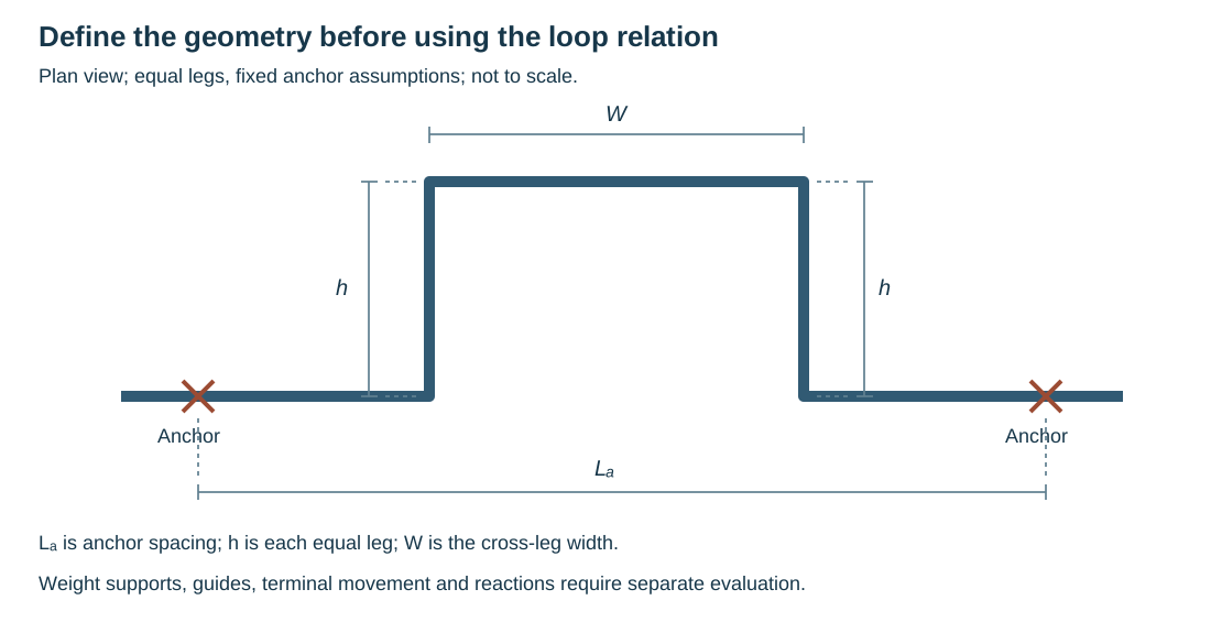
*Figure 10.1. Plan geometry with equal legs $h$, width $W$ and anchor spacing $L_a$. The anchors are fixed assumptions of this preliminary method, not recommendations for every routed line.*
### A preliminary loop calculation needs its unit convention
For the historical standard-weight carbon-steel loop layout method shown, one preliminary depth relation is:
$$h^2\geq0.0004D_oL_a\Delta T,$$
In this equation, $h$ and anchor spacing $L_a$ are in feet. Outside diameter $D_o$ is entered in inches, and temperature rise $\Delta T$ is in degrees Fahrenheit. The numerical constant embeds those units. It is not a dimensionless physical law that can be reused with millimeters, meters or degrees Celsius.
The same procedure applies a separate temperature-dependent minimum:
$$h\geq\frac{A D_o}{1.25},$$
In this equation, $D_o$ is again entered in inches to obtain $h$ in feet. $A$ is the tabulated carbon-steel factor for the design temperature, distinct from the temperature rise. The procedure gives a minimum width $W=0.5h$ and a preferred width $W=1.5h$. These are layout criteria for this method. They are not universal proportions or proof of acceptable anchor reactions.
The method’s standard-weight and material basis matters. A different section has different bending stiffness, and terminal motion can change the displacement to be absorbed. The historical quick-layout procedure supplies corrections for wall stiffness and anchor movement. Each correction requires its stated definition and geometry. Thicker pipe is not always mechanically better. It can increase the force needed to accommodate imposed movement.
L, Z and equal- or unequal-leg U configurations have different relations and leg checks, developed below. A numerical constant chosen for the symmetric loop cannot be assigned to any convenient offset. A fuller analysis needs the actual arrangement if route, component rigidity, support contact or terminal conditions differ materially from the simple method. Even a layout satisfying both loop checks still needs sustained-load, terminal-force/moment, pressure, local-detail and dynamic evaluations.
### Choose the relation for the actual offset
An L-shaped route absorbs growth primarily by bending its shorter transverse leg. A Z-shaped offset provides two parallel legs of unequal length connected by that transverse leg. Equal and unequal U shapes distribute deformation through different leg arrangements. Their historical layout relations therefore use different coefficients and additional geometric checks. The letter describing the shape is not permission to use the symmetric-loop relation for it.

*Figure 10.2. Schematics of fixed-end geometry, not to scale. In an unequal U, $h$ is the cross leg. In the equal U it labels each equal side leg. In the guided loop, $H$ and $W$ index the reaction/stress coefficients. Guides retain axial freedom. No weight-support or construction detail is specified.*
For these quick-layout relations, use the following unit convention:
- Enter $D_o$ in inches.
- Enter leg lengths in feet and temperature rise $\Delta T$ in °F.
The standard-weight carbon-steel basis discussed above remains applicable. The procedure’s diameter convention rounds outside diameter upward to the specified half-inch increment. $A$ still corresponds to design temperature, not rise.
Pressure, branch/equipment restraint and special thermal conditions belong to the initial basis. Austenitic stainless steel and aluminum cannot inherit this carbon-steel basis merely by changing their names.
The L relation is $h^2\geq0.0025D_oL\Delta T$, accompanied by $h\geq AD_o$. Its inverse maximum-long-leg expression is $L\leq400h^2/(D_o\Delta T)$.
A Z uses the same growth-depth and inverse-length relations, but its parallel legs $B$ and $C$ must also satisfy $B/C\geq4$, with $L=B+C$. Both the transverse leg $h$ and the longer leg $B$ are tested against $AD_o$.
Equal parallel legs would fail this particular ratio condition even if the transverse depth passed. An apparently similar offset can therefore require a different evaluation.
For an equal-leg U, the relation becomes $h^2\geq0.0016D_oL\Delta T$. Its inverse is $L\leq625h^2/(D_o\Delta T)$. The independent evaluation is $h\geq AD_o/1.25$. $L$ is its cross-span as shown, not the developed length around both legs.
The unequal U uses the difference between the parallel legs. One printed relation is $h^2\geq0.0021D_o(L_1-L_2)\Delta T$ for $L_1>L_2$. The further conditions are $h+L_2\geq AD_o$ and $L_1\geq AD_o$. The reported alternative $h\geq0.045\sqrt{D_o(L_1-L_2)\Delta T}$ is not exactly the square root of that coefficient: $0.045^2=0.002025$, not 0.0021.
The discrepancy between the two printed depth forms remains a local method limitation. Do not silently average them or claim justified equivalence for a marginal arrangement.
More complicated planar routes can be decomposed into the major direction and the relevant transverse absorbing legs. The described planar adaptation compares the required short leg with the square root of the sum of squares of its specified perpendicular leg lengths. The three-plane adaptation first establishes the signed separations in each global direction and identifies the largest governing direction. These are geometry-specific adaptations. Summing every developed pipe length into one fictitious absorbing leg loses both direction and restraint information.
Section stiffness and terminal motion also change the quick-layout result. When wall differs from the standard-weight basis, the procedure adjusts minimum leg by $I_{specified}/I_{standard}$. Where terminal expansion adds in that direction, it adjusts minimum leg by the ratio of total movement to pipe-leg movement. $I$ is the second moment of area, using equal length units in the ratio.
This is its stated correction, not a general scaling law for every bending problem. Signs and movement directions must be resolved before combining displacements. A beneficial terminal motion is not an unexplained reduction factor.
### Resolve route legs before selecting an absorbing length
Figure 10.3 separates three geometric accounts. In the planar route, the signed horizontal separation is $a+c+e$ and the vertical separation is $b-d+f$. The selected adaptation assumes the former is the major direction $L$. It compares the required transverse length with $\sqrt{b^2+d^2+f^2}$. The negative sign on d describes its direction between terminals, while its squared length remains positive in that particular transverse comparison. Replacing both quantities by the sum of all pipe lengths would lose the distinction.
In the three-plane route, the terminal separations are $X=a+e$, $Y=c+g$ and $Z=b-d+f$. Before applying the selected adaptation, identify the largest separation in the actual geometry. The drawn example assumes $X$ governs. For that assumed direction, the transverse legs are b, c, d, f and g. The procedure compares their summed lengths with the required short leg. That is a different construction from the planar root-sum-square comparison, not a choice of whichever produces the smaller required route.
Retain the standard-weight, material, diameter, temperature and unit limits of the preliminary method above, including its unresolved alternative coefficient differences. Geometry alone supplies no stress or nozzle acceptance.
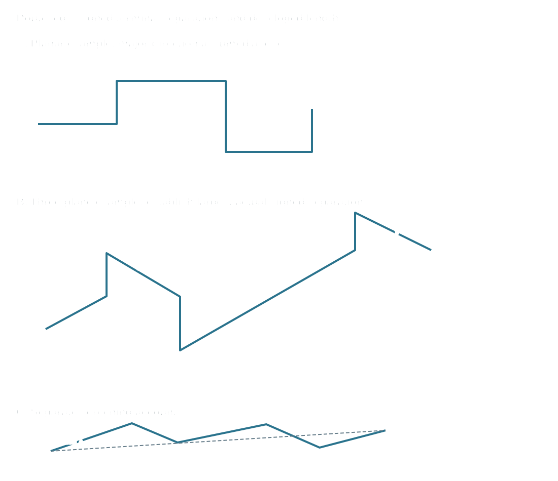
*Figure 10.3. Schematic leg identifiers and signed directions. The third panel distinguishes developed pipe length $L_d=\sum|l_i|$ from straight terminal separation $U=\sqrt{X^2+Y^2+Z^2}$. Neither is automatically the major-direction L or absorbing h used by an offset method. [Structured geometry](assets/C09/c09-route-direction-geometry.json) records the different accounts.*
The separate screening procedure uses developed length and straight anchor separation as different inputs. A routed line with many turns can have a large developed length while its anchors remain close. Terminal movements must still be combined in their actual directions. A scalar chord does not turn several directional movements into one pipe-leg expansion. Each method needs its appropriate geometry. The symbol L must not be transferred between the sketch, a span table and a screening inequality.
### A deliberate preset moves the cold and hot positions about a neutral datum
The neutral shape is the unstressed geometric datum for the illustrated L-route. Without a preset, the cold shape lies at that datum and heating moves the elbow in the expansion direction. A cold-spring preset deliberately positions the cold elbow on the opposite side. Heating then carries the elbow through the neutral position toward the hot position. Figure 10.4 distinguishes all four states. The specified amount, direction and fabrication sequence are part of the analyzed assembly, rather than an undocumented pull used to close a misaligned flange.
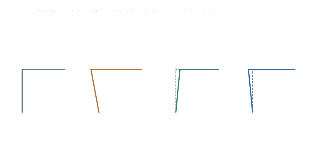
*Figure 10.4. Conceptual positions relative to the same neutral datum. In a hypothetical one-direction example with 3 in growth and a 1.5 in opposing preset, the cold and hot offsets are −1.5 and +1.5 in. Without preset, the hot offset is +3 in. The drawn deflections are exaggerated and do not calculate force reduction. [Structured state data](assets/C09/c09-cold-spring-positions.json) retain the signs and assumptions.*
The example redistributes cold/hot displacement about neutral. It does not reduce the thermal displacement range or establish a proportional reduction of every force, moment or stress. Actual supports, terminal movement, stiffness, installation tolerances and the authorized cold-spring treatment govern the result. A small prescribed amount can be lost within ordinary fabrication tolerance. When the analysis requires it, the drawing must specify an executable amount and hold tolerance.
Resolve any project prohibition or approval condition for cold spring at rotating equipment before specifying it. [Installation verification](#c10-installation-test) and [fit-up control](#c17-tolerances-fit) carry that intent into construction. Force fitting is not a substitute for the analyzed preset.
### Check what the loop sends to its anchors
Minimum layout depth answers whether the preliminary route has the prescribed geometric flexibility. It does not answer how much force each anchor receives or what maximum stress the loop develops. A separate guided-loop method addresses those questions for long-radius elbows and line sizes NPS 4 through 14. Expansion to be absorbed is limited to 10 in.
Its geometry includes equal loop legs $H$, width $W$, anchors outside the loop and guides on both straight approaches. The figure places each approach guide at least 40 pipe diameters from the associated loop bend. That historical layout condition is retained as stated. The diameter convention and actual guide detail must be established before applying it.
The relations are:
$$F=C\delta I_p,\qquad \sigma_{max}=K\delta D_o.$$
In these equations, $\delta$ is expansion to be absorbed in inches, not elastic modulus. $I_p$ is pipe second moment of area in in⁴. $D_o$ is outside diameter in inches. $C$ and $K$ are numerical coefficients indexed by $H$ and $W$ in feet.
In the method’s inch-pound convention, $F$ is force in lbf and stress is in psi. The corresponding coefficient dimensions are lbf/in⁵ for $C$ and psi/in² for $K$. The tabulated numbers retain these embedded units; SI dimensions cannot be inserted into them. The force is the stated loop force at each anchor. It is not a complete six-component equipment-nozzle load vector.
The coefficient grids are identified by their actual $C$ and $K$ headings and their $H/W$ dimensions. The design-temperature $A$ grid serves the earlier minimum-leg evaluations. It cannot supply either reaction coefficient. The selected exact entries below avoid interpolation and illustrate the distinction between height and width effects.
*Table 10.3. Conditional guided-loop reaction and stress coefficients.*
| $H$, ft | $W$, ft | $C$ for force | $K$ for maximum stress |
| --- | --- | --- | --- |
| 20 | 10 | 1.64 | 337 |
| 20 | 20 | 1.46 | 270 |
| 20 | 30 | 1.33 | 230 |
| 15 | 10 | 3.03 | 457 |
| 15 | 20 | 2.68 | 372 |
| 15 | 30 | 2.44 | 313 |
At fixed expansion and section, reducing loop height raises both demands in the displayed grid. Increasing width at fixed height lowers them, subject to the actual guides, weight support and available geometry.
These estimates do not establish allowable force, stress or fatigue life. The printed method does not provide a full derivation or every material/modulus, elbow or load-combination condition underlying its coefficient grids. The results are historical estimates within the displayed geometry/range. They require the applicable analysis and acceptance basis. Do not extrapolate to a different guide configuration or a table dimension outside its range.
A thicker wall can change $I_p$ and hence anchor force even when the same outside diameter is retained. The pipe-stress result must still be evaluated under its appropriate method and material basis. The existing equipment-load and model-contact account remains necessary alongside this useful preliminary calculation.
### Keep force and stress inversions on their separate chart bases
A two-straightedge nomograph can invert a chosen planning criterion. For a directional thermal movement and pipe section, it estimates the absorbing leg required by that chart. Figure 10.5 preserves two different constructions.
The pump chart first joins expansion in inches to an assumed nozzle-force criterion in lbf, intersecting the pivot line. It then joins that pivot point to a section ordinate. The vessel chart first joins expansion to a stress criterion in psi, then joins the pivot point to nominal diameter. Each second line crosses its own pipe-length scale in feet.
A force and a stress are different physical quantities. Neither chart’s criterion can be moved to the other’s axis or combined with another method’s allowable.

*Figure 10.5. Native reconstructed scales and two-line inversions within the recovered domains. The selected tick values retain original scale positions. Interpolation is logarithmic in the values between labeled ticks, while straightedge geometry is linear in chart coordinates. Source coordinates are graphic calibration, not pipe dimensions. [Scale data](assets/C09/c09-nomograph-data.json), [results](assets/C09/c09-nomograph-calculations.json) and [reproduction script](assets/C09/c09-nomograph-reproduce.py) preserve the bounded operation.*
The pump chart's nominal-diameter marks are for standard-weight pipe. For another wall basis, the procedure uses its moment-of-inertia scale, in in⁴, instead of the nominal-diameter scale. Establish actual section inertia in the chart's units before making that substitution. The vessel chart has no recovered inertia axis here. It does not inherit the pump’s wall adjustment by analogy.
Both procedures depend on the selected route and the perpendicular legs available to absorb each directional movement, including terminal growth, stiff valves/nozzles and supports. A three-plane drawing is not permission to sum all unsigned growth into one displacement.
For preliminary pump planning only, the historical steel-nozzle assumption is $F_p=\min(200d_n,2000)$ lbf. The cast-iron assumption is $F_p=\min(50d_n,500)$ lbf. Nominal nozzle size $d_n$ is in inches. These are author-selected planning criteria when published equipment data is unavailable. They are not code-defined or vendor-qualified loads.
The illustrative steel 10-in nozzle therefore gives 2,000 lbf. The line size used on the section axis can differ from the nozzle size used to select that force. The vessel example separately assumes 14,000 psi. It is not a complete vessel nozzle, shell or weld evaluation.
| Chart and declared inputs | Approximate reconstructed length | Graphical read band |
| --- | --- | --- |
| Pump: 0.713 in, 2,000 lbf, standard-weight nominal 12 in pipe | about 23 ft | about 21.5–24.5 ft |
| Pump: 0.506 in, 2,000 lbf, same pipe | about 20.5 ft | about 19–22 ft |
| Vessel: 0.179 in, 14,000 psi, nominal 30 in pipe | about 17 ft | about 16–18.5 ft |
| Vessel: hypothetical 0.5 in, 14,000 psi, same diameter | about 29 ft | about 27–31 ft |
The first three input pairs follow the historical exemplars. The outputs here are independent graphical reconstructions with coarse read bands. The last pair is a hypothetical movement sensitivity comparison. The bands describe chart-reading/calibration uncertainty, not an engineering safety factor or statistical confidence. No underlying exact nomograph equation has been inferred. The saved reproduction rejects inputs or length outputs outside its recovered scales.
Near a comparison boundary, obtain a qualified analytical result. Additional digits in the graphical estimate do not resolve the comparison.
The bounded pump data cover expansion 0.2–2 in, force 1,000–3,000 lbf, standard-weight nominal sizes 10–24 in or inertia 200–2,000 in⁴, and length outputs 10–50 ft. The bounded vessel data cover expansion 0.1–2 in, stress 10,000–20,000 psi, nominal sizes 12–36 in and length outputs 10–70 ft. These are recovered graphical domains, not applicability limits that make every pipe/material in them acceptable. Each input must remain on its selected historical model and the actual engineering basis must supply current acceptance criteria.
The historical examples also contain two consequential ambiguities. One vessel step calls its east-west leg 18 ft while multiplying 25 ft. Its route drawing labels 25 ft. Those alternatives give different movements, so the stated example's result is not certified by silently selecting one.
Separately, a vertical-growth step multiplies feet by an inches-per-foot growth coefficient and prints 0.828 ft. The operation produces inches under that unit convention. The printed foot label cannot be adopted as a displacement without resolving the inconsistency. Preserve the entered length, unit and resulting direction together before using the chart. The native inversion data do not claim verification of those ambiguous example conclusions.
After a leg change, recalculate movements in all affected directions and the reactions at equipment and supports. Making one chart comparison favorable can increase another terminal's demand or alter access and weight support. Use this inversion as a bounded planning estimate with its declared criterion. The actual flexibility, nozzle/shell, attachment and structure assessment closes the design.
## Screening identifies a need for deeper evaluation
A screening method is useful when its assumptions match the system and the result is treated as a bounded decision aid. Experienced comparison with a successful similar installation, a simple hand method and a detailed model have different evidential strength. Similar appearance is insufficient when temperature range, restraints, product stiffness or equipment limits differ.
One historical flexibility screen is:
$$q=\frac{D_n\Delta}{(L_d-U)^2}\leq0.03,$$
In this inequality, $D_n$ is nominal pipe size entered in inches. $\Delta$ is displacement to be absorbed entered in inches. $L_d$ is developed line-axis length in feet, and $U$ is the straight distance between anchors in feet.
This $D_n$ differs from outside diameter in the loop method. This $L_d$ differs from the loop’s anchor spacing. The threshold embeds the specified inch/foot convention. It is not a dimensionless acceptance value transferable to another unit system.
Source-specific analysis criteria can require formal evaluation independently of this screen. One adopted metallic-piping basis explicitly includes:
- Load-sensitive equipment
- Fired-heater and turbine lines
- Reciprocating equipment and relief systems
- Proprietary expansion devices
- Significant differential settlement
- Severe cyclic/vibrating service
- Jacketed piping and plastic-lined systems
Another uses different size and temperature triggers. For example, their centrifugal-pump triggers can be NPS 3 and larger under one basis and NPS 4 and larger horizontal-pump piping under another. Retain the applicable basis and its exceptions. Do not average the thresholds or use a favorable screen to evade a mandatory category.
### Prepare signed relative movement before taking a resultant
The displacement supplied to a preliminary screen should be the movement that the connected pipe must accommodate. To prepare the displacement:
- Choose an origin and axes.
- Retain the signs of pipe growth and terminal movements.
- Before forming a magnitude, combine compatible components.
Taking the absolute value of each contribution too early can turn a movement that offsets another into an artificial addition. Conversely, adding a terminal motion as one unsigned scalar can hide an increased demand in a different direction.
A relative-displacement vector also has a reference condition. Equipment growth measured from a cold support datum must not be combined with pipe growth measured from a different, unexplained origin. Before using nozzle movement, resolve a segmented vessel temperature profile from its actual support reference. A nozzle’s elevation alone does not establish its growth. Rotation and settlement can require additional boundary inputs beyond this simple translation.
## Contacts and friction make the model state dependent
A resting support carries weight only while contact exists. A guide acts after its relevant gap closes. A stop limits selected travel. A spring changes load with travel according to its design. Rod hangers can swing and introduce horizontal reactions as their geometry changes. The pipe and support structure can both move, so a restraint relative to structure is not necessarily a fixed point in global space.
Sliding contact resists motion through friction. Its effect can redistribute force between supports and equipment, change which point moves and alter the path between cold and hot conditions. The model should reflect the adopted friction basis and actual surface/load arrangement. A frictionless assumption is a particular idealization, not the default meaning of “support.” Likewise, a perfectly rigid anchor can be an inappropriate representation of a flexible bracket, baseplate or structure.
One adopted analysis basis permits an assumption of frictionless unrestrained movement only for a system entirely supported by rod or spring hangers. It forbids adding friction to reduce calculated loads or stresses. That is a conservative modeling requirement under that basis. It does not mean that real hangers have no geometric reactions or that friction can never reduce a particular reaction physically. Keep the prescribed analytical treatment distinct from the mechanism and from other procedures.
Lift-off changes the sustained case. A procedure may require removing the lifted support from sustained calculations or considering a spring. That rule must apply to the relevant hot configuration. Simply leaving the cold reaction in the weight model while reporting lift-off in another case has not evaluated the available load path.
Attachments, refractory lining, thin wall and jacket/core interactions can require local or modified modeling. A lining can add weight and alter stiffness. An adopted procedure can include lining stiffness for displacement response. It can exclude beneficial stiffness in span/sustained evaluation to protect against creep effects. Pipe elements and default elbow/tee factors therefore need their applicable geometry and material basis. Detailed software output does not supply a missing local assumption.
### Distinguish a stiffness representation from a local stress factor
An elbow absorbs displacement partly through deformation of its cross-section. A nearby attachment can interfere with that deformation, making the installed bend stiffer than a default bare-elbow element. A stress intensification factor modifies the stress evaluation for a local detail. It does not replace the element’s flexibility or the actual restraint. Revising one does not automatically revise the other correctly.
One specifically adopted historical ASME B31.3 metallic-piping analysis basis requires reduced flexibility to be represented for certain attachments. These are attachments on welded elbows or within two pipe diameters of an elbow weld. In the absence of better information, that basis permits a flange-pair representation at the nearest weld. It also specifies flange pairs at both ends of a 45° elbow.
These are analytical proxies within that basis. They do not specify installation of real flanges, qualify the attachment weld or supply its local allowable. Preserve the basis's diameter convention when establishing the proximity. The stated rule alone does not define nominal or outside diameter.
The same adopted basis provides separate stress-factor treatment for branch geometries outside its referenced default rules. For a branch at an angle other than 90°, applicable data or rigorous analysis may be absent. In that case, it permits twice the default stress intensification factor for an unreinforced fabricated tee. Its 3:4 tee aspect-ratio category requires a 25% increase.
These describe different geometric conditions. They are not alternative multipliers from which to choose the easier result. Establish which geometry and factor definition apply before using either, and do not infer an undefined aspect ratio merely from two nominal pipe sizes.
Carry these local choices into the system question. A stiffer bend can increase terminal reaction even when its stress-factor entry is unchanged. A higher stress factor can increase the reported local cyclic demand without producing a new physical restraint. The analysis record should therefore preserve actual attachment location, component geometry, applicable data or adopted proxy, and the resulting changes to both response and evaluation. The existing lining and lift-off distinctions likewise remain case dependent. No beneficial refractory stiffness is silently transferred into sustained or span assessment.
## Pipe stress and equipment reactions have separate acceptance bases
A stress result describes an evaluated pipe demand under its code/method basis. A terminal force or moment describes the load delivered to equipment. The equipment can be sensitive to deformation, misalignment, casing stresses, footing forces or seal performance at loads that do not overstress the connected pipe. Both duties need evaluation.
Keep forces and moments, coordinate systems and load combinations explicit. A resultant force is not a moment. An individual-axis limit is not a resultant limit. To transfer reactions:
- Use the stated nozzle or reference point.
- Use the required sign convention.
A force applied away from that point changes the associated moment. Operating, nonoperating, cold fit-up and transient conditions can have different permitted criteria under a particular equipment basis.
Equipment criteria are not uniform. One adopted procedure uses the lesser of manufacturer and referenced limits unless an exception is approved. Another specifies an API minimum criterion for particular pumps or general-purpose turbines. It accepts supplier limits only where they exceed that minimum. Other equipment requires agreement with the supplier.
These are distinct selection policies. Do not resolve them by declaring all vendor values controlling or by universally choosing the numerically smaller number.
Pumps, turbines and compressors need their equipment-specific force/moment and operating distinctions. Air coolers can have moving header boxes and interactions between bundles. Shell-and-tube exchangers have fixed/sliding ends and footing loads. Tank nozzles can move with settlement, wall expansion, bulging and rotation. Heater coil nozzles can move substantially. A floating coil and its attached piping may need to be represented together.
[Rotating equipment](#chapter-c05) and [Equipment and storage](#chapter-c06) establish those mechanisms and arrangements.
Local nozzle/shell methods also have geometry limits. A curve or formula applicable to one nozzle and shell proportion cannot be extrapolated silently to another. When the geometry lies outside a supported method, use a justified alternative rather than treating a numerical output as an established local stress. The design response can be more flexible piping, a changed support/load path, appropriate equipment reinforcement or an evaluated base/support arrangement. Each has operating and fabrication consequences.
Cold spring intentionally offsets an installation to redistribute reactions between cold and hot states. It does not remove the total free thermal growth or establish a smaller displacement stress range. Its effectiveness depends on controlled fabrication and fit-up. Under a basis that forbids it at rotating equipment without approval, it cannot be used merely to obtain a favorable reaction. [Support/restraint setting](#chapter-c10) preserves the installation and lifecycle distinction.
### Resolve the load in the nozzle plane and retain the equipment basis
A flange-face shear resultant contains only force parallel to that face. The force normal to the face is a different component, which can have different tensile and compressive limits. Let $\mathbf n$ be the unit normal to the flange face and $\mathbf F$ its applied force vector in consistent axes. The parallel force is $\mathbf F_\parallel=\mathbf F-(\mathbf F\cdot\mathbf n)\mathbf n$. Its magnitude is a shear resultant. This vector projection is an authored statics explanation of the nozzle-plane distinction, not an equipment allowable.
In a teaching arrangement, $x$ is along the shaft, $y$ is vertical and $z$ is horizontally transverse. A top nozzle whose face normal is $y$ has shear magnitude $\sqrt{F_x^2+F_z^2}$. An end nozzle normal to $x$ instead uses $\sqrt{F_y^2+F_z^2}$. A side nozzle normal to $z$ uses $\sqrt{F_x^2+F_y^2}$. The selected nozzle orientation fixes which expression applies.
A historical preliminary pump method illustrates why construction material then matters. Its steel-pump suction shear comparison combines a weight-based bound $1.6w$, a nominal-connection-size bound $200D$, and a 2,000-lbf resultant cap. Its cast-iron/aluminum counterpart uses $1.6w$, $50D$ and a 500-lbf cap. Here $w$ is equipment weight entered in lbf and $D$ is nominal connection size entered in inches. The coefficients carry the method's embedded unit convention. They are provisional historical bounds pending the actual equipment limits, not current API acceptance.
The comparison still needs individual directional forces, normal tension/compression, bending stress and moments, the discharge connection, operating condition and actual manufacturer/code basis. Do not combine numerical limits across different equipment materials.
Multiple connections require the corresponding system check as well as individual nozzle checks. Resolve their forces and transferred moments into the required common reference and axes before combination. Opposite signed forces can reduce a resultant while their separated lines of action leave a couple. A small net force does not prove a small moment.
Keep a turbine’s inlet/extraction/exhaust or a compressor's suction/interstage/discharge combination method distinct from a single pump-nozzle comparison. Its historical cold-spring premise cannot override a project prohibition on cold spring. [Structured teaching data](assets/C09/c09-enrichment-methods.json) preserve these quantities and limitations.
## Identify excitation, response and the vulnerable detail
Vibration begins with forcing and the system’s response. Reciprocating pumps and compressors create periodic flow forces at elbows and area changes. Acoustic resonance can amplify pressure pulsation in connected gas systems. Machinery imbalance can transmit motion into piping. Valve flutter or chatter, pressure-letdown cavitation, slugging and vortex shedding have different frequency and energy characteristics. A long immersed thermowell and a heavy external root-valve cantilever are different responding objects.
Resonance occurs when excitation aligns with a natural response of the system. Stiffness, mass distribution, restraints and damping determine that response. Changing a span or adding a guide can shift a mode. Replacing a valve can change it without altering nominal pipe size. Some forcing can be anticipated in design, while other operating vibration is not reliably predicted from a simple rule. Field recognition remains part of integrity.
Fatigue is local. Weld toes, thread roots, section changes, defects and corrosion can raise the local cyclic stress or reduce resistance. A modest main-line displacement can drive a resonant small-bore assembly to high local demand. [The appurtenance method](#c07-inertial-method) explains how measured acceleration and mass/lever arms can inform a local bending estimate, including the separate parent-pipe check.
Constant-frequency cycle accumulation is $N=ft$, with $f$ in Hz and $t$ in seconds. It indicates exposure, not fatigue life; persistent vibration needs timely diagnosis.
### Estimate natural frequency from the actual span and mass arrangement
A frequency estimate answers how a defined mechanical arrangement can respond. It does not identify every force that excites it. One historical empty-carbon-steel span method gives:
$$f_n=\frac{C_o k/L^2}{\sqrt{1+C_p P/W}}.$$
In this convention, $f_n$ is in Hz. $k$ is pipe radius of gyration in inches, and $L$ is span length in feet. $P$ is the concentrated weight in lbf. $W$ is the **total distributed weight over that span**, also in lbf.
The coefficient $C_o$ embeds the inch/foot/material convention. $C_p$ is dimensionless. Radius of gyration is the geometric quantity $\sqrt{I/A}$ for the applicable bending section, not the pipe radius. The source’s separate multi-leg sheet uses distributed weight per unit length in a different expression. Its symbol cannot be inserted into this denominator unchanged.
The coefficient pair must match both the end restraints and the concentrated weight's location. The selected straight-span cases below distinguish a free-tip cantilever from a midpoint-loaded supported span. A resting support that permits rotation is not a fixed end, and an added restraint in one direction need not fix every bending mode.
*Table 10.4. Conditional straight-span frequency coefficients for the stated empty-carbon-steel method.*
| Bending idealization | Concentrated weight location | $C_o$ | $C_p$ |
| --- | --- | --- | --- |
| Fixed–free cantilever | Free tip | 785 | 3.9 |
| Simple–simple span | Midspan | 2,200 | 2.0 |
| Fixed–simple span | Midspan | 3,450 | 2.3 |
| Fixed–fixed span | Midspan | 5,000 | 2.7 |
Shortening a span changes both stiffness and total distributed weight $W$; retain the new concentrated-to-distributed weight ratio. A component’s position and the end-restraint condition also change the estimate.
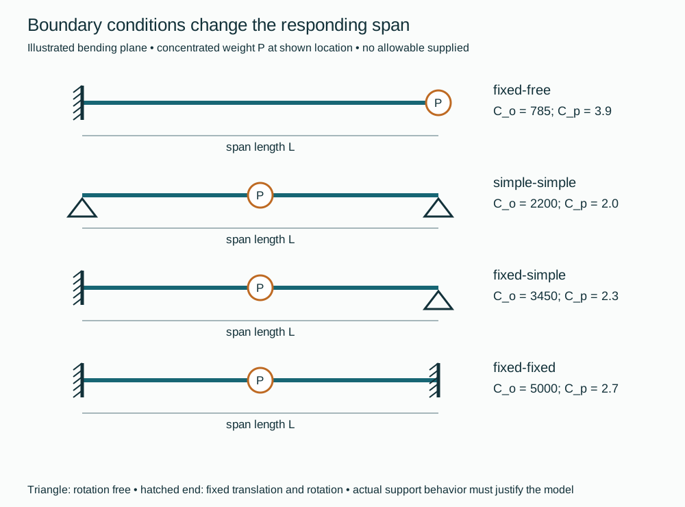
*Figure 10.6. Authored semantic diagrams of the four idealizations in Table 10.4. A triangle permits end rotation. A hatched end represents fixed rotation and translation in the illustrated bending plane. The concentrated weight is at the indicated point. Actual support stiffness, gaps and other directions remain separate model inputs. The [structured companion](assets/C09/c09-frequency-boundaries.json) records each geometry and coefficient pair.*
The method's coefficient is based on empty carbon-steel pipe. Its historical stainless adjustment lowers $C_o$ by 7%. It separately gives a diameter/wall-based water correction curve. Contents and insulation add mass, and a different material or temperature can change stiffness.
Those corrections require their own applicable basis. An unknown weight-table cell is not zero. A curve read is not an exact constant for every filled line.
These estimates do not calculate dynamic stress, damping, local fatigue demand or equipment acceptance. Complex connected spans and real boundary compliance can require a fuller modal model.
Compare the natural response with actual forcing and harmonics. For the described double-acting single-cylinder machine, pulsating-flow frequency is twice shaft speed in revolutions per second.
One adopted equipment criterion requires separation through the fourth forcing harmonic. Another metering-pump guideline proposes natural frequencies much higher than pulsating flow, for example at least five times it.
These bases address different arrangements. Neither equals a universal target of four times shaft speed, nor proves that a chosen support has removed all significant excitation.
Adding a restraint to shift a mode also changes thermal response. Its restrained direction needs evaluation against thermal displacement. A thermal null point in one direction can be useful without being fixed in all directions or all states. When a practical restraint cannot sit at that point, iterate location, flexibility and frequency rather than declare the highest frequency best. Verify the changed operating response and local attachment. The model’s frequency output alone is insufficient.
#### Preserve the plane, leg lengths and weight convention for a bent span
The straight-span coefficients cannot be carried into a bend merely by adding the leg lengths. Three further idealizations in Figure 10.7 retain both the shape and the direction of bending:
- An equal-leg right-angle span with fixed ends
- A portal with both feet fixed
- An equal-leg stepped span with fixed outer ends
Their concentrated weight is at the indicated location.
For these cases, use the preceding equation with $L$ as the **individual marked leg length**. Use $W$ as the total distributed weight of the illustrated span. Thus uniform pipe weight $w$ gives $W=2wL$ for the right angle and $W=3wL$ for the portal and stepped configurations. This $L$ is neither the total developed length nor a straight chord joining the terminals.

*Figure 10.7. Conditional empty-carbon-steel frequency idealizations. A–C have equal marked lengths L and the listed concentrated-weight locations. D–E have a short fixed leg $L_1$, a horizontal leg $L_2$ and an opposite leg $L_3$. Concentrated weight P is at distance $\ell$ from the lower end of $L_3$. D permits rotation at that end. E fixes it in the illustrated plane.*
*All geometry is schematic. In-plane motion lies in the drawn piping plane. Out-of-plane motion is normal to it. [Structured configuration and equation data](assets/C09/c09-bent-offset-frequency.json) preserve the associations.*
*Table 10.5. Bent-span coefficients for the stated empty-carbon-steel method and the exact idealizations in Figure 10.7A–C.*
| Configuration and weight location | In-plane $C_o$ | In-plane $C_p$ | Out-of-plane $C_o$ | Out-of-plane $C_p$ |
| --- | --- | --- | --- | --- |
| A: right angle, P at midpoint of horizontal leg | 3,430 | 0.28 | 830 | 0.28 |
| B: portal, P at midpoint of top leg | 690 | 0.61 | 450 | 0.70 |
| C: stepped span, P at midpoint of vertical leg | 620 | 0.66 | 500 | 0.68 |
The directional coefficients can differ substantially; a brace chosen only from an in-plane response can miss out-of-plane bending.
The unequal three-leg offsets D and E use a separate relation. It applies to **in-plane vibration only**, with $L_1$ the shortest anchored leg, $L_2$ the horizontal leg and $L_3$ the opposite leg. All lengths, including $\ell$, are in feet. $k$ remains in inches. Write the distributed weight per unit length as $w_1$ in lbf/ft. The dimensionless concentrated-to-short-leg weight ratio and mass-position ratio are:
$$\mu=\frac{P}{w_1L_1},\qquad q=\frac{\ell}{L_3}.$$
The shorter leg's distributed weight $w_1L_1$ is used here, not the total weight $W$ from the preceding coefficient table. For a uniform pipe section the same weight per length applies to all three legs. The two configuration factors are:
$$C_D=\left\{1+4.24\left[\frac{L_2}{L_1}+\frac{L_3}{3L_1}+q^2\mu\right]\right\}^{-1/2},$$
$$C_E=\left\{\frac{1+(L_1/L_3)^3}{1+L_3/L_1+4.24\left[L_2/L_1+\frac14(3q^2-q^3)^2\mu\right]}\right\}^{1/2}.$$
For the matching geometry, the frequency estimate is:
$$f_n=\frac{785k}{L_1^2}C_D\quad\text{or}\quad f_n=\frac{785k}{L_1^2}C_E,$$
The frequency estimates are in Hz. The entire $3q^2-q^3$ term in $C_E$ is squared. Changing that grouping or using $w_1$ without multiplying by $L_1$ changes the method. The simple-end and fixed-end configurations retain different factors even when their drawn lengths are identical.
Concentrated-weight position enters through $q$; moving the same mass along the leg changes its frequency contribution. [Saved calculation data](assets/C09/c09-bent-offset-calculations.json) and the [reproduction script](assets/C09/c09-bent-offset-reproduce.py) expose the example ratios and denominators.
These coefficients and offset equations start from an empty carbon-steel basis. The method's separate stainless correction and diameter/wall-dependent water correction belong to their stated scope. The offset sheet applies those corrections to its configuration factor. No water-curve value is supplied by this reconstruction, and the retained unknown pipe-weight cells cannot provide $w_1$ or $W$ as zero. Use known section and weight data or keep the evaluation incomplete. A different material, temperature, nonuniform section or actual boundary compliance needs its applicable model rather than an unexplained reuse of the coefficients.
The offset guidance also records fatigue failures at the anchored end of the shortest leg in metering-pump service. It proposes restraining axial movement of the horizontal leg as a remedy. That observation identifies the movement path and the local root to investigate. It does not turn a calculated frequency or one added support into general metering-pump acceptance.
An axial restraint changes the configuration for which these equations were written and also changes thermal movement. Reevaluate frequency, excitation, local stress and flexibility for that new configuration instead of continuing to quote the unrestrained estimate. [Appurtenance geometry](#c07-hardware-inertial-model) supplies a complementary force-to-section account when measured accelerations and a stiff attachment justify it.
### Keep an immersed thermowell's wake separate from the external span
An immersed well is excited by its own crossflow wake. One bounded historical circular-cylinder estimate uses $f_s=0.2V/D$ for Reynolds numbers up to $10^5$. In this estimate, $V$ is in ft/s and thermowell diameter $D$ is in ft, giving shedding frequency $f_s$ in Hz. The associated guideline compares the well's natural frequency with at least $1.5f_s$ at maximum expected flow. This is a restricted preliminary frequency comparison. It is not a complete thermowell pressure, fatigue, geometry or current standard qualification.
The actual well profile, support and flow range need their qualified evaluation. The external nipple/valve assembly has a different natural response; its span estimate cannot qualify the immersed stem.
### Compare the same fatigue quantity over the relevant operating range
Displacement at a point is evidence of response, not a local stress limit. Motion can be small near an anchor while curvature and alternating stress are high. Obtain the measured frequency, direction and amplitude convention with enough spatial and operating-state information to evaluate the relevant span or detail.
The stiff-appurtenance method in [Small-bore connections](#c07-inertial-method) already relates measured acceleration and mass/lever arms to local bending, with phase/sign and separate parent-pipe evaluations. Do not substitute a main-span displacement limit for that evaluation.
A fatigue curve can use stress range while the calculated or measured response uses amplitude. For a symmetric fully reversed sinusoidal stress, $\Delta\sigma=2\sigma_a$. A specifically adopted historical butt-welded carbon-steel atmospheric/noncorrosive basis without significant geometric concentration uses a 9.0-ksi design stress range. On that basis alone, the corresponding amplitude is 4.5 ksi. Its operating-vibration procedure halves the selected design value when only spot observations are available, giving 4.5 ksi of range or 2.25 ksi of amplitude.
The observation factor and range-to-amplitude conversion are separate operations. Neither is a new stress-concentration factor.
These values are not generic endurance limits for every piping weld, stainless or nonmetallic construction, corrosive environment, high temperature or damaged detail. An appropriate local factor and material/detail/environment basis remain necessary. Spot-observation allowance also does not establish that the unobserved worst operating condition is bounded.
[Operating integrity](#chapter-c19) retains the observation and response account. The analysis should say whether the operating range was actually monitored and how the selected fatigue basis treats that limitation. Cycle-count time explains urgency but supplies no universal failure life or repair deadline. [Structured method and result data](assets/C09/c09-enrichment-methods.json) keep the numerical examples distinct from project acceptance.
#### Compare a defined finite-cycle exposure with a compatible design curve
A steady vibration and an infrequent transient can accumulate very different numbers of stress cycles. The historical design curve in Figure 10.8 adds a finite-cycle comparison to the 9.0-ksi endurance-range example above. Its sloping portion permits higher design stress ranges at lower cycle counts, then approaches the stated plateau. It is a design relation with a built-in margin, rather than a measured failure-life curve.
Its scope is full-penetration butt-welded carbon steel in atmospheric, noncorrosive service with no significant geometric stress concentration. A different weld detail, a branch root, corrosion damage or a different material needs its compatible fatigue basis before these ordinates can be used.
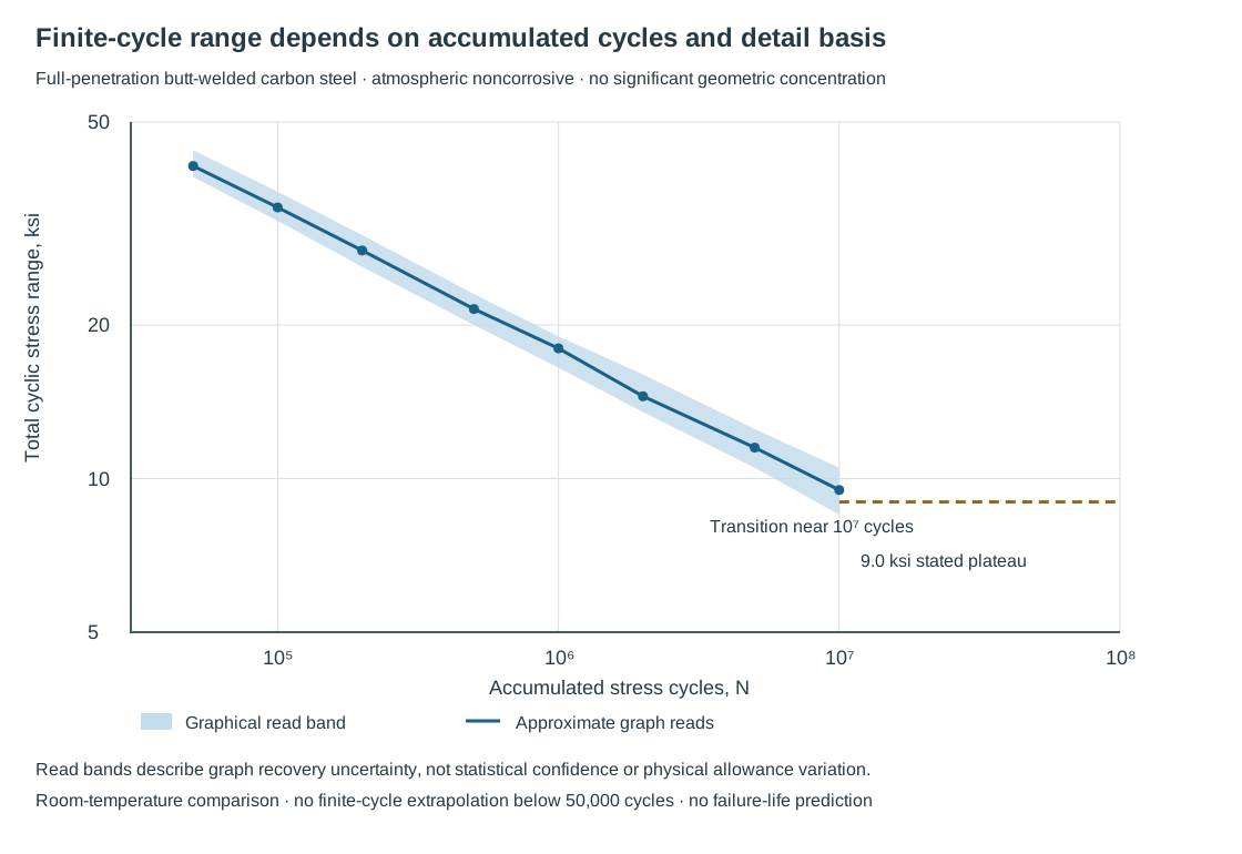
*Figure 10.8. A bounded graphical reconstruction on logarithmic axes. Points and the connecting path represent approximate reads over $5\times10^4$ to $10^7$ cycles. The shaded band shows graphical read uncertainty, not statistical confidence or permitted physical variation. The dashed 9.0-ksi line is the separately stated endurance-range level. Its transition occurs around $10^7$ cycles. That cycle count is approximate.*
*The finite-cycle path is not extrapolated below its recovered range. [Structured curve data](assets/C09/c09-finite-cycle-fatigue.json), [calculation data](assets/C09/c09-finite-cycle-comparisons.json) and the [reproduction script](assets/C09/c09-finite-cycle-reproduce.py) preserve the inputs and distinctions.*
*Table 10.6. Approximate total cyclic stress-range ordinates for the stated historical welded-carbon-steel design basis.*
| Cycles $N$ | Approximate range, ksi | Graphical read band, ksi |
| --- | --- | --- |
| 50,000 | 41 | 39–44 |
| 100,000 | 34 | 32–36.5 |
| 200,000 | 28 | 26–30 |
| 500,000 | 21.5 | 20–23 |
| 1,000,000 | 18 | 16.5–19 |
| 2,000,000 | 14.5 | 13.5–16 |
| 5,000,000 | 11.5 | 10.5–12.5 |
| Around 10,000,000, near the transition | 9.5 | 8.5–10.5 |
These coarse values retain the limits of a plotted curve without inventing exact numerical fatigue coefficients. For an intermediate cycle count within the recovered sloping region, interpolate between adjacent reads in log-cycle and log-stress coordinates. For endpoints $(N_1,S_1)$ and $(N_2,S_2)$, with $S$ a stress range in ksi, the graphical interpolation is:
$$u=\frac{\log(N/N_1)}{\log(N_2/N_1)},\qquad
S(N)=S_1\left(\frac{S_2}{S_1}\right)^u,\qquad N_1\leq N\leq N_2.$$
To retain the read uncertainty:
- Use the same construction for the lower and upper read bands.
- Preserve the resulting interval in the comparison.
This is an interpolation convention for the recovered graph, not an independently established fatigue law. A point whose demand lies inside the read band cannot be settled by displaying more digits from the interpolation.
The evaluated stress must have the same quantity and local-detail basis as the ordinate. For a symmetric fully reversed sinusoidal stress, total range is $\Delta\sigma=2\sigma_a$. Compare demand with the entire read band: below it, above it, or unresolved within it. Such comparison does not predict fracture or grant an operating interval.
For constant-frequency exposure, $N=ft$, with $f$ in Hz and $t$ in seconds. Repeated constant-frequency bursts can be counted by summing $f_jt_j$.
Calendar time includes inactive periods and is therefore a different quantity. When stress level or detail changes between intervals, simply adding cycles and comparing the total with one stress ordinate does not establish cumulative fatigue damage. That evaluation needs its own qualified history and damage method. Cycle counts are neither failure predictions nor repair deadlines.
The local stress account remains essential even for a curve with a built-in design margin. Measured displacement, a nominal straight-pipe stress and an intensified branch-root stress are not interchangeable. The evaluation needs the stress location, direction, range/amplitude convention and applicable local factor. A factor already contained in the selected detail assessment must not be counted twice.
A stress concentration cannot be ignored because a pipe's global motion is small. Nor does this butt-weld curve become a general branch or threaded-joint curve by relabeling its ordinate.
Keep temperature and environment local to the decision. The historical discussion treats a room-temperature carbon-steel endurance limit as constant up to 750°F for its purpose, but does not supply a temperature-dependent finite-cycle curve. That endurance statement cannot establish the entire sloping relation at elevated temperature. The finite-cycle comparison here retains a room-temperature, atmospheric, noncorrosive basis. A higher-temperature or aggressive-environment evaluation needs a compatible basis, including the effect of metal loss and changed local stress.
A monitored operating envelope differs from a spot observation. The factor of two described above is specified for design endurance limits when observations may miss the worst condition. It does not supply a separately established finite-cycle curve obtained by halving every ordinate in this table.
A finite-cycle exposure decision needs its stress and cycle history bounded over the relevant operating conditions. One measured amplitude does not provide that history. Use the curve to organize the required comparison and uncertainty. The investigation below establishes the actual motion, operating state, damage condition and remedy.
## Investigate the actual operating condition and recheck the remedy
When vibration occurs, record its operating condition:
- Record the equipment running, flow and phase.
- Record the pressure, temperatures, valve positions and transient stage.
To investigate the response:
- Locate the moving spans, attachments and supports.
- Inspect for cracking, looseness, lost contact or damage.
Appropriate measurements describe displacement, velocity or acceleration with frequency, location, direction and amplitude convention. A visual impression without those relationships cannot establish compliance with a numerical vibration criterion.
Separate source correction from response modification. Correcting an unsuitable control-valve application or reducing avoidable cavitation addresses the forcing. Changing a span, adding a restraint, reducing appurtenance mass or altering a support addresses response. For reciprocating equipment, the connected acoustic and mechanical system can require a pulsation study rather than isolated bracing. A remedy must be evaluated under the relevant service and operating range.
A new vibration restraint also affects thermal behavior. Where possible, locate a suitable restraint with little thermal movement in its constrained direction. Then reevaluate flexibility and natural response. If that position is impractical, iterate both evaluations rather than claim that any added steel is an improvement.
Test the changed arrangement in the operating state that produced the problem. Examine the affected details. Suppressed visible movement alone does not prove an existing crack repaired.
Retain the evaluated model, assumptions, geometry, material/temperature data, terminal movements, support characteristics, cases and equipment reactions. Connect them to the actual settings and configuration established in construction and readiness. [Operating integrity](#chapter-c19) and [Change](#chapter-c20) return observations and altered conditions to that basis. The analysis remains useful when the next participant can identify which physical relationship a change has modified.
# Chapter 11 — Support and restraint decisions through the lifecycle
## Carry the load while preserving the intended movement
A sliding shoe carries weight while allowing travel; a guide directs that travel, a stop limits one direction, an anchor fixes specified freedoms, and a spring carries weight through vertical movement. Near a nozzle, support can reduce weight moment while restraint increases displacement load. Select the carried loads and permitted movements together, with acceptable pipe, attachment, equipment and structural reactions.
The numerical support-selection criteria below apply to a defined aboveground metallic process-piping scope. They are drawn from criteria for ASME B31.3 metallic piping at temperatures of 427°C (800°F) and below, excluding cryogenic service below −101°C (−150°F).
Use those criteria only where the project adopts that scope. Cold-insulated piping still needs insulation and vapor-barrier treatment, while cryogenic systems need a separately established selection basis. For an application, establish the governing code edition, project criteria and equipment limits. The historical standards references discussed here do not establish present compliance.
## The line has several mechanical states
Include pipe, fittings, valves/operators, lining, insulation and contents, including test liquid for vapor-service lines and project-required snow/ice. Concentrated masses can govern differently from uniform pipe weight.
Equipment movement, settlement, wind, seismic effects where applicable, relief reactions, water hammer and other mechanical loads can further change support demand.
Temperature must be described as a sequence of credible conditions, not a single operating value. Start-up, shutdown, steam-out or decoking, depressuring, regeneration and defined upsets can produce movement or displacement ranges that normal operation does not reveal. A parallel pump branch may remain cold while the header and neighboring branches are hot. Different branches can be cold on different occasions. A support scheme that accommodates every line at one uniform temperature may therefore miss the relative movement that governs a connection.
Installation creates another state. The pipe may be empty, insulation incomplete, springs locked and some equipment not yet connected. A vertical vessel may be fitted with piping while horizontal. Its attachments and guide brackets must therefore carry a temporary direction of gravity loading. Hydrotesting adds liquid and pressure, may isolate the line at temporary blinds, and may require temporary support or spring blocking.
The support system also changes when contact changes. A resting shoe cannot carry downward weight reaction through a support it has lifted clear of. Retaining that support as active in a sustained-load calculation creates a load path that no longer exists. Where thermal movement causes lift-off:
- Remove the lifted support from the applicable sustained-load representation; or
- Consider a spring that maintains the weight-support path.
Examine both hot and cold contact configurations.
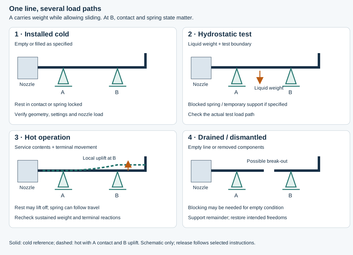
*Figure 11.1. A conceptual state model for one equipment-connected line. The upward movement in operation is an assumed example, not a prediction for every line. Support A is a sliding rest. Support B is either a rest that can lose contact or a selected spring.*
*The test and maintenance configurations require their own load-path checks. The structured companion records the states, assumptions and transitions. Neither representation supplies dimensions or allowable loads.*
## Locate support from the actual span and weight arrangement
Span selection begins by identifying how the pipe is supported. An interior span of a continuous run has neighboring spans that resist end rotation. A simple branch span has more freedom to rotate at its ends. An unsupported overhang can both rotate and deflect, and a turning overhang can interact with the adjacent leg. The same size and weight therefore do not imply the same permissible spacing in all three configurations.
Break the route into actual spans and overhangs, including changes caused by lift-off or component removal.
The continuous-run lookup discussed here assumes at least two identically supported spans on either side of the span being considered. A first or last span cannot inherit that interior condition automatically. A nozzle is also not an ordinary support. Its local reaction cannot be accepted without evaluating the equipment.
The selected historical lookup below compares continuous and branch spans. It is a preliminary method with specific assumptions:
- Water-filled piping
- Insulation for 450°F
- Schedule 40 for NPS 2–6
- Schedule 30 for NPS 8–12
- Schedule 20 for NPS 14–24
The underlying limits combine longitudinal bending stress of 9,000 psi or less with deflection judged acceptable by the method's experience. These are conditions of this lookup, not universal stress or sag limits. The lookup method's normal pipeway arrangement uses 20–25 ft spacing even where a larger line's tabulated span is longer.
*Table 11.1. Conditional continuous-span and branch-span lookup.*
| Nominal pipe size | Wall basis in this lookup | Continuous interior span, ft | Branch span, ft |
| --- | --- | --- | --- |
| 2 | Schedule 40 | 25 | 20 |
| 4 | Schedule 40 | 36 | 30 |
| 6 | Schedule 40 | 44 | 35 |
| 10 | Schedule 30 | 55 | 40 |
| 12 | Schedule 30 | 56 | 40 |
| 24 | Schedule 20 | 70 | 50 |
Heavy valves, changed temperature or lining, and hot-support loss can invalidate the lookup basis and require separate evaluation.
Concentrated loads deserve a support near their load path where practical. A heavy valve or a vertical riser can create local bending and reactions that uniform-weight spacing does not represent. The support must still preserve movement and maintenance access. Supporting a pump-side valve through a removable pump leaves no permanent load path when the pump is taken away. A scheme intended to permit that repair should carry the remaining pipe and valve independently in the disconnected state.
Sag matters beside stress. A span that remains below a bending limit can retain liquid, defeat an intended slope or lose clearance. Different adopted procedures can specify different maximum sag: one uses 5/8 in, another 1 in and allows reduction for drainage. Keep the selected limit and function together. Choosing the larger number is not a general optimization rule.
Overhangs and dynamically loaded spans require their own treatment. [Mechanical analysis](#chapter-c09) evaluates the resulting stress, deflection, contacts and equipment reactions.
### Match a static span lookup to the illustrated route
Two further metallic span sets below apply to pipes resting on **more than two supports**. They retain their own material, wall, temperature and weight conditions. Set A covers these material and wall conditions:
- Carbon steel at STD wall or heavier, up to 350°C
- Austenitic stainless steel at Schedule 40S or heavier, DN below 400, up to 350°C
- Duplex stainless steel at Schedule 10S or heavier, up to 280°C
Set B covers austenitic stainless steel at Schedule 10S up to 350°C. A DN 400 row in Set A therefore does not extend its austenitic applicability past the stated DN limit. These sets are distinct from the preceding water-filled, 450°F continuous/branch lookup. Neither its wall basis nor its values can be silently substituted into them.
Choose the material set, nominal-size row, vapor/liquid service and bare/insulated column before applying a shape factor. The tabulated $L$ is the straight-pipe span in millimeters. For only the configurations illustrated in Figure 11.2, the selected method gives:
$$L_1=0.65L,\qquad L_2=0.75L.$$
The dimension lines and support stations define the corresponding bent or offset span. When laying out the supports, retain that graphical definition. Do not replace it by an unrelated terminal chord, total run length or one arbitrarily chosen leg. For another route shape, establish its own span/weight model. These factors reduce a static span lookup. They are not the in-plane/out-of-plane natural-frequency coefficients in [the vibration method](#c09-bent-offset-frequency).
*Figure 11.2. Native schematic reconstruction of the two shape definitions. Crosses mark the indicated support stations. The dimension paths retain the selected bend/offset construction. $L$ comes from the applicable straight-span table, and $L_1$ or $L_2$ belongs only to the corresponding illustrated shape. No dimensions of a real installation are supplied. [Structured geometry, full lookup data and conditions](assets/C10/c10-shape-span-lookup.json) retain the associations.*
*Table 11.2. Set A maximum straight spans, mm, under the material/wall/temperature conditions above.*
| DN | Vapour, bare | Vapour, insulated | Liquid, bare | Liquid, insulated |
| --- | --- | --- | --- | --- |
| 25 | 3,850 | 2,300 | 3,450 | 2,250 |
| 40 | 4,750 | 3,000 | 4,100 | 2,800 |
| 50 | 5,350 | 3,600 | 4,550 | 3,300 |
| 80 | 6,550 | 4,600 | 5,450 | 4,200 |
| 100 | 7,500 | 5,550 | 6,100 | 4,900 |
| 150 | 9,150 | 6,800 | 7,100 | 5,800 |
| 200 | 10,500 | 8,050 | 7,950 | 6,700 |
| 250 | 11,800 | 9,050 | 8,700 | 7,400 |
| 300 | 12,900 | 9,800 | 9,150 | 7,800 |
| 350 | 15,150* | 11,850 | 10,850 | 9,300 |
| 400 | 16,250* | 12,850 | 11,200 | 9,750 |
| 450 | 17,250* | 13,750 | 11,500 | 10,150 |
| 500 | 18,200* | 14,450 | 11,750 | 10,400 |
| 600 | 18,950* | 16,050 | 12,150 | 10,950 |
*The five starred bare-vapour cells are limited by deflection. All other Set A cells are limited by longitudinal bending stress under this method.*
*Table 11.3. Set B maximum straight spans, mm, for austenitic stainless Schedule 10S up to 350°C. All cells are limited by longitudinal bending stress under this method.*
| DN | Vapour, bare | Vapour, insulated | Liquid, bare | Liquid, insulated |
| --- | --- | --- | --- | --- |
| 25 | 3,900 | 2,200 | 3,450 | 2,100 |
| 40 | 4,850 | 2,800 | 4,000 | 2,600 |
| 50 | 5,450 | 3,300 | 4,300 | 3,000 |
| 80 | 6,700 | 4,050 | 4,950 | 3,500 |
| 100 | 7,650 | 4,800 | 5,300 | 4,000 |
| 150 | 9,400 | 5,750 | 5,950 | 4,600 |
| 200 | 10,750 | 6,800 | 6,450 | 5,200 |
| 250 | 12,000 | 7,600 | 6,950 | 5,650 |
| 300 | 13,000 | 8,250 | 7,350 | 6,050 |
| 350 | 13,750 | 8,700 | 7,600 | 6,300 |
| 400 | 14,700 | 9,450 | 7,750 | 6,550 |
| 450 | 15,650 | 10,150 | 7,850 | 6,750 |
| 500 | 16,450 | 11,000 | 8,400 | 7,300 |
| 600 | 18,050 | 12,700 | 9,050 | 8,050 |
Both insulated columns include insulation and sheeting. Their insulation basis varies from 70 mm thickness at DN 25 to 200 mm at DN 600, with density 190 kg/m³. That stated range does not supply an exact thickness at every intermediate size. Actual insulation, sheeting, contents and concentrated component weights must agree with the selected basis or be evaluated separately. The liquid-column heading alone does not establish a universal fluid-density permission.
Free-draining piping with slope below 1.5 mm/m requires an additional span evaluation. Sag can defeat drainage even when the tabulated bending or deflection condition is met.
Material/wall changes can change the applicable set and span. Do not select the heavier-wall set solely for its larger values. Equipment reactions, local bearing, lift-off, test weight, thermal movement, vibration and receiving structure remain separate evaluations; passing the table does not establish drainage margin. [Lookup/comparison data](assets/C10/c10-shape-span-calculations.json) and the [calculation script](assets/C10/c10-shape-span-reproduce.py) preserve illustrative rows and assumptions.
## Choose support behavior before choosing a detail
A sliding rest is attractive when the line can carry its weight through a bearing point and remain on that point over the required travel. Its shoe must be long enough to avoid moving off the supporting steel during expansion or contraction. The sliding surface does not make the system frictionless. Resistance to movement changes reactions at anchors, guides and terminals. Its effect must be considered in both the piping and support design.
The analysis convention used here does not credit friction merely to obtain lower pipe loads or stresses. Its allowance for assuming frictionless unrestrained movement is limited to a system supported entirely by rod or spring hangers. Even when that convention applies, consider hanger geometry. Rod rotation can alter the load transmitted to a nearby nozzle.
Where the line moves vertically, a rigid rest may either resist that movement or lose contact. A spring offers a different load path. It carries a selected load while allowing vertical travel. A variable spring changes force through that travel. A constant support is intended to maintain supporting effort over its range. Selecting a spring therefore requires load and movement data, not only a pipe size.
A project may use a 25% installed-to-operating load-variation criterion. Under that criterion, a variable support may be selected at or below the limit. A constant support is specified above it. The reference load and calculation convention for that percentage must be defined in the project selection procedure. The criterion alone does not supply a denominator.
A constant support can also be appropriate for large vertical movement or when a variable spring becomes impractical. It can also be appropriate when changing spring reaction would transfer excessive load to a critical terminal. Check the actual load-sensitive equipment as well as the selected percentage criterion.
### Route the attachment choice through the material and thermal interfaces
After selecting the required support behavior, choose the way the reaction reaches the pipe. Figure 11.3 shows a conditional metallic-piping selection route. It starts with insulation. Exposed pipe bearing on steel, a shoe on a hot line and a clamp outside cold insulation have different structural and thermal interfaces.
A cold-insulated line leaves the ordinary shoe-selection route for its qualified insulation-system procedure. The support must carry the required loads without opening the moisture barrier. Load-bearing insulation, friction and erection/test sequence must be established together. [the cold-support account below](#c10-cold-support-sequence) develops that interface.

*Figure 11.3. Conditional selection questions for the stated metallic-support procedure. “Yes” and “no” preserve the branches and shared joins, including the separate cold-insulation route and special clamped/welded exits. CS means carbon steel and SS means stainless steel. The direct-bearing endpoint still needs the design conditions discussed here. The [structured question map](assets/C10/c10-selection-questions.json) retains every node and branch. The endpoints select an attachment route, not an allowable reaction.*
For an uninsulated pipe, the illustrated route asks successive questions:
- Is fluid temperature below ambient?
- Does the pipe need a slope?
- Is size above DN 600?
- Is wall below Schedule 20 for carbon steel or Schedule 10S for stainless steel?
Any “yes” moves the line into shoe selection. Only “no” to all four reaches direct bearing on the supporting beam. The design conditions also exclude direct bearing where sufficiently low temperature can embrittle the receiving member. They exclude it where pipe movement and water collection can cause unacceptable corrosion.
A pipe shoe protects the pipe interface. It does not cure corrosion of the supporting steel. These additional conditions must travel with the question map. A slope correction remains small under this procedure, which limits shoe height measured below the pipe to 400 mm.
Within shoe selection, a noncorrosive carbon-steel line follows the clamped route. A corrosive environment or another metallic material first reaches the lining/coating question. A lined or corrosion-resistant-coated pipe follows the clamped route. Otherwise, the need for post-weld heat treatment sends it to the clamped route. Absence of that need reaches the welded route. On either route, high forces/moments or temperature above 400°C requires a specially designed support of that attachment type.
The questions contain no numerical definition of “high” load. Compare the evaluated load with the selected hardware’s applicable geometry, material and temperature capacity. Do not invent a threshold from the diagram.
The accompanying design conditions qualify those outcomes. Welded supports are excluded on:
- Glass-, rubber- or plastics-lined piping
- Piping requiring PWHT
- Corrosion-resistant coatings such as galvanizing
- Specified expensive materials such as titanium, Hastelloy and Monel
A branch reaching “welded” cannot override those exclusions. If a supporting attachment is required on PWHT piping, its separate fabrication route identifies it on the isometric. The attachment is made in the workshop before heat treatment. That shop sequence does not permit an unrestricted field weld. Supporting attachments welded directly to pipe use the same material type and carry their identification into the drawing.
Clamps retain their own conditions:
- Protect against retained water.
- Where needed, provide appropriate insulating separation between a carbon-steel clamp and another metallic pipe.
- Evaluate loss of grip as clamp and pipe change temperature differently.
Where the procedure calls for weld-on shear lugs to prevent slip, restore the affected paint after welding. That local weld is itself subject to the pipe’s material, treatment and examination requirements. A clamp endpoint therefore does not remove all welding or inspection decisions.
For hot insulated piping above 400°C, the procedure calls for alternatives. These are incombustible blocks with adequate thermal and load-bearing properties between shoe/cradle and structure, or a qualified clamp around load-bearing insulation. For insulated piping generally, maintain at least 50 mm clearance to the supporting structure.
The cold-insulation route includes movement in that clearance and checks friction against the insulation's capacity. Glass-lined and plastic systems retain their supplier's installation instructions. The metallic map cannot assign their bearing or attachment capacities. Galvanized supports are excluded by this procedure for austenitic and duplex stainless steel, nickel alloys and 9% nickel steel.
The selected attachment, freedoms, local wall, receiving steel and foundation must carry the actual reactions. Preserve the material/fabrication route, insulation/barrier treatment, weld/examination requirements and installed freedoms in the detail.
### Size and maintain the sliding interface
Friction belongs to the contact that actually carries the line in the state being examined. In a simple dry-contact model, the limiting static tangential resistance is $F_{s,lim}=\mu_s N$. In this equation, $N$ is the compressive normal reaction. $\mu_s$ is the dimensionless static coefficient for the adopted surface pair. If $N$ is in kN, the limiting force is in kN.
Before slip, friction responds to the demanded tangential force up to that limit. It is not always equal to $\mu_s N$.
The relation supplies neither a kinetic coefficient nor a complete thermal-displacement solution. If the support lifts clear, the compressive contact and its friction path disappear. Use the reaction at that support rather than dividing the total line weight equally among supports without justification.
One specifically adopted support-design basis uses the following static coefficients. They are design inputs of that basis, rather than measured constants for every installed surface or permissions to substitute material pairs.
*Table 11.4. Static-friction inputs under one adopted sliding-support basis.*
| Contact pair | Static coefficient, $\mu_s$ |
| --- | --- |
| PTFE on PTFE | 0.10 |
| PTFE on stainless steel | 0.10 |
| Steel on steel | 0.40 |
| Steel on concrete | 0.45 |
The displacement solution must reconcile friction with restraint stiffness, thermal growth, load redistribution and contact. An adopted prohibition on beneficial friction credit remains controlling even if adding friction lowers one numerical reaction.
A low coefficient is useful only while the interface preserves the conditions on which it depends. Corrosion, sand and dirt can increase resistance, while damaged bonding can change contact or let a pad move independently of its backing. One support procedure therefore specifies a stainless landing surface. It minimizes low-friction elements because even that surface can foul. Where low friction is necessary and the hanger’s service restrictions permit it, the procedure considers a hanger. The alternative retains the rod-swing and fire-exposure questions already discussed.
Other adopted details deliberately use PTFE on a stainless mating pad. They protect the pad from weld spatter and require cleaning loose particles before loading the line. A graphite pad's bonding method needs demonstrated performance in similar applications under its selection procedure. These are construction and maintenance conditions of the load path, not finishes that can be selected after the analysis is complete.
The bearing temperature also has a local reference. The PTFE shoe and adjustable-base details considered here limit metal temperature **at the PTFE** to 400°F (about 204.4°C). This is a restriction of those particular details. A process-fluid temperature, the opening chapter's metallic support range, or a different PTFE product rating cannot establish that this interface meets it.
Establish the temperature at the bearing and the qualified load and attachment arrangement before selecting the detail. Conversely, a hot line does not establish the pad temperature without evaluating the intervening shoe and heat path.
Travel needs a swept bearing area. Under the adopted PTFE-pad procedure, the upper pad must overlap the lower by at least 1/2 in in both cold and hot positions. Alternatively, a cover must prevent dirt reaching the pads.
Distinguish that protective edge coverage from the separate need for sufficient load-bearing contact and shoe-to-beam support. A cover addresses contamination. It does not restore contact after a shoe runs off the beam. Loss of support followed by a temperature reversal can catch the shoe against the steel and damage the support or pipe.
For a centered rectangular pad, Let $L_u$ and $L_l$ be upper and lower pad lengths in the travel direction. Let $x$ be the upper pad’s displacement relative to the centered position, and $c$ the required edge coverage. Full lower-pad coverage with that margin requires:
$$\frac{L_u-L_l}{2}-|x|\geq c.$$
All quantities are lengths in the same units. Check both directions, actual cold/hot offsets and tolerances separately. This centered model does not reinterpret a catalog movement label or establish pad pressure, bond strength, support capacity or allowable temperature.
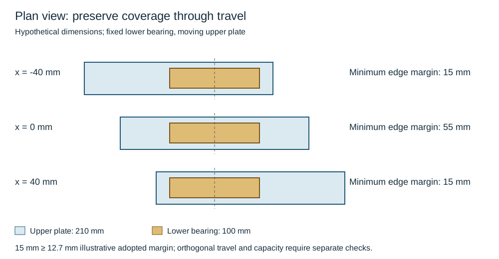
*Figure 11.4. Plan views of the authored rectangular example at three relative positions. The fixed lower bearing stays covered by the moving upper plate. The limiting longitudinal edge margin is 15 mm. Dimensions are hypothetical and the other direction is not assessed. The [structured companion](assets/C10/c10-pad-envelope.json) preserves the geometry, assumptions and checks.*
Choose a pad arrangement whose surfaces can be cleaned and whose coverage, bonding and travel can be observed. At commissioning, verify the installed relative position against the defined reference state. In operation or after adjacent work, unexpected restraint, debris, displaced pads or a shoe approaching an edge calls for investigation. Investigate the contact and movement basis before adjustment. Replacing a steel contact with a low-friction pad is a mechanical modification. It can change reactions and motion elsewhere even when the nominal support location stays the same.
### Relate spring load change to travel
A variable support may operate over a range in which its rate can be treated as linear. In that range, the magnitude of load change is $|\Delta Q|=k|\Delta y|$. $Q$ is supporting force, $k$ is spring rate in force per unit travel and $y$ is vertical travel. Direction determines whether travel loads or unloads the spring. The rate and usable travel come from the selected device. They cannot be inferred from pipe diameter alone.
If the selected procedure defines variation relative to operating load, use:
$$v=\frac{|Q_{installed}-Q_{operating}|}{Q_{operating}}.$$
That denominator is conditional, not supplied by the bare 25% criterion. Use the prescribed convention. Satisfying its percentage still leaves capacity, travel, terminal reactions and intermediate/empty states to be checked.
For an initially vertical fixed-length rod of length $\ell$, the simple pivot model gives horizontal shift $x=\ell\sin\theta$. An adopted 4° swing limit therefore requires $\ell\geq |x|/\sin4^\circ$ for that geometry. Vertical movement and actual attachment geometry can change both travel and force.
A constant support is selected for its specified supporting effort and travel, not by assigning a smaller rate to an arbitrary variable spring. Calibration, load indication, available movement and the cold/hot reference settings are necessary parts of the actual device. Keep the selection data connected to the installed hardware and to the test and empty-state instructions.
### Preserve the directions assigned to hangers and restraints
A suspended rod hanger can solve a lack of support space beneath the line, but horizontal movement swings the rod. Where the project adopts a 4-degree swing limit, size and position the hanger to respect it. Account for the rotation and its nozzle-load consequence in the analysis. A suspension arrangement that appears free in plan can therefore become unfavorable near a sensitive terminal. Under an adopted procedure that excludes hangers for two-phase flow or excessive vibration, that exclusion remains part of the support choice.
When a suspended rod cannot survive pool-fire exposure, a catch beam or other evaluated means of preserving support can be required. Coating the rod with fire protection is not automatically an adequate solution. Space, structural attachment elevation and the required travel belong in the choice between a hanger and a support from below.
Guides, stops and anchors control movement, stabilize geometry and resist static, transient or dynamic forces. Each restraint added to suppress an unwanted movement also changes the freedom available for thermal expansion. Natural flexibility from routing and fittings should be considered early, while rerouting remains practical. An expansion joint adds a specialized movement mechanism but also introduces anchor and guide obligations. An unrestrained joint cannot be accepted as an automatic cure for a stiff line. Pressure thrust and hydrostatic-test restraint must be considered, and the anchor-guide system must follow the applicable code and the established joint design basis.
This interplay is especially clear in vibrating piping. A restraint can increase stiffness and reduce vibration while worsening thermal stress. Thermal analysis can identify a point whose displacement in a particular direction is zero: a null point. Restraint in that direction at the null point can oppose vibration without obstructing the predicted thermal movement.
If the useful restraint cannot be located there, thermal and natural-frequency calculations must be repeated for the proposed position. A null point is tied to the analyzed condition and direction. It is not a universal permission to anchor the pipe in every direction or every state.
Reciprocating machinery requires a distinct dynamic treatment. Support locations and spans influence mechanical response to pulsating flow. A successful arrangement copied from another machine is not sufficient evidence for a new one. A metallic-support specification may require:
- Transverse restraint of pulsation-prone lines from reciprocating compressors or pumps, regardless of an acoustic study
- Evaluation of clamp coupling moments and dynamic loads
- Consideration of independent supporting structures where feasible
If that specification excludes sway braces for these lines, a generic vibration-control detail cannot override the exclusion. This treatment should not be generalized to every vibrating line. Acoustically induced vibration calls for assessment of vibration and fatigue. It also calls for consideration of suitable attachment forms, including bands, bolted supports or stiffening rings.
### Match a restraint's response to the motion being controlled
A direction label alone does not describe a dynamic device. A sway strut restrains a selected direction while allowing movement in another. A sway brace uses its adjustable spring or friction behavior to oppose sway, vibration or shock under its specification. A snubber offers a different response. It permits slow movement while resisting sudden motion. This can preserve gradual thermal travel while transmitting an impulse reaction from an earthquake, flow transient or wind gust.
Model the selected device's response and attachment direction rather than replacing it indiscriminately with an always-rigid anchor. Its usefulness depends on the actual transient and thermal sequence, load capacity and travel.
One specifically adopted mechanical-device specification reduces allowable material stresses by 50% for vibration duty. It requires buckling resistance and self-aligning spherical end bushings allowing at least 10° rotation in any plane. It provides a securely locked adjustment of ±40 mm. Its snubber requirement includes operation from 3 to 33 Hz. Snubbers and sway braces have readable travel scales. These values describe that specification, not universal capacities or tuning rules.
End articulation accommodates changing geometry. It does not permit the assembly to run out of stroke or the attachments to bypass their load checks. Preserve the separate prohibition on sway braces for reciprocating-machine lines where that support criterion is adopted.
Specify allowed movement, resisted transient, travel/force response and both end-attachment load paths. Preserve articulation, adjustment and access to indications/connections in installation. A travel scale does not prove dynamic response; inspection and functional testing follow the device’s qualified procedure.
## Follow the reaction beyond the pipe
A pipe-support detail is only one part of the load path. The shoe or clamp transfers load into a bracket or beam, then into structural framing, concrete or a foundation. Supporting several restrained lines on the same structure requires consideration of the most severe combination of their loads. A satisfactory individual support does not prove that the shared structure is adequate.
Likewise, paving or grating should not be treated as a structural foundation merely because it lies under the pipe. Establish its capacity and installation criteria. When paving capacity is exceeded, provide an independent foundation. Handrails, ladders and other structures not intended to carry these loads are unsuitable attachment points.
At equipment, include both force and moment. The nearby dead-weight support used for a vertical vessel line reduces the load imposed on its nozzle, while lower guides limit sway and associated moments. The vessel attachment must still carry the support reaction, including applicable temporary installation and hydrotest states. Heater piping illustrates coordination at a moving terminal. The supplier of a furnished manifold needs proposed piping loads and any movement associated with rod or spring support. The supporting steel and piping cannot be designed independently and reconciled only at erection.
Minimize weight and weight moment at load-sensitive equipment, then evaluate complete nozzle loading.
When the project criterion selects the lesser of manufacturer limits and applicable reference limits, evaluate both unless an authorized project decision establishes otherwise. API 618 and API 661 provide equipment-specific reference routes for reciprocating compressors and air-cooled exchangers respectively. The reference applicable to the actual equipment and contractual edition must be established. A generic terminal allowable is not justified by the fact that a stress calculation passes for the pipe.
Attachment design also interacts with the pipe wall. Welded attachments near elbows can reduce flexibility, and large thin-wall lines need evaluation for local crushing at concentrated support loads. For pipe greater than NPS 24, the selection criteria discussed here require determined allowable spans and bearing reinforcement or wear pads. These are local load-transfer questions as well as global span questions. A large line that passes an overall bending check can still require a different bearing arrangement.
Insulation adds both weight and an interface that must survive movement. Shoes on insulated lines provide a sliding surface without making the insulation carry damaging movement. Cold-insulated supports must avoid cold bridges, vapor-barrier penetrations, crushing, condensation and ice. Thermal and acoustic insulation thicknesses affect the support geometry. Do not resolve a support interference by cutting away insulation without reconsidering those functions.
Material and fabrication constraints can change the preferred attachment. Clamp-on shoes are an alternative when welding is forbidden or impractical, including internally lined or galvanized piping and piping requiring post-weld heat treatment. A fabrication procedure that restricts field attachment welding on these materials can require workshop attachment welding before heat treatment. Thus a last-minute support weld is not a neutral field correction. It can affect heat treatment, lining, coating and flexibility, and may require a different attachment or revised spool fabrication. Specify attachment materials using the applicable pipe material, service temperature and project rule.
Some temperature and material combinations permit carbon-steel attachments. Others require the pipe material or a compatible composition. “Match the pipe” alone does not resolve that selection.
### A process line used as a carrier acquires another load and movement role
An intermediate cross member can carry small lines between rack bents by hanging from larger process lines. In Figure 11.5A, the smaller-line reactions enter the cross steel, then its attachment or shoe, the carrier process lines and finally those lines' own supports. Reducing the smaller lines' unsupported length therefore increases demand in pressure-containing members. Evaluate the carrier’s bending, local attachment, contact and stability together with the cross member. Adequate smaller-line spacing alone does not establish that coupled load path.
The selected arrangement uses a U-bolt at an uninsulated carrier and a shoe welded to the cross steel at an insulated carrier. These labels do not establish a complete freedom set. Identify which interfaces grip, bear or slip and whether the two carriers can move differently. A cross member joining lines with different growth can restrain one or both, redistribute reactions and load the pressure-wall attachment.
An insulated carrier’s growth at the proposed station must be evaluated. Selecting another carrier or independent structural steel can avoid an unsuitable restraint. Any project prohibition on supporting one pipe from another remains controlling.
Consider the empty, filled, operating and test states of each participating line, including cases where one carrier is hot and the other is cold. Removal of a carrier or its shoe can interrupt support of lines that remain in service. Before dismantling such an assembly, provide a governed temporary load path. Retain inspection access to the carrier wall and attachment. Treat the configuration as an explicitly evaluated inter-pipe support arrangement, rather than a shortcut around structural steel design.
### A vessel-mounted guide has a moving reference and a sliding interface
Figure 11.5B shows a different pressure-boundary carrier. Vessel-mounted bars or plates lead to a pipe clamp around a vertical line. The selected guide detail has a sliding fit with diametral clearance, rather than a weight-support grip. Its purpose is to control lateral response while allowing the line's intended axial movement relative to the vessel. Define the actual clearance, friction, alignment and travel. A clamp symbol does not prove axial freedom after tightening, corrosion, insulation or field adjustment.
The vessel fabricator supplies the required shell-mounted attachment parts under this detail. Thin-wall shell distortion requires investigation, and guides should not be placed too close to a point where horizontal expansion would distort the guide or vessel. Vessel growth is a boundary movement, not stationary ground. To establish travel and loads:
- Combine the shell’s movement with the line’s growth to obtain relative travel.
- Then carry lateral guide reactions into the attachment and shell assessment.
A separate riser support carries weight. Neither guide spacing nor a sliding fit supplies that vertical load capacity.
The selected guide chart's spacing assumptions include wind on projected insulated pipe and a bounded deflection criterion. Its numeric spacing is not exported here as a universal interval. The native panel retains the contact and attachment topology without reconstructing an unresolved drawing-callout suffix. Actual bar/plate material, welds, clamp dimensions, clearance and guide spacing remain on their qualified detail basis. [Vessel-carried equipment and work structures](#c04-vessel-carried-work) pose the same load-owner question at a larger scale, with different loads and acceptance requirements.

*Figure 11.5. Separate conceptual arrangements: A, small-line reactions transferred through cross steel to two carrier process lines; B, a vessel attachment leading to a sliding guide around a vertical line. Arrows identify the evaluated load or movement direction, not allowable forces. [Structured interface data](assets/C10/c10-carrier-guide.json) keep the arrangements and their freedoms separate.*
### Establish the common structure's abnormal-load combination
An anchor bay carries the thrust through its frame and bracing into foundations. A support beam intended to carry ordinary pipe weight may have a different structural function. One long-run support basis normally assigns thermal thrust to anchor bays rather than to every elevated support. Accordingly, identify which members carry the restraining reactions, including their tensile and compressive paths. An anchor symbol does not demonstrate that the frame or foundation carries those reactions.
That same basis defines abnormal thermal conditions to include:
- Loss of cooling
- Stopped process flow with line heating still active
- Anticipated start-up, shutdown, steam-out and upset temperature changes
For the common anchor structure it adopts the following grouping. It also requires each piping anchor to be designed for the governing normal or abnormal force.
*Table 11.5. Conditional abnormal-line grouping for one anchor-structure design basis.*
| Lines at the structure capable of abnormal conditions | Fraction assigned abnormal conditions in this grouping |
| --- | --- |
| 1 | 100% |
| 2–4 | 50% |
| More than 4 | 25% |
Round the resulting number **up to the next whole line**. The selection note generally chooses the largest lines where their thrusts act in the same direction.
The direction condition matters. Diameter alone does not identify the governing force combination when temperatures, restraint geometry or thrust directions differ.
Keep the grouping tied to its governing support basis and operating scenarios. It is not a probability model proving that a common loss of cooling can affect only a quarter of the lines. It does not replace applicable coincident-load requirements of another project basis. Establish credible shared process events and the directional force/moment combinations for the actual structure.
Do not convert the percentage into a reduction of every anchor reaction or blend it with an unrelated load-combination rule. Carry the chosen combination, its affected lines and reaction references into the structural and foundation assessment. A later added line can then reopen the correct calculation.
Long horizontal runs also need lateral stability. Static friction opposing thermal expansion can develop axial compression. The adopted long-run procedure requires that thrust not exceed the critical buckling load. It adds lateral guides where needed. The friction coefficients and anchor arrangement therefore affect a stability question as well as nozzle force. Guide spacing and capacity must follow the actual pipe/structure model.
No Euler-length or buckling capacity is inferred from the count table. Under this basis, friction is not credited to reduce thermal movement or flexibility stress.
### Choose how the reaction enters the pipe and structure
A shoe provides a bearing surface and height for the selected movement and insulation arrangement. Its length must retain contact over both directions of travel. Its attachment must carry the resulting reactions. Low-friction pads reduce resistance under their qualified load and temperature conditions. Dirt, loss of overlap or an unsuitable bond can defeat the intended sliding interface. Check the hot and cold bearing positions instead of inspecting overlap in only the installed position.
A clamp can be adjusted during erection and can avoid a prohibited field weld. Its grip, local bearing and slip resistance must serve the intended function. Retained water between clamp and pipe can increase corrosion, and dissimilar metals can require a compatible separation layer. Thermal differences between clamp and pipe can loosen the grip. A procedure may require compatible shear lugs to prevent slip in that service. Those lugs restore a load-transfer feature while introducing welding, coating and inspection requirements.
A clamp used as a guide or anchor cannot be assumed adequate because it carries weight successfully.
For an adopted procedure prohibiting galvanized supports on austenitic or duplex stainless steel and nickel alloys, that exclusion remains controlling. Another metallic clamp table permits galvanized or coated carbon steel for specified material and temperature bands. Its selection cannot override the exclusion in the first procedure.
A welded shoe, lug or trunnion transfers load through its weld and a local region of the pressure boundary. Trunnions and dummy members can reach a nearby beam where a direct rest cannot. Their own bending, attachment welds, parent-pipe wall and stability require checks, with the actual load direction and temperature.
A dead-ended process extension is not an equivalent structural dummy. It can retain stagnant fluid and create a different corrosion exposure. A tubular structural dummy can require a low-point drain hole under its adopted detail. That hole is not permission to drill the operating pressure boundary.
Riser clamps, lugs or collars carry vertical weight while guides control lateral movement. Tower-mounted piping needs the vessel's thermal movement and the line's growth considered together. A high support and suitably spaced guides can reduce differential movement or sway, but the vessel clips and local shell must receive acceptable loads. Use the fabricator's provided attachment route where the adopted procedure forbids field welding to the vessel. The horizontal transport/erection configuration of a vessel can reverse the load direction on its piping attachments.
Large-diameter thin-wall pipe needs special attention at the bearing point. Increasing span capacity through overall pipe geometry does not prevent local crushing or distortion. Under the metallic criterion for pipe greater than NPS 24:
- Determine allowable spans for the actual diameter and wall.
- Provide saddle reinforcement or wear pads at bearing.
The stated pad material and minimum 100 mm bearing length belong to that criterion. A shoe may be an alternative where feasible. A specified minimum bearing length does not replace other required pad, weld or attachment dimensions. These provisions do not establish capacity for every larger line. They identify local transfer and abrasion questions that a straight-beam span check misses.
### Make containment and restraint visible in the construction detail
A support drawing has to show two different boundaries: where the process fluid is contained and where the support reaction is transmitted. In the external tubular base of Figure 11.6A, the process wall continues across the attachment. The hollow member below it carries structural load through the attachment weld and base into the foundation. Its cavity does not communicate with the process bore. A weep opening near the member's low point drains that external cavity. Moving that opening into the parent pipe, or burning through the parent wall while making the attachment, changes containment rather than improving support drainage.
A horizontal dummy reaching a beam has the same separation at its root. Its end closure, bearing and drainage arrangement differ from the vertical base. A process dead leg would instead remain connected to the fluid and introduce the stagnant-fluid and solids-retention exposure.
The illustrated separation does not make the attachment structurally harmless. A reaction entering the exterior still bends and loads the local process wall. Establish the parent wall, attachment material, weld procedure, temperature and required examination or heat treatment alongside the dummy's length, orientation and end connection. Where fabrication requires attachments before coating, lining or stress relief, carry that sequence into the shop and field detail.
The vertical base example separates the pipe-fabricator attachment from the support-fabricator extension and base. The field cut and bevel must preserve the specified joint and intact process wall. The base plate, its fastening and the receiving concrete complete a different part of the same load path. None of these checks is replaced by providing the drain opening.

*Figure 11.6. Two distinct construction examples, drawn conceptually without catalog dimensions or capacities. A: an external hollow base member attaches to an intact process wall. Its low-point opening serves only the external cavity. B: shoe-mounted stops straddle a supporting beam with gaps. Their beam-facing surfaces remain unwelded so that axial contact can develop while sliding along the beam remains available. The two panels are separate details, not a combined support assembly.*
The directional-stop example in Figure 11.6B shows how a restraint is made by contact rather than by the word “anchor.” The shoe bears on the beam. Two plates attached to the shoe lie outside opposite beam edges, with clearance between each plate and the adjacent edge. Axial displacement first consumes one gap. Contact then transfers thrust from the shoe through that plate into the beam. Reversal releases that face and can take up the gap at the opposite plate.
This is a pair of unilateral contacts, rather than an always-active fixed point. The stops do not provide the transverse guide function. Travel along the beam remains geometrically available, subject to bearing overlap, friction and any other installed restraint.
The attachment welds must connect each stop to the intended moving shoe while leaving the indicated beam-facing sides unwelded. A field weld bridging a gap or joining the shoe to the beam would change the movement path and the resulting thermal reactions. The selected example belongs to an insulated carbon-steel shoe arrangement with its own shoe-length and fabrication requirements. It is not an interchangeable detail for a clamped alloy shoe, a hold-down or a lateral guide.
In particular, a stop beneath the shoe does not establish uplift restraint. Pipe-axis rotation, other rotations and the pipe-to-shoe attachment still need their own physical load paths and model treatment. The clamped-shoe torsion release explained below cannot be transferred to a welded arrangement solely because both use stops.
For analysis and installation, record:
- The pipe-axis direction
- Each contact face and its gap
- The transverse travel and vertical bearing condition
- Any separate hold-down or guide
Relate those features to the cold, operating and test positions. Check that the shoe continues to overlap the beam throughout permitted movement and that the stops remain able to engage their intended faces. A gap that closes in operation changes the load path. Loss of bearing or lift-off changes it again.
Use the actual clearances, stiffness, friction and connection geometry when evaluating reactions. The drawing here supplies the contact topology, not a gap value, weld size or allowable reaction. With that topology explicit, the assessment below can carry the engaged reaction into the pipe attachment, shoe, beam and foundation. It need not assume six restraints from a single symbol.
[Construction-interface data](assets/C10/c10-construction-interfaces.json)
### Keep examination access in the attachment decision
A base under an elbow can shorten the weight-load path at the bottom of a riser. It can occupy the region an inspection crew needs to reach. Figure 11.7 compares an attachment on the straight run with one on the elbow. The off-elbow arrangement leaves the elbow's exterior more accessible. The elbow-mounted member covers a local sector and changes where a probe, scanner, source or other examination equipment can be placed.
The actual method, required surface access and inspection volume must be established. A clear-looking sketch is not evidence that every required sector can be examined.

*Figure 11.7. Conceptual attachment locations. A selected inspection-oriented procedure prefers the off-elbow alternative because mounting under the elbow limits available NDT methods. The shaded sector in the elbow-mounted example indicates attachment occupation, not a certified examination-coverage boundary. [Structured alternatives](assets/C10/c10-elbow-examination-access.json) retain the access and policy distinctions.*
Keep that preference separate from a construction procedure that permits a particular elbow or tee base. The external-base example in Figure 11.6 is a bounded detail for NPS 6 and 8. It has an intact process wall, an external weep opening, specified fabrication joints and PWHT as required for the process pipe. Its permission does not cancel an inspection-driven preference to move the attachment off the elbow. Conversely, an off-elbow preference does not prove that every permitted elbow base is prohibited. Select the governing procedure and resolve the examination access for the actual assembly before releasing the detail.
Another selected fabrication procedure requires at least 50 mm between a stanchion/dummy attachment weld and the fitting weld when attaching to elbows or tees. That spacing separates weld regions under its own procedure. It does not certify scanner clearance, every NDT method or local pipe-wall capacity. The external member and root weld also need their structural and material assessment. Inspectability, load transfer and fabrication access are distinct requirements that must all be met.
Changing to a straight-run attachment can change span lengths, lever arms and local reactions. Recheck those consequences and the room needed for insulation, drainage and maintenance, rather than moving the support solely to clear one inspection tool. Retain the examination method and accessible sector in the construction/inspection record. Added insulation, bracing or a replacement attachment must not quietly remove the planned access.
### An anchor detail needs the right freedoms and load reference
A full anchor model restrains three translations and three rotations. Achieving those six functions requires an actual load path and adequate stiffness. It is more demanding than restraining translation alone. In the clamped shoe family considered here, the clamp does not provide the pipe-axis torsional restraint assumed by a full six-freedom anchor.
Release rotation about the pipe centerline in the piping model, so that the torsional reaction at that pipe reference is zero. The remaining forces and bending moments still act. Welding the shoe to the pipe can provide the additional torsional load path under the applicable detail. Its pipe, weld and structure must be assessed.
Do not erase a real torsional demand from a fully restrained model merely by editing its reaction report. Releasing the freedom changes the system's response and redistributes loading. The piping analysis must represent that freedom. Nor does zero pipe-axis torque at the clamp mean that the shoe base sees no moment about a parallel axis. A lateral force acting above the base produces its own moment there.
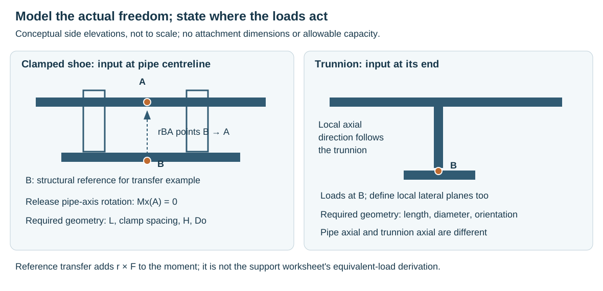
*Figure 11.8. Conceptual side elevations. The shoe assessment starts with loads at pipe centerline A. A trunnion assessment can start at its end B with axes defined along the trunnion. The reference offset is actual geometry, not a formula inferred from the symbol H. Clamped-shoe pipe-axis rotation is released. All other stated restraints still need their physical load paths.*
For a shoe, establish total length, clamp spacing or spacing between welded attachment areas, shoe height, nominal size and actual outside diameter. The spacing changes how a moment is distributed into clamp or weld regions. Height and diameter influence the offset between a pipe-centerline reaction and the structural attachment. Nominal diameter is an index to the correct product dimensions, not the measured outside diameter. Clamped and welded shoes can have different attachment spacing even at the same nominal size.
For a trunnion or structural dummy, establish its length, diameter, orientation, attachment and end connection, and identify where the input loads are defined. A load axial to a vertical trunnion is not axial to its horizontal parent pipe. In-plane and out-of-plane lateral loads also have different references. Select the relevant allowable direction and geometry range before comparing numbers. A long lateral lever can govern local parent-wall bending even where direct axial loading has greater capacity.
A simple reference transfer illustrates the distinction. With forces and moments expressed in the same Cartesian axes, moving a force/moment system from A to B gives:
$$\mathbf M_B=\mathbf M_A+\mathbf r_{BA}\times\mathbf F,$$
In this equation, $\mathbf r_{BA}$ points from B to A. Force is unchanged by translating the reference. Moment includes the additional lever-arm effect. If the assessment uses different local axes, rotate both force and moment components as well. This statics transfer does not supply the separate equivalent-load transformation of a support worksheet.
The support assessment then combines the supplied forces, moments and geometry into equivalent component loads for its applicable allowable comparison. Comparing only the original three forces can miss the equivalent demand created by bending moments. The calculation needs the correct load reference, axes, geometry, attachment arrangement and allowable table. Its transformations are part of that method, not an interchangeable sum of absolute force and moment values, which have different units.
Compare each transformed equivalent component with its applicable allowable; the resulting load fraction is dimensionless. The component check alone does not qualify the complete pipe, weld, anchor or foundation.
A moment entered in kN·m must first pass through the method's geometry-dependent conversion. It cannot be compared directly to a force allowable in kN.
The detailed worksheet derivation is not supplied here. The retained worked trunnion example has inconsistent axial/lateral allowable assignments and a reported maximum fraction that does not follow the printed table assignment. A worked shoe example labels a load fraction with a force unit. Those discrepancies prevent reproducing their reported acceptance as a verified result. Keep the component mapping and derivation unresolved rather than inventing a hidden equation or inferring that every trunnion is stronger than every shoe.
*Table 11.6. Support-detail functions and interfaces.*
| Detail family | Function to establish | Consequential interface |
| --- | --- | --- |
| Sliding shoe/rest | Carry weight while retaining intended travel and contact | Bearing length, friction, insulation height, wear and supporting beam |
| Clamp attachment | Carry specified forces without harmful slip or local damage | Grip, thermal loosening, corrosion, separation material and adjustment limits |
| Welded lug/shoe/trunnion | Transfer reactions through a qualified local attachment | Parent wall, weld/material, temperature, heat treatment and examination |
| Riser support with guides | Carry vertical weight and limit lateral response | Vessel/structure movement, local shell/clips and separate guide freedoms |
| Spring/hanger | Carry selected load through defined travel | Rate or constant effort, swing, calibration, settings, locks and empty state |
| Anchor/stop/guide | Restrain specified directions and loads | Pipe flexibility, dynamic reaction, common structure and actual gaps |
Equipment movement and sensitivity are developed in [rotating equipment](#chapter-c05) and [vessels, heaters and storage](#chapter-c06). The support choice must deliver the evaluated load path at those terminals.
Fireproofed steel also needs a structural attachment rather than a load carried by the fireproofing layer. Remove and restore the protection under the applicable procedure when attaching to the underlying member. Identification, dimensional detail, allowable load, material and surface protection should travel together into construction. A correctly fabricated bracket installed on an unsuitable beam is not a completed load path.
## Adapt the support to insulation and the material system
The opening metallic selection scope does not assign its spans, attachment rules or spring thresholds to polymer, RTR, glass-lined or cryogenic systems. The general questions of weight path, movement, contact and restoration remain useful, but local bearing and joining behavior need the qualified material-system basis. [Material selection](#chapter-c02) and [Joints](#chapter-c03) explain why those constructions differ.
For aboveground RTR, horizontal spacing is tied to the manufacturer's type, size and wall, operating temperature and liquid relative density. Add fitting and insulation weight rather than treating bare straight-pipe spacing as a finished arrangement. A supported aboveground procedure avoids point load by adequate bearing length. It provides 180° circumferential bearing with suitable elastomeric liners and protects against abrasion and excessive bending. Its vertical bonded collar can contact 360° of the pipe, with guides that restrain lateral response while allowing axial movement. Those are conditions of that RTR system procedure, which excludes underground, mechanical-joint and fire-water scope.
Thermoplastic systems can have lower and temperature/duration-dependent stiffness, substantial thermal movement and vulnerability to sharp contact or abrasion. HDPE can be flexible enough to require a different spacing and handling arrangement from rigid steel. PVC/CPVC and other families have their own limits. Heavy metallic valves should have a load path that does not make the nonmetallic pipe carry an unqualified concentrated weight. Joining and cure conditions also matter during lifting or erection. A support scheme must not impose loads on a joint before its prescribed ready condition.
Lined and glass-lined steel retain a metallic structural boundary but impose constraints on heating, welding and contact that ordinary bare-pipe details do not address. Clamp-on or supplier-qualified support arrangements can avoid damage to the liner. The clamp's own grip, corrosion and local load still need evaluation. Avoiding a weld is one part of the choice, not its completion.
For insulated metallic piping, distinguish the bearing load path from the thermal and vapor-barrier functions. Load-bearing insulation must have the specified capability, and sliding or restraint forces must enter the intended hardware without crushing the insulation or tearing the barrier. Cold bridges and protrusions can cause condensation or ice even where pipe stress is satisfactory. [Insulation and thermal protection](#chapter-c14) carries the material and barrier detail.
One cold-insulated metallic trunnion procedure specifies an insulated length $L_i=T+3t$. In this equation, $T$ is line-insulation thickness and $t$ is trunnion-insulation thickness. At least 150 mm of uninsulated trunnion follows.
If that required length cannot be provided, the procedure calls for complete cold insulation of the trunnion or a cold-insulated support. This conditional detail method does not establish a cryogenic support or thermal design.
At small-bore vents, drains and instrument roots, support must preserve connection integrity and intended communication. A brace tied to stationary steel can oppose the parent line's growth. A support following the line can have different response. Added valves or longer insulation extensions change mass and lever arms. [Small-bore connections](#chapter-c07) develops the attachment and fatigue evaluation.
For relief and slug-flow piping, supports at direction changes must carry evaluated reaction loads while retaining appropriate movement. A static weight-only detail is insufficient.
A cold-insulated support can also govern erection sequence. In one adopted outer-clamped insulation-system procedure, field insulation at joints is installed after pressure testing, while the supports must already carry the line during erection and testing. Consequently, those field-insulation locations are kept away from the support positions. Leaving the support to be completed after the test would remove a required test-state load path.
The same procedure requires at least 50 mm clearance between insulation and supporting structure while accounting for movement. It checks friction load against the insulation’s load-bearing capacity. If an outer clamp cannot transmit the evaluated anchor or stop reactions, the procedure calls for a specially designed arrangement. That arrangement may use matching-material welded attachments and a qualified insulating load-transfer block.
This alternative changes both structural and thermal interfaces. It is not permission to crush ordinary insulation or omit the vapor barrier. These are conditions of that cold-insulated support procedure, with material-system and cryogenic suitability established separately.
## Establish the empty-line condition before releasing a spring
A spring selected for a filled line can exert an unfavorable force when the line is empty. Where the empty-line assessment identifies that risk, the installation procedure can require locking until actual service fluid is present, with a specific warning against empty conditions. Define the filled condition permitting release and how release is checked. Removing every lock immediately after testing can defeat that requirement.
During hydrotesting, use the actual liquid weight, pressure-thrust boundaries and any spring-blocked configuration. Permanent supports must carry that case unless designed temporary supports are provided. Evaluate the pipe, hardware, receiving structure and equipment interface in that load path.
## Installation and testing must preserve the analyzed configuration
Verify locations/attachments, guide/stop directions, cold and operating clearances and maintenance access. Tight guides, dirty sliding surfaces and shoes able to travel off their beams can defeat the analyzed behavior even when coordinates are correct.
Field-adjustable supports help accommodate tolerances and differential settlement, but their adjustment must be controlled. Set field-welded supports correctly before completing the pipe attachment. Identification on the hardware and drawing allows an installer or later maintainer to connect the actual device to its load, travel and setting. Spring cold and hot marks are useful only when their reference condition is understood.
A cold mark may refer to an ambient line filled with actual service fluid. For tank piping it also assumes an empty tank with zero settlement. The hot mark for that tank case includes filling and settlement. Empty pipe is not interchangeable with this defined cold condition.
Intentional cold spring also needs to be distinguished from forcing a misaligned assembly into place. Cold spring deliberately changes installed geometry to redistribute forces between cold and hot conditions. The specified amount and fabrication tolerances therefore matter. Although cold spring can redistribute forces near rotating equipment, a project prohibition on that use without owner approval remains controlling. Resolve permission and the analyzed prestressed geometry before specifying it. An adjustable support or a construction spool can accommodate erection tolerances without silently introducing a different prestressed geometry.
Spring shipping locks preserve a preset position during transport and installation, while test blocking may serve a different temporary load purpose. The applicable construction procedure must define their removal sequence. A procedure may retain locks through hydrotesting and insulation, with the empty-line exception described above. A different procedure may relate removal of gags and spacers to completion of pressure testing and/or product filling below 100°F. It may call for dimensional adjustment before release.
These sequences must be resolved in the selected installation instructions and manufacturer's requirements. They should not be merged into a new universal temperature or release rule.
Test preparation should define the boundary, fluid, fill and vent points, drain points, isolation devices and temporary support configuration. Vertical extent also matters. The static head must not create pressure above the allowable test pressure at a low point. Piping must be properly anchored and guided before testing, and applicable tie rods must be in the required test position.
Temporary supports and restraints need identification sufficient to ensure their controlled removal. The test pressure, hold time, fluid chemistry and personnel protection belong to the applicable test procedure. Support adequacy alone does not establish a complete test specification.
After acceptance, depressurization and draining lead to restoration, not directly to service. To restore the arrangement:
- Remove test blinds, temporary spools and supports as specified.
- Replace removed items in the correct positions.
- Verify mechanical completeness.
Spring restraints require the condition-specific release decision, rather than indiscriminate removal alongside all temporary items. After restoration, reevaluate the operating arrangement. The designed guide paths, sliding surfaces and spring freedom must actually exist. Record the test configuration and final configuration so that commissioning does not inherit an undocumented temporary load path.
## Maintenance and modification reopen the affected load paths
Maintenance access is part of the support problem. A compressor connection that must be removed needs a practical break-out arrangement in addition to the nozzle flange. A strainer or valve removal can alter the connected assembly. Access for lifting and withdrawing those components must be planned together with support locations. Before disconnecting a heavy item, determine how the remaining pipe and the item itself will be carried. The operating support arrangement is not proof that a partly dismantled arrangement is stable.
A replacement valve, thicker insulation, a rerouted branch, a changed operating temperature or settlement changes the assumptions on which support reactions were calculated. An added restraint intended to cure vibration may block thermal movement. Removal of a guide for access may permit a different dynamic response. Repair and modification therefore require review of the affected states and interfaces, not only the replacement component's pressure rating. When the proposed work changes a restraint or load, revisit the neighboring spans and equipment reactions and the structure receiving the changed load.
Compare observed contact, travel and spring indication with the expected empty/filled, cold/hot or blocked state. Inspect attachment condition, corrosion protection, sliding surfaces, insulation and receiving structure. Unexpected lift-off, spring position or vibration requires investigation before adjustment, under the project’s inspection interval, acceptance tolerance and repair authority.
Preserve evaluated conditions and restraint functions, spring loads/travel, nozzle/structural limits, settings and special warnings, temporary test arrangements and restored condition. Drawings and calculations must distinguish deliberate movement freedoms and empty-line blocking from defects or forgotten shipping locks.
# Chapter 12 — Buried piping, pipelines and offshore interfaces
## Define the system before choosing its route
Piping below grade is not one engineering system. A plant oily-water sewer collects distributed drainage and depends on its internal elevations. A buried cooling-water header distributes pressurized water and must remain isolatable and repairable. A transmission pipeline connects facilities across a route whose terrain, population, crossings and operating inventory matter. An offshore riser connects that route to a moving, loaded structure through a severe marine environment.
Define the service boundary, endpoints and connections, pressure sources, receiving systems and physical environment before selecting hydraulic, structural or intervention methods. A pressure-rated line can still fail its function through an undrainable route, undermined foundation, excluded inspection tool or unassessed installation state.
This chapter keeps plant underground systems, transmission pipelines and offshore facilities/rigid metallic risers distinct. [Utility architecture](#chapter-c12) establishes collection, segregation and delivered service. Here the route and physical configuration must make those functions possible. [Mechanical evaluation](#chapter-c09) and [supports and restraints](#chapter-c10) explain general load and movement methods. The environmental and installation interfaces developed here supply their actual inputs.
## Lay out the underground plant as an accessible network
Plant gravity drainage begins with what can enter the system and where it may go. Storm runoff, contaminated surface water, oily equipment drainage, chemical wastes and sanitary drainage have different collection and treatment requirements. Combining oily and storm drainage can save pipe while enlarging treatment duty and requiring suitable segregation against vapor or fire propagation. Separate chemical collection may be justified by material compatibility, recovery or neutralization. The preferred combination depends on the actual plant and receiving facility.
- Map the paved and unpaved catchment areas, curbs/dikes, equipment drains, continuous discharge and credible rain/fire-water cases.
A catch basin collects surface liquid and can include a sediment trap and an outlet seal. A drain hub collects an intended equipment discharge. Branches lead into sublaterals, laterals and a main. Sewer boxes and cleanouts provide access to otherwise hidden sections. Their positions must permit actual cleaning and inspection, not merely appear as symbols on the drawing.
Seals address communication through a drainage network. Under an arrangement using water seals to limit vapor/fire spread, determine which connections enter through a seal, the maintained seal depth and the behavior when flow or liquid inventory changes. Off-site straight-through mains can have different conditions from plant laterals entering a box. A seal or covered box does not itself establish an atmosphere suitable for entry.
- Locate access, covers and any required vent destination with the service hazard and intervention in mind.
- Prepare a below-grade obstruction plan while the plot remains adaptable.
- Include foundations and their depths, existing lines, electrical/instrument ducts, trenches, light-pole bases, roads, paving and future connections.
- Establish outlet and battery-limit invert elevations early.
An apparently convenient upstream route may be impossible once its downstream destination is fixed. Surface grading, catchment subdivision and collection points must be developed together so equipment foundations or access ways do not divert water away from the intended basin.
Material selection includes fluid, temperature, pressure, joining, burial and external loading. Metallic piping, iron drainage systems, concrete, vitrified clay, polymers and reinforced resin systems differ in wall dimensions, joints and resistance to handling or ground loads. A material that resists a corrosive drain may still need a particular buried support and joining design. [Materials](#chapter-c02) and [installation](#chapter-c17) carry the detailed family rules. A metallic pressure-pipe detail is not a universal buried-drain detail.
## Keep secondary containment a usable second boundary
A buried drain carrying contaminants can need an arrangement that detects and collects leakage before it reaches surrounding soil. One alternative is a primary carrier pipe within a secondary containment pipe. Another can move the discharge to a pressurized aboveground route to remote treatment. They have different pumping, visibility, access and operating consequences.
- Select the actual required containment and emissions function before choosing the hardware.
In a double-containment assembly, the carrier conveys the intended fluid and its supports maintain the required position within the outer line. The outer pipe has a separate leaked-fluid/vapor collection function. FRP, lined or polymer assemblies may be prefabricated with internal supports, but the material, joints and handling must preserve both boundaries. A carrier joint that passes inspection does not establish the secondary joint, penetration or collection path.
Sewer-box transitions need particular care. The carrier penetrates a wall while the secondary barrier continues across the pipe/box interface.
- Provide a defined means of draining collected leakage and detecting vapor where required, with access to clean the collection line and inspect the barrier.
A small detector line connected at the wrong location or a collection pocket that cannot be emptied can leave the second boundary present in the drawing but ineffective in service. Permanent and portable detection arrangements have different observation and maintenance demands.
A below-grade trench is another physical arrangement from a directly buried line. Insulated or traced piping, valves and drains can remain accessible within it, but trench width, cover type, traffic, drainage and service exposure must suit the work performed there. Electrical/instrument ducts and pull points also need reserved space: a duct exit that later becomes covered by piping or a maintenance laydown area can lose its required access.
- Complete the underground composite with the actual drain points, line/reference elevations, joint/terminal details, crossings, foundations, duct space, cover, box schedules and new-to-existing interfaces.
Before covering the installation, verify the connections and recorded route against that arrangement. The carrier, secondary barrier and any detection/collection system must retain their intended separate functions through testing, restoration and later repair. [Construction](#chapter-c17), [readiness](#chapter-c18) and [technical records](#chapter-c21) carry the general methods.
### Trace carrier flow, collection and observation through the interface
Trace carrier fluid separately from leakage/vapor entering the secondary space. Sensors require their specified observation conditions; removal requires a communicating drain to a suitable destination. Neither supplies the other function or a seal.
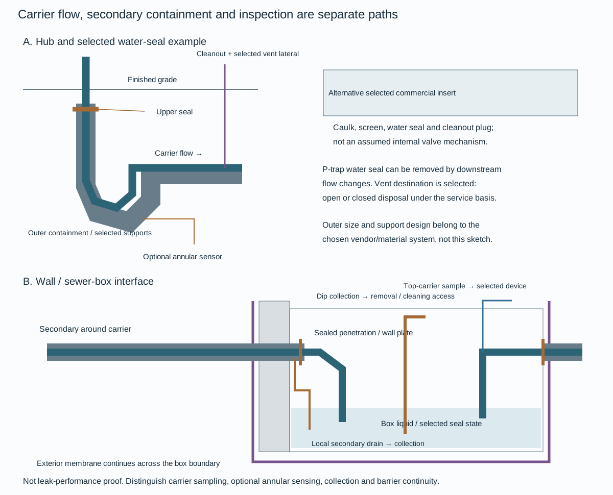
*Figure 12.1. Selective functional sections derived from drain-hub and sewer-box arrangements. Carrier flow is distinct from the outer containment, hub upper seal, wall seal/plate and exterior membrane. The box's local secondary drain, dip collection line and top-carrier sampling connection have different endpoints. A separate optional annular sensor is shown at the hub. The commercial water-seal insert is an alternative, not an invented internal valve. These sketches carry no default pipe sizes, collection capacities, leak-tightness guarantee, detection coverage or regulatory compliance result.*
At a hub, the carrier can pass through a P-trap while the outer pipe encloses the connection. An upper carrier/secondary seal terminates the annular boundary. That upper seal is distinct from the liquid vapor seal maintained by the trap.
- Select the position and construction for the real fluid level and containment duty.
The carrier-positioning supports and outer pipe size belong to the chosen prefabricated vendor/material system. FRP, lined and polymer combinations have different joint, support and handling requirements. A typical sketch supplies neither generic support spacing nor a substitute for the two-boundary construction checks.
A water seal can be lost when variable downstream flow withdraws it. Vent communication therefore belongs with the selected carrier/cleanout arrangement. The vent lateral shown in the functional section communicates with the drain path through the cleanout connection and needs its seals and accessible plug.
- Select an open or closed disposal destination under the service and emissions basis.
An open arrow on a layout is not permission to release a contaminant. A running trap, sewer-box seal or selected commercial hub insert is a different alternative. The insert arrangement includes caulking, a screen, water seal and cleanout plug, with debris-removal access. No additional internal mechanism is inferred.
At a sewer-box wall, the carrier penetrates a separately sealed outer assembly. A wall plate and the exterior polyethylene membrane example address different barrier interfaces. The local drain from the secondary side provides a route for material entering that space. A dip collection line reaches the box's lower liquid region and remains accessible for removal and cleaning. The box can also receive the intended carrier effluent.
A collection path does not, by itself, guarantee segregation of a leak from that effluent or establish adequate collection/storage capacity. The adopted receiving and removal method must match the actual material and state.
Observation paths need their own endpoints. The top-of-effluent-carrier sampling connection through the box top permits attaching a portable device for periodic checks or installing a separately selected permanent arrangement. It is distinct from an optional sensor located in the hub's annular space. Sampling the carrier does not automatically monitor the entire annulus, and one sensor does not prove coverage of every joint, pocket or box penetration.
- Retain the device's selected location, access, response basis, periodic or continuous observation duty and maintenance requirements with the installed assembly.
Before covering or restoring the system, verify both boundaries, the sealed penetrations, support positioning, collection communication and accessible inspection/cleaning paths. A changed carrier route or seal can alter where a leak collects. An inaccessible cleanout or blocked local drain can defeat an otherwise intact drawing.
- Preserve the installed geometry and separate barrier, collection and detection evidence through later repair.
These interfaces explain the containment functions. They do not establish complete leak performance or satisfaction of a current environmental requirement.
## Preserve the invert and account for the outside envelope
The invert is the elevation of the inside bottom of a gravity line. It is a useful constant across pipes whose wall thicknesses differ. A construction dimension to centerline or outside bottom needs an explicit conversion. Maintaining the wrong reference can create a step inside the drain or miss a crossing clearance.
For a circular pipe with internal diameter \(D_i\), wall thickness \(t\) and invert elevation \(z_i\), consistent geometrical relations are
\[
z_{CL}=z_i+\frac{D_i}{2},\qquad
z_{OB}=z_i-t,\qquad
z_{OT}=z_i+D_i+t.
\]
\(z_{CL}\), \(z_{OB}\) and \(z_{OT}\) are centerline, outside-bottom and outside-top elevations. All elevations and dimensions use m on one datum. The relations assume a circular section with the stated wall thickness. Sockets, hubs, insulation or another local envelope need separate clearance checks.
For a uniform downward invert grade \(s\) over horizontal distance \(L\), the downstream invert is \(z_{i,2}=z_{i,1}-sL\). Grade is dimensionless when fall and horizontal distance use the same units. A slope stated for a particular chemical drain or sewer procedure must stay with that arrangement. It is not a minimum for every liquid line.
At crossings, apply required separation to the actual outside/joint envelope, allowing for excavation, settlement and construction tolerances.
A reducer or a change of material can change the relationship between the outside envelope and the invert.
- Follow the internal bottom through the joint and fitting, with the applicable bell/spigot orientation and available reducer pattern.
An internal projection can retain solids or create a weir. An invert schedule should therefore carry actual pipe dimensions and fitting transitions, rather than use nominal size as though it defined every internal surface.
### Coordinate excavation, foundations and the line that can move
Gravity routing consumes elevation as it proceeds. A pressurized water line can often rise or fall locally to clear it, whereas introducing an arbitrary rise in the sewer can destroy its intended gravity path.
- Use that difference when allocating crossing space.
A lift station is another arrangement, with pumping, power, overflow and maintenance duties. It should be selected deliberately rather than hidden in an unworkable gravity profile.
Spread footings depend on the supporting soil. A route outside the footing in plan may still require an excavation that removes that support at depth. A simple 45° exclusion sketch appears in one layout basis, but it is a scoped preliminary coordination aid, not a geotechnical rule for all soils or excavations.
- Establish the actual foundation/soil/excavation condition and evaluate the alternatives: reroute the line, change elevation, revise the foundation, or provide the required excavation support.
A pile-supported foundation changes the load-transfer problem. It does not eliminate every excavation, access or buried-service concern.
Pressure-water routing can preserve rack space and shorten exchanger laterals when headers are close to channel ends. Aboveground routing improves direct access but can enlarge racks and branches. Buried hot return and cool supply also interact through soil heat transfer. Leave practical space for joints, tools and future excavation while maintaining channel removal, roadway and electrical-duct access. The most compact initial drawing may have the largest repair cost once the line is covered.
Fire-water loops and section valves need a configuration that preserves the required coverage during repair or isolation. Cooling-water supply/return and potable connections must retain their distinct functions.
- Plan the below-grade-to-aboveground transition, the applicable joint and terminal elevation, supports and the division of installation responsibility.
A bevel end or buried flange at the agreed interface is part of the installed arrangement, not an unresolved drawing handoff.
## Calculate drainage duty and hydraulic state together
For a rational runoff estimate, a useful SI expression is
\[
Q_r=\frac{i\,C\,A_c}{3{,}600}\quad\text{in L/s},
\]
In this equation, rainfall intensity \(i\) is in mm/h. Catchment area \(A_c\) is in m², and runoff coefficient \(C\) is dimensionless. The conversion follows from rainfall depth times area: 1 mm over 1 m² is 1 L.
- Add the applicable continuous process drainage on the same flow basis.
The coefficient represents the selected catchment behavior. It does not account for every obstruction, temporary blockage or receiving-system constraint.
One adopted drainage procedure uses runoff coefficients 0.9 for paved and 0.5 for unpaved areas, with a 1.1 sizing factor on combined rain/process flow. That factor is not an independent 10% rainfall depth on each term. The procedure evaluates rain/process flow at 75% full and fire-water/process flow at full flow. Retain the fill-state criterion and actual plant rainfall/fire-water basis; the larger numerical flow alone does not complete pipe selection.
Fixed allowance values used in a particular layout example are not a substitute for a deluge or emergency-demand assessment.
The Manning uniform-flow method relates capacity to area, hydraulic radius, roughness and energy gradient. Expressed on an SI dimensional basis,
\[
v=\frac{1}{n}R_h^{2/3}S^{1/2},\qquad Q=A_fv,\qquad R_h=\frac{A_f}{P_w}.
\]
In these equations, \(v\) is mean velocity in m/s. \(Q\) is flow in m³/s, and \(A_f\) is flowing area in m². \(P_w\) is wetted perimeter in m, and \(R_h\) is hydraulic radius in m. \(S\) is the dimensionless energy gradient. For the assumed uniform gravity-flow state it is taken equal to pipe grade.
\(n\) is the conventional Manning roughness parameter, with s/m\(^{1/3}\) as the dimensional basis of this SI expression. The model does not resolve a backwater, surcharge, abrupt junction or an entire transient network merely by inserting the floor slope.
For a circular full section, \(A_f=\pi D_i^2/4\) and \(R_h=D_i/4\). Roughness, solids, joints and maintained internal condition affect performance; a clean/coated chart basis is not an aging-line assessment.
The 75%-full rain case needs the partially filled circular area and wetted perimeter. It is not established by multiplying full-flow capacity by 0.75: the hydraulic radius changes too. For a circular segment of liquid depth \(y\), its geometry can be expressed as
\[
\theta=2\cos^{-1}\!\left(1-\frac{2y}{D_i}\right),\qquad
A_f=\frac{D_i^2}{8}(\theta-\sin\theta),\qquad
P_w=\frac{D_i\theta}{2}.
\]
Depth and diameter use m, and \(\theta\) is the wetted central angle in radians. This is geometric construction of the assumed circular flowing section, not another empirical hydraulic criterion. Identify the governing fill convention before interpreting a percentage. Verify velocity/self-cleaning and receiving-boundary conditions for the complete network.
Low operating flows also matter. A line sized for a large emergency event can retain sediment at ordinary drainage duty. The [structured teaching calculations](assets/C11/c11-methods.json) preserve the inputs, results and limitations without selecting a plant pipe size.
## Define the transmission pipeline and its operating envelope
A transmission pipeline connects facilities over a route. Under one specifically adopted pipeline definition, it extends from pig trap to pig trap, including their pipework/valves, or to the designated first isolation valve where no trap is fitted. The connected plant equipment remains outside that defined pipeline boundary. Flowlines from off-plot wellheads can fall inside it, while piping within a producing facility has its own equipment, layout and pressure-design context.
- Draw and retain the actual code and engineering interfaces rather than assign scope by distance or pipe diameter alone.
Within a producing facility, removable piping around wells can preserve workover space, and planned future connections can avoid later interruption of a crowded operating area. Supports must prevent unintended liquid pockets and equipment connections need their flexibility/misalignment assessment. Those facility duties do not disappear when a connected off-plot flowline is assigned to a pipeline boundary.
The governing code edition, fluid category, jurisdiction and adopted supplements must be established for that boundary. One example pipeline procedure supplements the 1992 editions of ASME B31.4 and B31.8 with its adopted amendments. It classifies a fluid at ambient temperature and atmospheric pressure plus 0.5 bar, rather than solely by its transported phase. Its groups A/B have vapor pressure below 1.5 bar absolute at ambient temperature: A is nonflammable, stable and nontoxic. B is flammable, unstable or toxic.
Groups C/D have vapor pressure above 1.5 bar absolute: C is nonflammable, stable and nontoxic. D is flammable, unstable or toxic. Under that particular procedure, A/B use its B31.4 route and C/D its B31.8 route. Its explicit amendment places LPG and anhydrous-ammonia transmission in its B31.8 route even while noting their B31.4 coverage. That is a particular adopted classification/assignment, not a new universal rule for those products.
It should remain an explicit alternative wherever that practice governs.
- Establish pressure and temperature profiles for steady and transient conditions over the projected life.
Maximum throughput and turndown can create different duties. Low flow can permit water dropout, deposits or changed inhibitor distribution. High velocity can increase erosion or disrupt protective films. Shutdown, startup, pigging and flow changes can move liquid inventory toward downstream equipment. A pressure calculation at one nominal flow does not describe all these states.
For a liquid route, hydrostatic head and friction can change which location governs pressure. Designing different route sections for different pressures requires assessment of credible adjacent-section overpressure. In a gas route, pressure segmentation can also reduce useful line-pack flexibility. [System conditions](#chapter-c01) and [pressure protection](#chapter-c08) develop the general distinctions. The route establishes where they have to be applied.
The operating philosophy supplies practical inputs: staffed or remote operation, communications, access, pigging purpose/frequency, maintenance bypasses, integrity monitoring, foreseeable shutdown and final abandonment. These decisions affect physical hardware and route long before handover. A continuously required line needs a deliberate means of servicing a component that cannot remain in operation. An unplanned temporary bypass is a changed piping configuration with its own basis.
## Choose the route with construction and intervention in view
A route survey has different tasks onshore and offshore. Onshore work needs topography, roads/railways/rivers, occupied buildings and future development, soils, subsidence, resistivity and environmental conditions. Offshore work adds bathymetry, rock/coral features, seabed properties, currents/waves, fishing/shipping activity, other installations and concession constraints. The survey should identify the features that construction must preserve or reinstate as well as the geometry on which the analysis relies.
Population/location classes and separation assessments affect particular pipeline design bases. They must stay attached to the applicable fluid/code scope. Neither a sparse route nor a low nominal pressure eliminates every release consequence.
- Consider emergency access and the environmental sensitivity of a release along the whole route, including places that are difficult to reach or isolate.
Route curvature, crossing angle and spacing interact with the installation method. A gentle foundation route may be followed by elastic bending, while sharper changes require a specified field/hot bend and its qualified geometry. An offshore crossing chosen only for minimum distance can conflict with installation, anchoring or future access. Approaches to a platform need space for tie-in and construction vessels and protection from marine activity. Shore and major-river transitions require a defined construction/environmental boundary.
Pipelines in permafrost or arctic conditions need considerations outside the ordinary route basis described here.
Soil and water participate in mechanical behavior. Burial can restrain expansion, alter load distribution and hide corrosion or movement. Subsidence, landslide, scour and seabed settlement impose a changed configuration. An offshore pipe can develop free spans. Weight/buoyancy and hydrodynamic loads affect stability.
Ground contours, crossing protection and cover are therefore analysis and inspection inputs, not only civil dimensions.
### Use an initial route screen before completing the risk assessment
An initial occupied-building route screen requires fluid classification, pressure and geometry. Final assessment still needs failure likelihood, release/ignition, population and exposure over the line’s life, plus crossing and emergency-access consequences.
One historical pipeline planning method provides two unit-bound expressions. With design factor not exceeding 0.72 it uses
\[
d=Q_f\left(\frac{D^2}{32000}+\frac{D}{160}+11\right)
\left(\frac{P}{32}+1.4\right).
\]
For the method's design-factor category not exceeding 0.4 it also provides
\[
d=Q_f\left(0.7-\frac{t}{21}\right)(P+82).
\]
In these expressions, \(d\) is distance in meters. \(D\) is pipeline diameter in mm, and \(t\) is wall thickness in mm. \(P\) is maximum allowable operating pressure in **bar gauge**. \(Q_f\) is the method's dimensionless fluid factor, distinguished here from volumetric flow. The numerical coefficients contain this empirical unit convention.
Metres, MPa or psi cannot be inserted without transforming the method. Its design factor is the ratio of pressure hoop stress at design pressure to specified minimum yield strength, not a general safety multiplier.
Within this planning basis, take \(D=150\) mm when diameter is smaller and \(P=20\) bar gauge when operating pressure is lower. Thickness below 9.5 mm **may** be represented by 9.5 mm. Thickness above 13.5 mm **shall** be represented by 13.5 mm. These are input conventions of the screen rather than changes to installed wall. The fluid factors are 0.3 for its category C.
Within category D, they are 0.5 for methane, 0.8 for ethylene, 1.0 for LPG, 1.25 for NGL, 0.45 for hydrogen and 2.5 for ammonia. Its categories A/B carry zero factor under this particular building-distance method, while construction and operating access remain required. Zero factor does not remove other hazards or create a zero-separation rule for another service or design basis. The [structured route method](assets/C11/c11-pipeline-methods.json) keeps the definitions and category conditions together.
The two written design-factor inequalities can overlap. Establish the applicable expression under the adopted basis; do not select the smaller distance solely for that overlap.
Unknown-fluid analogy also requires the actual hazard basis, rather than choosing the smallest quoted factor. Final routing follows the quantitative risk assessment and applicable requirements. The screen alone does not approve an occupied-building setback.
## Make protection inspectable and retain its distinct mechanisms
External coating limits environmental contact. Cathodic protection addresses exposed metallic areas within its electrical and environmental conditions. Under an adopted metallic buried-pipeline basis, both can be required, with electrical isolation and monitoring provision arranged so their effectiveness can be demonstrated. Offshore submerged, splash-zone and atmospheric portions have different protection duties. More cathodic potential is not automatically better: excessive protection can introduce hydrogen-embrittlement concerns in susceptible material.
- Protect coating during storage, handling, lowering and backfilling, and provide the required field-joint restoration/inspection.
A coating selected well in design but cut by handling or damaged by backfill changes the installed corrosion basis. Support contacts and insulated sections need arrangements that avoid retained moisture and permit inspection. [Coatings and corrosion management](#chapter-c15) explains selection/application methods. The route and construction states determine their local exposure.
Internal corrosion depends on the transported fluid and its flow regime. Water, deposits and inhibitors may reach different locations as throughput declines. A probe or coupon can give local evidence without proving the entire line's condition. Pig debris is qualitative evidence rather than a general corrosion-rate measurement. Where the operating basis requires full-route internal assessment, inspection-tool access and geometry must have been provided.
[Operating integrity](#chapter-c19) develops the assessment and response. This chapter establishes the physical access.
Internal coatings, linings and corrosion-resistant pipe are different alternatives. A coating with holidays cannot be credited as complete prevention of corrosion. A lining needs compatibility and continuity at joints, and gas permeating into an annulus can create a collapse problem when the line is depressurized unless relieved by the evaluated arrangement. Nonmetallic and flexible pipelines can be useful for specific services, but their joining, restraint, collapse and testing rules need their own basis. The rigid metallic rules developed later are not silently extended to them.
Isolation divides inventory and separates a route from a plant incident. Sectionalizing valves address line releases along a route. An emergency valve at a facility interface has another role. Closure and leak detection should be assessed for actual consequences, available actuation and the contained inventory, rather than infer complete leak-tightness from a valve symbol. Blowdown introduces temperature, discharge and access conditions of its own.
Control pressure and protective pressure limits also differ. A regulator maintaining normal inlet pressure does not by itself protect the pipeline against its failure. Credible source overpressure, surge after valve closure and thermal expansion of trapped liquid require their appropriate evaluation. The maximum transient pressure can occur upstream of the initiating closure, especially in a hilly liquid route. Defined allowable operating and incidental pressures have different frequency/duration bases.
They must be assessed at every consequential location.
### Carry pressure, restraint and shear into the pipeline stress question
Wall derived from pressure hoop stress still has to carry longitudinal and shear demands under the actual functional and environmental loads. The restraint representation changes the longitudinal stress: the fully restrained thermal case is different from a free-expansion case carrying bending. A pipe with partially mobilized soil resistance, a flexible spool or changing contacts cannot simply inherit either limiting expression as its complete model.
One adopted historical pipeline stress method combines components as
\[
S_{eq}=\sqrt{S_h^2+S_L^2-S_hS_L+3S_s^2},\qquad
S_h=\frac{PD}{2t}.
\]
Its limiting longitudinal expressions are
\[
S_{L,r}=\mu(S_h-P)-E\alpha(T_2-T_1),\qquad
S_{L,u}=\frac{S_h}{2}+\frac{M_b}{Z},
\]
These expressions apply to fully restrained and fully unrestrained pipe respectively. Its combined shear expression is
\[
S_s=\frac{\mathcal T}{2Z}+\frac{2F_s}{A}.
\]
Use one consistent dimensional basis:
- \(P\) and stresses in MPa (N/mm²).
- Diameter \(D\) and wall \(t\) in mm.
- Modulus \(E\) in MPa and thermal coefficient \(\alpha\) in K⁻¹.
- Installation-to-operation temperature difference \(T_2-T_1\) in K or °C difference.
In these expressions, \(\mu\) is Poisson's ratio. \(M_b\) is applied bending moment, and \(\mathcal T\) is applied torque, both in N·mm. \(Z\) is pipe section modulus in mm³. \(F_s\) is shear force in N, and \(A\) is pipe-wall area in mm². The signed longitudinal component is retained in the equivalent-stress cross term.
- Do not substitute a fluid area for the pipe-wall area or insert nominal size as though it were the required diameter.
The [component method and examples](assets/C11/c11-pipeline-methods.json) preserve these quantities.
Nonzero torque or shear adds another component and must use its actual load/sign combination.
Under that method, operational calculations use nominal wall **excluding corrosion allowance**. Installation, hydrotest and operation have separate functional/environmental combinations and local equivalent-stress fractions of yield: 96%, 100% and 90%, respectively. Its installation provision explicitly excludes methods in which yielding is integral, including reeled pipe and rigid riser pull-in through a J-tube. These historical fractions do not qualify a new project or replace checks for collapse, fatigue, local attachment demand or a strain-based installation method.
[Mechanical evaluation](#chapter-c09) establishes the real restraint/contact and load representation. This method shows how that representation reaches a pipeline component-stress calculation.
## Give pigging hardware its intended operating functions
A pig trap allows insertion/launch or receipt/retrieval of a pig while the connected system follows its defined operating arrangement. The barrel contains an enlarged major section for loading or removal, a reducer, a minor section and an end closure. Actual internal clearances matter: nominal barrel oversize can be consumed by wall thickness, fittings or the inspection tool's geometry.
The connecting lines have different functions:
*Table 12.1. Pigging connection functions.*
| Connection or item | Function that the arrangement must establish |
| --- | --- |
| Facility bypass | Continue the selected pipeline/facility flow path |
| Kicker line | Divert fluid through the barrel for launch or receipt; connection position depends on trap direction/type |
| Balance line | Fill/pressurise both sides of a pig without unintended motion |
| Pressurising line | Control filling or pressure equalisation where required |
| Drain points | Remove and verify accumulated liquid, including trapped regions near a pig |
| Vent/blowdown points | Relieve/purge the relevant spaces, including a region isolated by a stuck pig |
| Thermal relief | Protect a trapped-fluid pressure case |
| Pig signaller | Give location/pass evidence at its actual installed point |
*The structured [pig-trap function table](assets/C11/c11-pig-functions.json) preserves these purposes and the geometry/condition qualifications. This is not a valve-operating sequence.*
A launcher kicker located toward the closure and a receiver kicker toward the reducer do not perform identically. Bidirectional arrangements require their own selected connection design. A balance connection can prevent a loaded pig moving into a valve or losing its seal as the barrel fills. A small pressurizing bypass can permit controlled equalization but must not defeat a required shutdown boundary. The location and control functions should be drawn coherently instead of assigning one generic branch to every purpose.
Drain and vent placement must reach both sides of a potentially obstructing pig. A tell-tale drain gives evidence that liquid has been removed. Drain diameter, slope and sphere position also affect blockage. A vent near the closure alone may not depressurize the region behind a pig stuck in the minor barrel. Pig traps can contain air or air/hydrocarbon mixtures during intervention, so a flare connection needs that composition case as well as its ordinary pressure duty.
The receiving drain can be exposed to blow-by; [collection architecture](#chapter-c12) and [protection](#chapter-c08) remain connected to the physical trap.
### Draw the connections around the spaces a pig can isolate
The facility bypass joins the main tee to the adjoining facility boundary. The kicker diverts fluid between that bypass and the major barrel. The balance line branches from the barrel side of the kicker path to the minor barrel near the trap valve. This makes simultaneous filling and pressurization of the two sides of a loaded pig a distinct function from the main diverted-flow path. A separate small pressurizing bypass around a kicker valve can serve controlled equalization where that arrangement is adopted.
It is not a replacement for the balance connection across the pig.
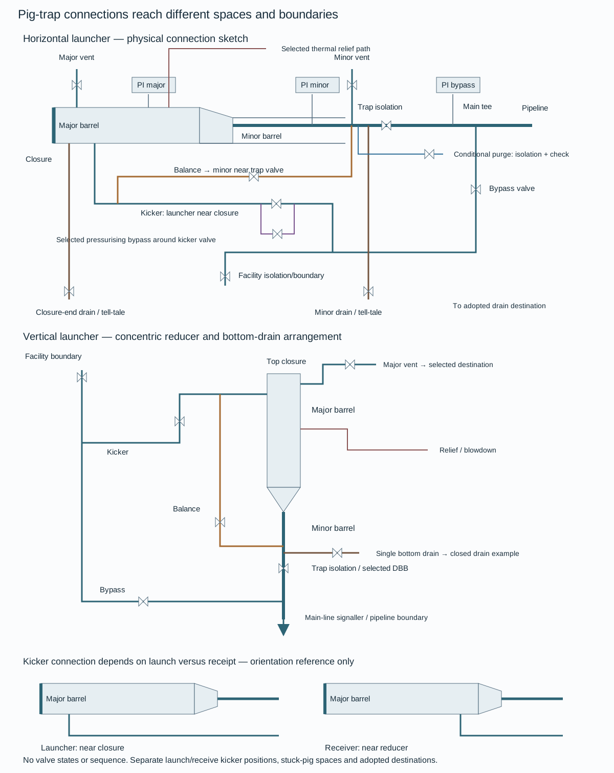
*Figure 12.2. Functional horizontal and vertical launcher views, with a launcher/receiver kicker-position inset. The horizontal view retains major and minor vents, drains, pressure indications, a conditional purge connection, thermal-relief path and pressurizing bypass. The vertical view shows the concentric reducer, lower drain and selected vent/relief destinations. Valve symbols identify hardware interfaces and imply no open/closed state or operating sequence. These are connected functional views, not complete P&IDs, shutdown logic, capacity calculations or isolation proof. [Structured endpoints, conditions and boundary roles](assets/C11/c11-boundary-paths.json) and the [native drawing implementation](assets/C11/c11-boundary-paths.draw.py) keep the distinctions recoverable.*
- Consider a pig lodged in the minor barrel.
A vent connected only near the end closure communicates with the closure-side volume. The pig can obstruct communication with the volume near the trap valve. The horizontal arrangement therefore retains a vent on the minor side as a separate pressure-release path, together with the corresponding pressure indication. Drains near both ends address liquid pockets rather than prove gas pressure is relieved. A tell-tale connection supports checking the liquid state but does not demonstrate that every trapped compartment is empty or depressurized.
A blocked tapping or shut branch changes the actual connectivity represented by the sketch.
Orientation changes the physical endpoints. In the depicted horizontal method, drains connect at the bottom, while vents, pressure indications, relief, purge and signaller connections occupy the top quadrant. Kicker, balance and bypass connections use a side position or a separately selected top position. Sphere receivers can require the top position to avoid drawing a sphere into an outlet. The major/minor reducer has bottom alignment in the eccentric horizontal example.
A vertical launcher uses a concentric reducer and a single lower drain near the trap valve. Its closure-side vent and lower liquid-removal path serve different locations. The bottom drain of this offshore example connects to a closed drain. Neither rotation of a horizontal sketch nor the availability of one low point establishes a universal receiver arrangement.
- Keep launcher and receiver details distinct.
A launcher kicker connects close to the closure. A receiver kicker connects close to the reducer. A bidirectional trap needs its selected intermediate or twin-kicker arrangement. A launcher balance line prevents unintended forward movement into the trap valve or backward loss of the pig seal as the barrel fills. The corresponding receiver connection is considered where a differential across a received pig must be avoided.
Passage signallers supply evidence at their installed points. The selected tool length and actual cup locations still determine whether that evidence means the tool has cleared a tee or valve, as developed in the tool-envelope method below.
The illustration also leaves service selections visible. The horizontal source arrangement uses weld-end main isolation and flanged other-valve examples. The vertical example uses flanged valves and selected double-block-and-bleed locations. Those are distinct hardware examples, not one universally required connection type. An offshore riser shutdown valve outside the depicted trap boundary remains an interface to the pipeline system.
Any small equalizing path around a shutdown boundary must retain the adopted protection requirements rather than create an unexamined bypass. Chemical injection is absent from the illustrated vertical example and is separately selected where required.
Destinations are part of the model. A drain connects to a closed system or a specifically designated open drain under the adopted service basis, with receiving-system pressure and possible blow-by evaluated. A vent, flare or controlled-blowdown connection needs its selected destination, air/hydrocarbon-mixture case and capacity basis. The existence of a nozzle does not permit atmospheric release. A thermal-relief connection addresses an identified trapped-liquid pressure case under the adopted relief method.
No relief sizing or automatic depressurization follows from its appearance in the drawing.
Opening the closure requires the actual isolation, liquid removal, pressure and atmosphere conditions under its approved intervention arrangement, as developed below.
### Treat opening a closure as a changed containment state
An end closure creates a large opening when released. Its pressure lock prevents opening under pressure, while an accessible, non-blocking safety bleeder addresses residual pressure. These devices have different duties and must remain usable rather than easily bypassed or fouled. A selected valve/closure interlock can add protection depending on service, trap location and pigging frequency. It does not replace verification of the actual pressure/contents state.
Pressure indication is evidence at a connection, not proof that every compartment is relieved. A stuck pig, blocked vent or liquid head can make the barrel's actual state differ from a single gauge reading.
- Establish the applicable isolation, drainage, pressure verification and atmosphere/control conditions in the approved operating arrangement.
- Do not combine the release sequence of one trap or service with another merely because both have a quick-opening door.
- Plan access for the pig, closure swing/removal, handling equipment, inspection and valve overhaul.
Heavy or long intelligent pigs can change barrel length and handling demand. A trap installed to fit a short cleaning pig may be unable to accept the later inspection device without modification. Future integrity intent should therefore inform the original configuration and the as-built record.
### Fit the tool, its cups and the evidence of passage
The required tool defines more than an overall length.
- Establish its actual body, driving-cup/disc positions, mass, permitted bend/bore transitions and handling arrangement.
A receiver must bring the tool into a position where its cups no longer obstruct the required fluid path and where it can be retrieved. Space measured from the wrong branch or reducer can appear ample while leaving a cup across the intended route.
An adopted trap method distinguishes the launcher's major and minor straight lengths from the receiver's **kicker-connection-to-end** length and minor straight length. Those references matter when interpreting its length data. The method asks for the longest pig to be used plus a 10% margin, while its tabulated intelligent-tool dimensions separately account for cup position and historical extreme tool envelopes. Many tabulated barrel values equal the quoted overall tool length. The 10% instruction cannot be assumed already included in every cell, nor can the whole table be repaired by silently adding 10%.
- Use the actual selected tool and resolve the applicable dimension basis before fabrication.
The method separately provides external withdrawal space of tool length plus approximately 1 m. Its lateral work spaces are 0.9 m on each side for its 4–32 inch pipeline category and 1.5 m for 34 inch and above. These differ from barrel-length margins and do not establish crane, trolley, closure-swing or operator access.
Loading trays add mass beyond a tool-only weight.

*Figure 12.3. Authored launcher/receiver reference sketch. The tool and cups are hypothetical. The launcher signaller is beyond the main tee by at least the selected maximum tool length under the depicted method. The receiver signaller has a corresponding minor-barrel distance from the trap valve. The receiver kicker-to-end dimension is distinct from its entire major barrel. [Structured geometry data](assets/C11/c11-pig-tool-envelope.json) retains those references and the teaching envelope; the sketch gives no valve-opening sequence or fabricated dimensions.*
A signaller reports passage at its location. For a launcher, this method places the downstream signaller at least a maximum tool length beyond the main tee to confirm passage through both tee and trap valve. For a receiver, it places a signaller in the minor barrel at least that distance from the trap valve. A closer indication can occur while a long tool still occupies an important interface. Offshore space and ESD constraints can require a separately agreed location.
- Do not describe its signal as proof of the longer clearance unless the geometry establishes that meaning.
Branch spacing also interacts with cup/disc separation.
- Avoid an arrangement in which openings coincide with the cup spacing and let the pig stall.
Spheres and soft foam tools can need different tee and catching-basket treatment. A basket can keep a received foam pig out of the kicker line while adding its own retrieval/debris duty. Nominal oversize alone does not establish actual barrel ID with thick walls, and the chosen intelligent tool's current requirements remain separate from historical extreme tables.
- Keep the final tool set, references, supports and passage meaning with the installed record.
### Keep branch exclusion inside the selected tool envelope
A barred tee excludes a pig from the internal side-branch opening while preserving passage along the run. The relevant interface is inside the fitting: the swept bore seen by the tool, the branch mouth, the shaped bars or bridge arrangement and their attachment to the tee. An external tee symbol or a nominal size does not describe that interface.
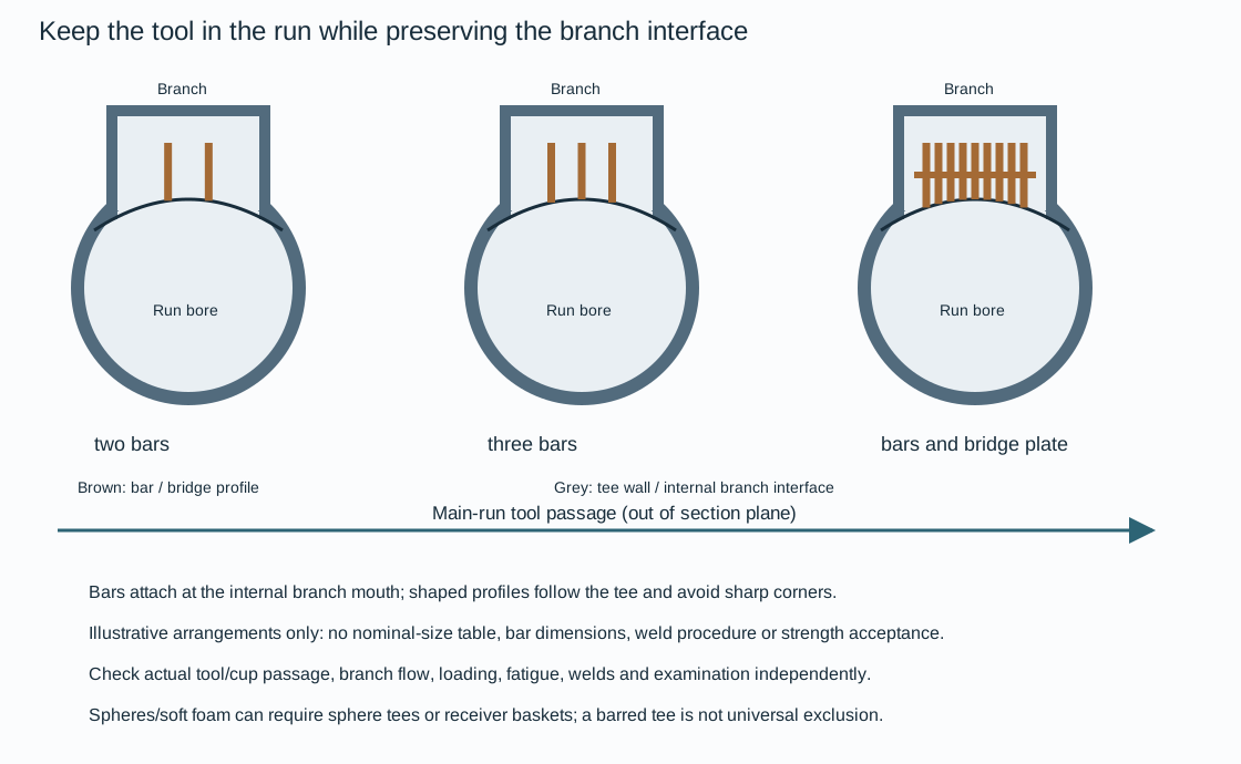
*Figure 12.4. Qualitative two-bar, three-bar and larger bar/bridge-plate arrangements at an internal branch mouth. The curved profile represents the run-side interface; tool passage is normal to the illustrated section. The patterns explain exclusion geometry and are not fabrication selections for any nominal size. No thickness, spacing, bar count rule, weld procedure or load capacity is specified by this figure.*
- Fit the profile to the tee curvature and installation angle, removing sharp corners that can catch or damage cups, discs or tool features.
The illustrated attachment basis includes a full-penetration weld detail, but the actual weld design, procedure and examination belong to the adopted material and fabrication requirements.
- Evaluate tool impact/loading, attachment strength and fatigue independently from clearance.
- Evaluate branch flow separately: a barrier that stops a tool can also alter flow area, collect debris or create a local restriction.
The suggested geometry is not a complete procurement specification.
The tool type can change the appropriate alternative. Spheres and soft foam pigs can stop, suffer damage or be lost at normal or barred tees. A selected sphere tee uses a perforated internal pipe to retain the sphere while allowing side-branch flow, with fabrication and possible corrosion/drainage consequences. A receiver catching basket can keep a sphere or foam tool out of the kicker line, but adds its own collection, retrieval and debris-removal duty. None of these alternatives establishes universal passage or exclusion from a drawing alone.
- Examine the actual selected tool and its cups/discs against the tee and adjoining bore, rather than optimize bar spacing in isolation.
Branch spacing that coincides with cup/disc separation can undermine the intended drive or let the tool stall.
- Retain the tool set, dimensions, material and attachment/examination basis in the selected design and installed record.
A later inspection tool or softer cleaning tool reopens the affected interface even when the pipe and nominal tee size are unchanged.
## Separate slug arrival, gas–liquid separation and liquid storage
A two-phase pipeline can deliver liquid steadily, displace accumulated liquid during a flow increase, or send it ahead of a pig in a short interval. Those modes differ in volume, rate, gas content and droplet behavior. The downstream slug catcher has to separate phases while accommodating the liquid imbalance and providing the required supply to its liquid-treatment system.
A vessel-type catcher can use a relatively compact footprint. Large required storage can make a multiple-pipe arrangement attractive. A multiple-pipe catcher uses primary bottles for separation and storage, with secondary bottles serving storage. Its countercurrent displacement of gas and liquid can promote carryover if the geometry and arrival rate are unsuitable. A parking-loop arrangement separates the compact separator from a long storage loop and can save platform space by locating storage elsewhere. It relies more strongly on its selected controls and operating sequence.
These are alternatives with different plot, manufacture and operation consequences, not three equivalent ways to provide nominal volume.
In the multiple-pipe arrangement, flow splits from an inlet manifold through downcomers into primary bottles. Reduced velocity and appropriate downward inclination encourage stratification. Droplet settling needs residence length before gas rises toward the outlet. Bends and impingement can also deposit droplets, while tee orientation affects phase separation. The relative importance of these mechanisms changes with gas velocity and droplet size.
A geometry suitable for slow pig arrival can be inadequate for mist-bearing steady flow.
One multiple-pipe hydraulic approach assigns high-flow separation to the horizontal primary-bottle section before the gas risers. An older approach placed more of that demand on very large risers. These approaches have different length and riser-size consequences and should not be averaged into one dimension rule.
- Retain the selected separation model, required performance and physical fluid properties when choosing bottle count and geometry.
### Keep separation and storage paths identifiable
Separation and storage paths must remain distinct when nominal vessel/pipe volume is converted into usable inventory.

*Figure 12.5. Authored functional alternatives for a vessel separator with separate surge drums, a multiple-pipe arrangement with primary and secondary bottles, and a separate-separator/parking-loop storage concept. The vessel view keeps liquid transfer and displaced-gas return distinct. The multiple-pipe plan identifies the primary entrance separation region, downstream storage, gas-riser path and lower liquid collection header; secondary bottles have a storage-only function. No pressure equalizer header is included. The parking-loop view is a physical concept, omitting compressor, control and operating-valve networks. No source dimensions, separation efficiency or storage capacity are adopted. [Structured functions, conditions and geometry relationships](assets/C11/c11-slug-topology.json) and the [native drawing implementation](assets/C11/c11-slug-topology.draw.py) preserve the representation.*
In the depicted vessel alternative, an elevated phase separator sends liquid through a lower connection to surge storage, while a separate gas-return connection communicates with the separator gas region. The stored liquid leaves through its own lower outlet. The elevation and the two connections affect liquid transfer and displacement. They cannot be reduced to an unexplained line joining two vessels. Actual pressure duty, transfer resistance, level relationships and gas-return capacity remain design inputs.
A compact separator footprint can be useful where plot space is limited, while remote surge storage changes the interface and support requirements.
In the multiple-pipe alternative, the inlet splitter and header feed downcomers into **primary** bottles. Their entrance sections before the first gas riser provide the selected high-flow separation region. The remaining primary lengths provide storage, and **secondary** bottles provide storage only. Gas from the primary separation region reaches the riser/header outlet path. Liquid reaches the low liquid header.
The lower-end connection makes storage exchange possible, but the adopted heavily loaded primary-bottle evaluation still assumes **no lower-end liquid transfer to other bottles**.
- Do not credit secondary storage as an automatic escape path when checking a fast incoming slug.
An equalizer joining bottle gas spaces is a different connection from the intended gas outlet. A historical arrangement contains such a header, but its geometry-sensitive gas transfer carried liquid from primary into secondary bottles in the reported model assessment. The adopted multiple-pipe method excludes the equalizer system. The authored topology preserves the selected method by omitting it. Adding that connection back because it appears in an old full-system drawing would change the hydraulic basis.
A parking-loop concept separates the phase separator from a long storage pipe. A sphere separates entering parked liquid from gas already in the loop, with a selected displaced-gas path at the far end. That physical arrangement can reduce the countercurrent gas/liquid interaction characteristic of multiple-pipe storage and can separate platform space from storage location. Its dependency on a strict adopted operating procedure remains consequential. A source schematic showing only the valves used for receiving liquid is not a complete operational design.
The functional sketch gives neither an executable receiving/discharging lineup nor a compressor or control arrangement.
An arrangement capable of partial isolation also changes the duty. A particular multiple-pipe example permits continued normal production on its remaining section, but prohibits sphering while partly isolated.
- Do not equate that state with normal full catcher capacity or ordinary pig-arrival capability.
- Define which parts, gas paths and liquid storage remain available for the actual evaluation.
The inventory and usable-volume methods below supply separate quantitative checks. The topology alone supplies neither.
### Calculate intercepting volume separately from downstream buffer
For the adopted inventory method,
\[
V_{sc}=V_{int}+V_{buffer}.
\]
In this equation, all volumes are in m³. \(V_{sc}\) is required usable liquid capacity. \(V_{int}\) is the intercepting volume for the largest assessed arrival imbalance. \(V_{buffer}\) is the liquid buffer required by the downstream treatment/operating philosophy. Neither quantity is the total metal-envelope volume of every bottle.
The intercepting volume depends on the maximum difference between arriving liquid and the amount the downstream process can remove over the event. For an arrival/removal time balance, define \(V_e\) as added liquid above the selected initial buffer condition, and use
\[
\frac{dV_e}{dt}=Q_{in}-Q_{out},
\]
In this balance, both flows are in m³/min and time is in min.
- Determine the largest accumulated positive inventory over the assessed event, including the real initial state and the outflow that remains available.
A delayed or tripped downstream system changes that volume even if the pipeline sends the same slug.
Evaluate retained and interrupted downstream removal separately; the same pipeline arrival can require different intercepting volume.

*Figure 12.6. Authored time balances for the hypothetical 10-minute arrival. The solid curve retains the assumed removal flow; the dashed curve loses removal during arrival. The six-cubic-meter downstream buffer is a separate initial allocation. The graph specifies no bottle geometry or actual process capacity; [structured method data](assets/C11/c11-methods.json) retains the assumptions and results.*
Regular pigging can use the accumulated liquid between selected intervals, while occasional pigging may encounter the largest holdup at the permitted low-flow condition. Terrain slugs and restart from standstill can require transient prediction rather than subtraction of two steady holdups. Bypass pigs can spread liquid arrival over a longer period in suitable applications, trading pigging/operation complexity against catcher demand. They do not automatically reduce total produced liquid or establish the required downstream buffer.
## Make the capacity useful through separation and drainage geometry
- Choose primary-bottle number and diameter first for the required separation duty, then develop storage and any secondary bottles within the plot.
For a project adopting one particular droplet-separation method, the entrance section before the gas riser is evaluated for separation better than 99%. Gas velocity in the bottle is no higher than 2 m/s to avoid excessive required length. Fluid properties, droplet distribution and residence behavior still determine that length. The velocity limit alone does not establish separation. For a project adopting this particular multiple-pipe method, evaluate the primary bottle under the worst-case assumption of no liquid flow from its lower end to other bottles.
- Do not credit secondary-bottle transfer when assessing that loading and choking condition.
The method also allows for maldistribution by assessing the most heavily loaded primary bottle at 20% above equal share. This allowance applies to the heavily loaded bottle, not 20% extra total fluid in every bottle simultaneously.
Slope affects both filling and gas escape. During an arrival, liquid must descend without choking the ascending displaced gas path. A steep slope can improve part of that behavior but create impractical structural height or inefficient storage. A dual-slope arrangement can separate the steeper separation/filling section from a shallower storage section. For a project adopting this particular dual-slope method, the general storage/secondary-bottle minimum is 1% and the recommended separation-section maximum is 2.5%.
A documented slower-flow arrangement used a 0.4% storage slope under its own conditions.
- Keep the choking/separation method and operating case with each choice.
That slower case does not establish a fast-arrival exception. Carry slope-induced fall into support height and plot geometry.
- Iterate storage length, primary/secondary count, bottle slope, gas riser location and maximum liquid level.
- Confirm volume again after actual dimensions and spacing are set.
The useful maximum fill is constrained by the gas-outlet geometry and carryover behavior, not only by the pipe's full circular volume. Keeping high-level/high-flow operation brief can be an operational requirement rather than an excuse to label every full bottle an adequate separator.
Liquid headers need drainage and cleaning access.
- Locate them to avoid gas carry-under and sludge accumulation.
Header diameter reductions described for a particular model study remain limited by blockage and cleaning considerations. Reducing diameter solely to save steel can remove the useful operating margin. Gas-outlet pressure drop can also make liquid levels differ between bottles. A selected symmetrical gas-outlet arrangement can address this distribution. An equalizer header originally intended to improve distribution is a separate proposal. Model work for one arrangement found that gas crossing from primary to secondary bottles carried liquid with it and impaired performance.
For a project adopting that multiple-pipe method, equalizer headers shall not be used.
- Balance the intended gas-outlet distribution without assuming that any additional connection between bottles is beneficial.
Level measurement must represent what is actually in the bottles. Water or glycol density can change differential-pressure indication and give different levels in neighboring bottles. Sludge can block taps and condensate can accumulate in a long gas impulse line. Appropriate tap locations, drainage and, where selected, multiple measurements or density-sensitive alternatives address different errors. The multiple-pipe practice excludes instrument bridles under its particular integrity basis.
That restriction is local. It does not reverse the useful bridle arrangements for vessels in [other services](#chapter-c13) or the broader sensing methods in [instrumentation](#chapter-c22).
### Preserve the lower liquid path at the inlet expansion
The inlet section includes the pipeline end, splitters, inlet header, entry restrictions, downcomers and expanders. It divides the entering mixture and begins phase organization before the primary separation length. Under the adopted multiple-pipe method, the pipeline diameter is maintained to the inlet to avoid unwanted acceleration. A tee splitter receives the stream perpendicular to its branching runs. Successive splits can divide the path into parallel streams.
The intended distribution needs the selected passage areas, backpressure and operating condition. The appearance of symmetry alone does not prove an equal liquid share.
Low-flow, liquid-rich arrivals such as a sphered slug can make entry geometry particularly important. The local restriction method describes porthole passages at most 40% of the **inlet-header inside diameter**. This is a diameter statement, not a 40% area opening, and is not a complete restriction-sizing calculation. The eccentric location near the lower downcomer wall guides the liquid and reduces the unsupported jetting that can generate mist or foam. It also avoids the upstream dirt pocket of a poorly located obstruction.
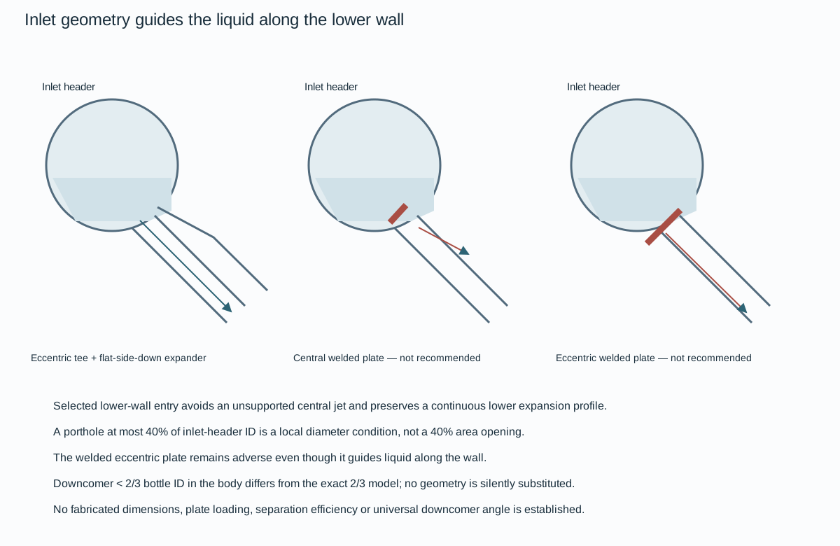
*Figure 12.7. Qualitative lower-side eccentric tee and flat-side-down expander under the adopted construction method, alongside centrally and eccentrically located welded splitter plates. **Both welded-plate alternatives are not recommended in the depicted method.** Wall guidance in the eccentric plate does not reverse that disposition. The view supplies no plate loading, dimensions, fabricated specification or validated separation result.*
The selected construction uses an eccentric tee on the inlet manifold followed by an expander with its flat side down, replacing the internal welded constrictor approach. Downstream expansion promotes segregation while the lower path remains continuous. The related bottle-entry flat-side-down expander avoids a lower-slope discontinuity that can disturb developing stratified liquid flow. A flat-side-up example and flat-side-down examples are distinct geometries. They cannot be exchanged merely because their nominal end sizes agree.
The local method favors a downcomer inclined at approximately 45° to promote stratification, rather than treating every vertical downcomer as equivalent. It separately describes an existing downcomer diameter less than two-thirds of bottle diameter, while a later model uses an exact two-thirds geometry.
- Preserve the adopted model's assumptions and actual inside bores.
- Do not silently replace the inequality by the model value.
- Do not convert a model dimension into a universal fabrication rule.
Separation and storage slopes also remain distinct. The general dual-slope method recommends a 1% minimum for storage/secondary sections and a separation-section maximum near 2.5%. A particular slow-flow storage concept uses 0.4%. Another drawing shows a 3% separation section with a 1% storage section. The slow-flow operating qualification and the difference between the drawn 3% example and the general recommendation remain attached to those cases.
No single combined slope prescription is inferred.
- Determine the actual geometry with the selected separation, filling/choking and usable-volume evaluations, then account for support height and plot consequences.
### Distinguish the deposition mechanism experiment from the working panels
Gravity, turbulent diffusion and impingement in an entry bend can contribute differently as droplet size changes. The mechanism comparison below comes from a configured numerical experiment, not the six-panel design lookup. It uses gas velocity 3 m/s, a 45° downcomer and a printed diameter ratio of 0.75. The surrounding dimensions are a 1.22-m bottle and 0.9-m downcomer. Its assumed maximum droplet size is described as 500 μm, while the plotted size axis reaches 600 μm.
- Preserve the stated assumption and displayed axis separately rather than silently replace either with the later 750/1000-μm working-panel cases.
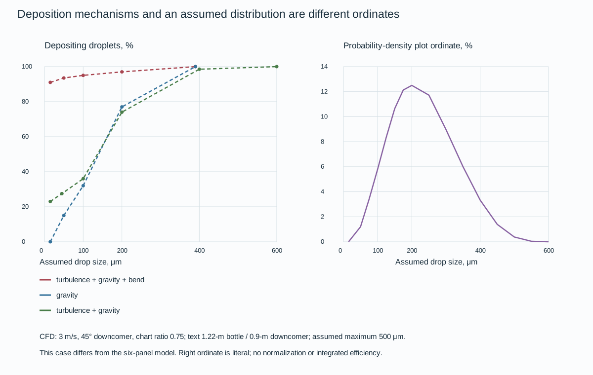
*Figure 12.8. Original graphical recovery of the configured deposition comparison: gravity; turbulence plus gravity; and turbulence, gravity and bend. The assumed droplet-distribution shape uses its own right-axis ordinate in the original and is separated into a second native panel to keep the quantities distinct. The recovered deposition allowance is estimated ±2 percentage points; the distribution-ordinate allowance is estimated ±0.5 percentage point. These are author reading estimates, not simulation accuracy bounds.*
At an assumed size near 100 μm, the graphical gravity result is about 32% depositing, turbulence plus gravity about 36%, and the combined bend result about 95%. Near 200 μm, the gravity and turbulence/gravity readings are about 77% and 74%, while the combined bend curve is about 97%. These local readings show the strong configured influence of the entry bend without claiming that turbulence always improves every point. Larger droplets increasingly respond to gravity. Smaller droplets can deposit by following turbulent fluctuations toward walls.
The mechanism depends on the actual flow and entry geometry.
The experiment does not supply all fluid-property/temperature inputs or validate scale-up. The plotted probability-density percentage lacks an established measure and normalization here; do not integrate or weight it to infer aggregate efficiency.
The [experiment data and conditions](assets/C11/c11-phase-experiments.json) keep the mechanism results distinct from the later model's gas/liquid densities, viscosity, 2/3 ratios and duty limit.
### A branch can take different shares of gas and liquid
A two-phase branch does not necessarily receive equal fractions of the two phases. Orientation, flow regime, superficial velocities and geometry affect which phase enters it. A downward arm can receive much of the liquid while gas continues through the main. An upward arm can take gas with little liquid until the selected flow condition changes.
- Use the following experiments to understand that separation mechanism, retaining their scale and conditions.
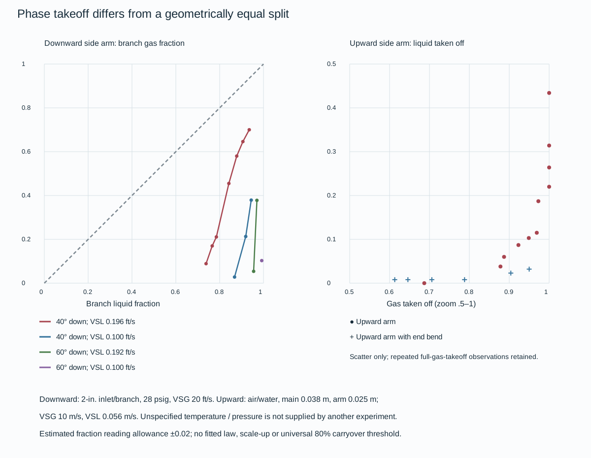
*Figure 12.9. Left: four original series for 40° and 60° downward arms, with 2-inch inlet/branch diameters, 28 psig pressure and superficial gas velocity 20 ft/s. The series retain their separate superficial liquid velocities of 0.196, 0.100, 0.192 and 0.100 ft/s. The diagonal is an equal-phase-fraction reference, not a fitted experimental line. Right: unfitted air/water observations for a vertical upward arm and an upward arm with a bend at the end of the main. These use main diameter 0.038 m, arm diameter 0.025 m, superficial gas velocity 10 m/s and liquid velocity 0.056 m/s. The right horizontal axis is zoomed to 0.5–1.0. Estimated reading allowance is ±0.02 in phase fractions; the single-marker and repeated-abscissa observations remain intact.*
For the 40° downward arm at liquid superficial velocity 0.196 ft/s, one recovered point near 0.84 of the entering liquid gives about 0.46 of the gas entering the branch. Equal geometric flow division would miss that phase difference. The other liquid-velocity and angle series are not an interpolation grid: the 60°/0.100-ft/s series contains only one plotted observation. Connecting the source's joined multi-point traces is useful for visual comparison within each series, but no new line fit, unobserved operating domain or experiment-scale conversion is supplied.
For the upward-arm air/water experiment, one point near 0.95 gas takeoff has approximately 0.10 liquid takeoff in the simple-arm series, while the end-bend series remains near 0.03 liquid takeoff at similar gas share. Several simple-arm points at full gas takeoff range from about 0.22 to 0.43 liquid takeoff. Collapsing them into one invented curve would erase the observations. Near-zero markers are retained as approximate readings rather than forced to exact zero. The experiment does not state the pressure and temperature needed to transplant its properties to another service.
The local account associates good upward separation with gas takeoff below roughly 80% and describes a selected 70/30 two-riser arrangement using that behavior. The observation and that implementation are not a universal carryover threshold or automatic design split. Larger-scale bottles, condensate properties, mist size and actual riser restrictions need the applicable evaluation.
- Compare the operating state and geometry, including partial availability, before making the phase-split evidence a design input.
### Symmetry belongs to the gas-outlet pressure path
Gas leaving the primary bottles passes through risers and a collection header to the outlet. An undersized or unbalanced outlet path can impose different gas pressures on bottles. Liquid levels can then shift by manometer action, with bottles nearer the outlet rising relative to the others. A layout that balances this path addresses a different mechanism from adding a gas equalizer between storage bottles.
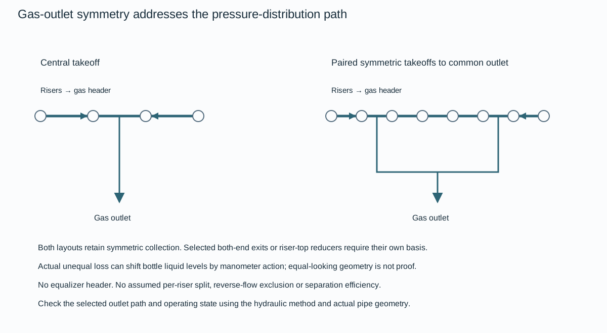
*Figure 12.10. Two qualitative collection configurations: a symmetric central header takeoff and paired symmetric takeoffs collected into a common central outlet. Circles represent riser connections. The arrows show intended collection directions; they do not establish measured or calculated flow shares. No equalizer header is added.*
The adopted gas-outlet method also considers gas exiting both ends of a header or selected reducers at riser tops to balance distribution. These arrangements require their actual pipe, resistance and operating basis. A two-riser approach can depend on a deliberately sized gas split and a separately evaluated carryover condition. The symmetric drawing does not create that split, exclude reverse flow or justify adding arbitrary extra risers.
- Preserve the intended primary-bottle gas escape and liquid collection paths, then verify pressure distribution and the heavily loaded arrival state under the hydraulic method.
The liquid header has a separate elevation duty. Under the adopted drainage method, locate it below the bottles' lower ends to avoid gas carry-under during liquid removal.
- Keep low-point drains, distributed liquid outlets and accessible header ends for sludge removal and cleaning.
A diameter reduction shown workable for one model remains bounded by dirt blockage and cleaning access. Outlet geometry cannot establish either useful storage volume or gas/liquid separation efficiency without the corresponding calculations and operating-state checks.
### Read choking onset as a configured case, not a slope law
During rapid liquid receipt, descending liquid must leave a path for displaced gas. At a configured intake rate, stratified flow can no longer be maintained and the bottle becomes choked with liquid. Bottle slope affects that onset, but also the height and storage geometry. A steeper bottle is therefore not automatically a higher-capacity or better-separating choice.
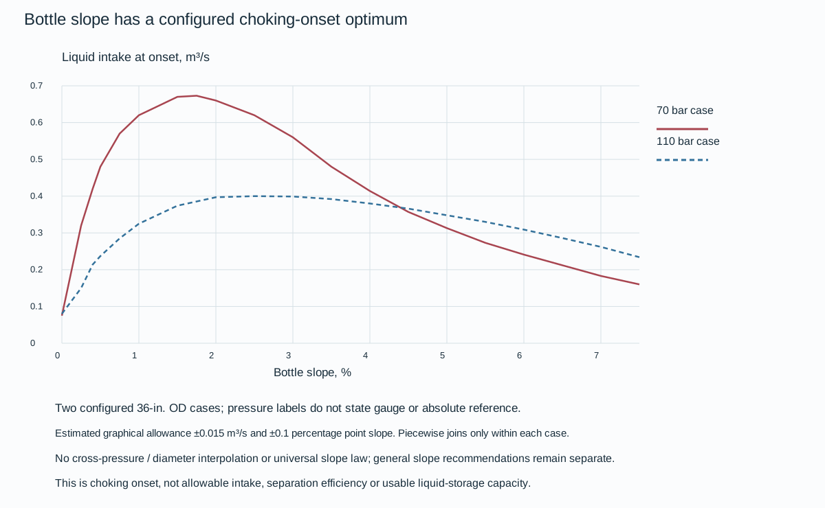
*Figure 12.11. Approximate original-curve recovery for two configured **36-inch outside-diameter** bottle cases labeled 70 and 110 bar. The pressure labels do not state gauge or absolute reference. The plotted intake rate is choking onset in m³/s, with bottle slope in percent. Estimated graphical reading allowances are ±0.015 m³/s and ±0.1 percentage point of slope. [Saved case data and model limits](assets/C11/c11-choking-curves.json) preserve the configurations; no cross-pressure or diameter scaling is supplied.*
In the 70-bar configured case, the recovered intake at a slope near 1.5% is about 0.67 m³/s and the plotted peak is near 1.7–1.8%. At 3% the curve falls to about 0.56 m³/s, and at 5% to about 0.31 m³/s. The 110-bar case peaks more broadly near 2.5% at about 0.40 m³/s. Its 0.4% marked operating slope gives about 0.21 m³/s. These comparisons establish the chart's configured trend, including the descending side of each curve, rather than a universal monotonic benefit from slope.
The underlying account describes a Kelvin–Helmholtz-based model supported by simulation experiments and reports a 70-bar case prediction near 0.67 m³/s compared with approximately 0.70 m³/s measured in practice.
- Keep predicted and reported measured quantities distinct.
The complete fluid properties, geometry and solver inputs for generating another case are not supplied by these two traces. No pressure-reference correction, pressure interpolation or diameter-independent law is invented from their difference. The 36-inch OD label is not the inside diameter for a volume or stress calculation.
Straight joining between saved slope samples can compare positions within the same configured case. It does not create an allowable operating intake, a separation-efficiency result or usable liquid capacity. The chart's domain up to 7.5% also does not replace the separate general minimum-storage and recommended maximum-separation slopes in the adopted geometric method.
- Resolve the applicable arrival state, no-transfer/maldistribution loading, fluid/geometry basis and operating limits before choosing a bottle slope.
Then carry the actual fall and buried or supported configuration into storage, stress and construction evaluation.
### Calculate usable storage from the liquid surface and riser geometry
The liquid imbalance calculated above must fit within usable bottle geometry. Under the multiple-pipe method developed here, maximum primary-bottle liquid level is at the intersection of the lowest gas-riser centerline with the lower inner wall of the bottle. The sloping upstream region is partly filled at that horizontal liquid level. Crediting its entire circular cylinder volume would count space that must remain available for gas communication.
For the method's depicted single- or dual-slope geometry, the partly filled contribution is
\[
V_{part}=\frac{\pi D_b^3}{8\tan\theta},
\]
In this equation, \(D_b\) is bottle internal diameter in m. \(\theta\) is the angle of the bottle beneath the riser to horizontal, and \(V_{part}\) is in m³. For its dual-slope construction the riser reference is \(D_b/\tan\theta_2\) from the slope intersection, where \(\theta_2\) is the steeper section's angle. These expressions describe the supplied geometry, not every arbitrary bottle profile or an additional process buffer.
Use the slope actually beneath the riser for volume. Calculate fully filled portions and other bottles separately, then compare total useful inventory with the arrival/removal/buffer case. The separate dual-slope riser-distance convention does not transfer a volume from one slope to another.
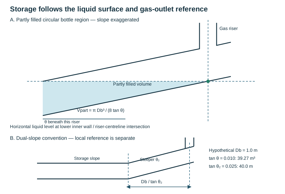
*Figure 12.12. Authored schematic of the partly filled primary-bottle region. Slope is exaggerated, the liquid level is horizontal, and its reference reaches the lower inner wall at the gas-riser centerline. A separate dual-slope panel marks the local riser-distance convention. [Structured geometry and calculations](assets/C11/c11-slug-separation.json) distinguish the partly filled volume from total catcher inventory. Secondary-bottle free surfaces must retain their own gas path; this sketch is not a fabricated section.*
Secondary storage must be arranged so that its full-condition free surface is not wholly within its riser. Different slopes and lengths can change that position. A nominal storage volume that fills the wrong gas-outlet region can lose the phase-separation function just when the arrival demands it.
### Check the gas escape path in its heavily loaded pigging state
Under the adopted riser method, define the load factor
\[
\lambda=\sqrt{\frac{\rho_G}{\rho_L-\rho_G}}\,v_{SG},\qquad
v_{SG}=\frac{(1.2/n_{pb})Q_{pipeline}}{m\pi D_r^2/4}.
\]
In these equations, gas and liquid densities \(\rho_G,\rho_L\) use kg/m³. \(D_r\) is riser internal diameter in m. \(m\) is risers per primary bottle, and \(n_{pb}\) is primary-bottle count. \(v_{SG}\) and \(\lambda\) are in m/s. \(Q_{pipeline}\) is the method's pipeline gas-flow quantity in m³/s on the actual condition basis corresponding to the highest pigging/sphering velocity, rather than an unconverted standard flow or an assumed maximum normal throughput.
Its check uses \(\lambda\leq0.20\) m/s to settle droplets larger than 2 mm in the gas riser.
- Apply it to the bottle receiving 1.2 times equal share during pig/sphere arrival, with **no liquid transfer from that bottle to other bottles**.
Crediting transfer reduces the gas-escape demand and changes the prescribed case. This coarse-drop riser check does not establish the primary section's much finer mist separation.
Under this method the riser height is at least the lesser of five riser diameters and 5 m:
\(h_{riser}\geq\min(5D_r,5\,\mathrm{m})\).
Two risers can introduce gas-flow imbalance: the arrangement discussed by the method throttles the second to about 20–30% of total gas under its own conditions. A maintenance state with part of the catcher isolated cannot inherit full-unit pigging capacity. Its no-sphering restriction remains consequential.
### Check the droplet regime before turning settling time into length
A uniform-droplet calculation explains the dependence on size, density and viscosity. It is a limited model. The developed separation method instead prefers a droplet-size distribution with turbulent deposition, inlet expansion and the gas-riser junction represented. For a small droplet in the supplied Stokes regime,
\[
V_s=\frac{(\rho_L-\rho_G)gd_d^2}{18\eta_G},\qquad
Re=\frac{V_s\rho_Gd_d}{\eta_G}<1.
\]
In these expressions, \(d_d\) is droplet diameter in m, and \(\eta_G\) is gas dynamic viscosity in Pa·s. \(g\) is in m/s², and \(V_s\) is in m/s. The density definitions above remain.
- Compute the velocity, then verify its regime.
The supplied swarm relationship is \(V_{s,swarm}=V_s(1-H)^n\), followed by \(t_s=D_b/V_{s,swarm}\). \(H\) is dimensionless liquid holdup fraction. The method gives \(n\) ranging from 4.65 to 2.39 over \(0.1\leq Re\leq500\), without a complete interpolation law. A droplet distribution with turbulence/wall deposition cannot be replaced by one uniform small size or an unjustified exponent selection.
At higher Reynolds numbers the drag relation and velocity must be solved on their applicable basis. The available large-Re expression in this treatment lacks a dimensionally valid velocity basis. Dimensional analysis identifies the deficiency but does not qualify a replacement drag law. No high-Re velocity prediction is made from it here. This limitation does not invalidate the low-Re method or justify skipping the developed deposition-model path.
For the developed deposition path, match density, maximum droplet size, inlet/bottle geometry and no-re-entrainment conditions to the [complete working-panel basis below](#c11-slug-deposition-lookup) before reading $L/D_b$.
A representative coarse read at 60 kg/m³ gas density, 1000 µm maximum drop size, 2.0 m/s bottle gas velocity and the 99.5% curve is about \(L/D_b=10\).
- Carry an illustrative reading band of 8–12 for this graphical observation, rather than treat it as precise tabulated data.
The [structured separation method](assets/C11/c11-slug-separation.json) preserves model conditions, quantities and uncertainty. The 40/60/80-density graphs do not consistently support monotonic higher-density substitution.
- Preserve that limitation when the actual density is not represented.
- Establish the applicable model or graph disposition instead of choosing a supposedly stricter curve.
If the required length will not fit, revise primary-bottle count or diameter and repeat the flow/geometry evaluation.
### Use the separation chart only with its complete model gates
The developed deposition model provides six working panels rather than one general length curve.
- Select the represented gas density, maximum droplet size and target efficiency together, after confirming the inlet and bottle geometry.
A line labeled 99.5% describes the model's predicted separation at its conditions. It is not a measured efficiency certificate for an installed catcher.
The common model basis is liquid density 600 kg/m³, liquid-to-gas volume ratio 0.05 and gas dynamic viscosity approximately 0.000012 Pa·s. Gas density is 40, 60 or 80 kg/m³. The panels separately use maximum droplet sizes 750 and 1000 μm in a Kataoka-labeled distribution. The geometry is a 45° downcomer followed by a 1.5D bend and flat-side-down expander. Both downcomer/primary-bottle and gas-riser/primary-bottle **inside-diameter ratios are 2/3**.
The model assumes that liquid, once deposited, does **not re-entrain**. All these gates travel with the chart. Selecting density alone does not establish compatibility.

Figure 12.13. Approximate original-curve recovery for six panels, with efficiency families 80%, 90%, 93%, 96%, 99% and 99.5%. The recovered velocity spans and the top clipping at $L/D=30$ remain explicit. Shading above 2 m/s identifies plotted comparison space outside the stated separation-section duty limit; the plot's 4-m/s axis does not authorize that duty. The lower-efficiency curves permit comparison but do not satisfy the selected method's requirement for **better than 99%**. [Recovered panel data and all model gates](assets/C11/c11-separation-curves.json) and the [native drawing implementation](assets/C11/c11-quantitative-curves.draw.py) preserve the curves without a fitted external equation.
For a represented panel and efficiency, read gas velocity on the horizontal axis and $L/D$ on the selected curve. Between saved samples, a straight joining of $L/D$ against velocity supplies an approximate graphical lookup.
- Do not interpolate between efficiency families, densities or maximum droplet cases, and do not extend a curve beyond its saved span.
The author-estimated reading allowance is the greater of ±0.5 in $L/D$ or ±5%, with ±0.03 m/s on velocity. This is graphical resolution, not an efficiency confidence interval or a design margin. A steep upper curve can make velocity uncertainty consequential, particularly near the clipped top of the chart.
Once the model basis is adopted and matched, convert the ratio using the actual primary-bottle inside diameter:
$$
L_{sep}=\left(\frac{L}{D_b}\right)D_b.
$$
In this equation, $D_b$ and $L_{sep}$ are in meters, and $L/D_b$ is dimensionless. The separation length runs from the model's bottle-entry reference to the first exit riser. It is distinct from the full storage length.
- Do not insert a 36-inch outside diameter or a nominal pipe label as though it were the inside diameter.
The [bounded lookup implementation](assets/C11/c11-quantitative-methods.py) reproduces the saved-data interpolation and teaching length conversion. Its duty mode rejects velocity above 2 m/s and efficiency at or below 99%. Its comparison mode does not turn those plotted values into permissions.
Droplet-size selection materially affects length: at 60 kg/m³, 1.5 m/s and 99.5%, the recovered 1000-μm panel gives approximately $L/D=6.25$, versus 8.87 for 750 μm. These are model readings, not project lengths or actual efficiency evidence. At 1000 μm and 1.5 m/s the 40-, 60- and 80-kg/m³ panels give approximately 8.92, 6.25 and 12.49. Their nonmonotonic order conflicts with the procedure’s suggested higher-density substitution; preserve that conflict.
No off-density selection, interpolation or presumed conservative curve is supplied here.
The 1000-μm choice reflects the stated empirical droplet basis for the adopted configuration. The smaller 750-μm assumption was suggested for vertical or strongly disturbing entries where re-entrainment could occur. Choosing that panel does not prove that a geometry violating the 45°/bend/expansion/no-re-entrainment model has become valid.
- Establish the applicable model or specific disposition before applying it to a different inlet.
If the required length cannot fit the plot, reconsider bottle count, diameter and flow, then repeat the actual model comparison rather than crop the separation section to the available space.
### Burial moves the transition, support and inspection questions
A sloping catcher body can lie below naturally sloping ground, inside a constructed mound on a level plot, or transition into an outlet access pit. These choices preserve different exposed lengths, support conditions and work spaces.
- Coordinate bottle gradient and liquid-header elevation with the ground model before choosing an earth profile.
Hiding a long pipe beneath fill does not remove its thermal movement, testing weight or differential settlement.
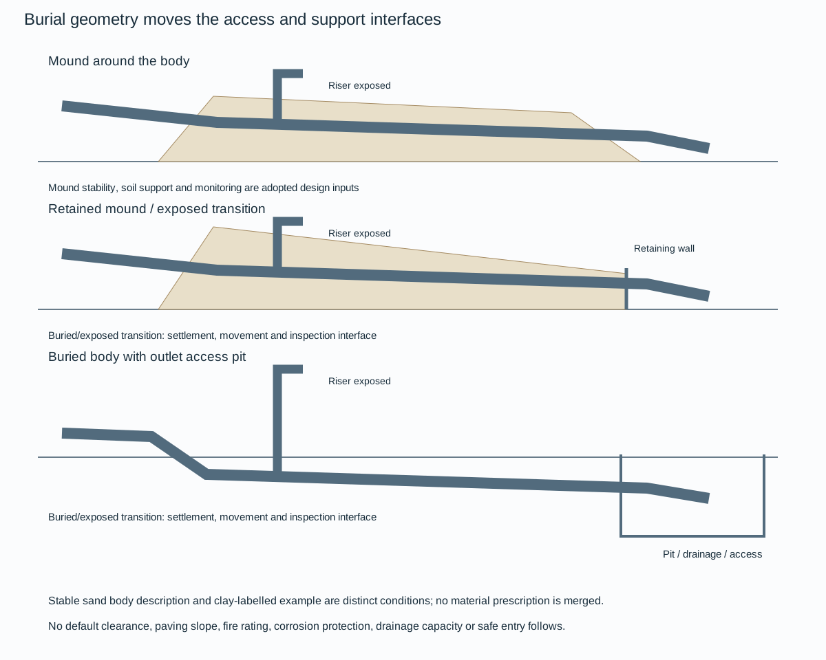
*Figure 12.14. Qualitative whole-mound, retained-mound/exposed-transition and buried-body/access-pit alternatives. The original-grade reference, exposed riser and buried/exposed pipe transition are kept visible. Dimensions, paving slopes and transit details are not transferred as universal clearances, fire protection or settlement allowances. This is an interface comparison, not a foundation or safe-entry design.*
The body description uses a stable sand mound, while a drawn mound example is labeled clay. Those are different source examples rather than a combined material prescription.
- Select mound stability, foundation preparation, drainage and pipe support for the actual ground and load basis.
A retaining wall or pit can reduce mound height while concentrating an exposed/buried transition at a wall penetration. The illustrated rubber transit detail is an example requiring its adopted movement and sealing basis. It does not qualify a generic settlement accommodation or fire barrier.
- Evaluate pressure, thermal expansion, slug or surge passage, support reactions, environmental loads and test contents in the actual supported or buried state.
Differential settlement of the catcher and adjoining structures can deform the exposed/buried transition even when each foundation appears locally adequate. The wall or pit must leave the pipe's intended load and movement path rather than impose an accidental restraint. [Stress evaluation](#chapter-c09) and [support/restraint design](#chapter-c10) provide the coupled mechanical account.
- Plan condition monitoring for the buried sections during design so routine assessment need not depend on unplanned excavation.
Header-end access remains useful for inspection and sludge removal. Ensure its removal and working space remains available beyond the mound or within the selected pit. Drainage, contaminant collection and access for maintenance belong to the real arrangement. A drawn pit provides no safe-entry condition or drainage capacity, and burial alone does not demonstrate the fire-resistance or escalation outcome claimed for a particular site.
- Evaluate those functions under the adopted hazard, corrosion and intervention basis before relying on the earth cover.
## Establish the installed pipeline through construction and precommissioning
Construction changes the configuration before the line begins its intended service. Stringing, bending, welding, lowering into the trench and backfilling create temporary support and deformation states. Onshore working strips need room for the construction spread and reinstatement of topsoil, drainage and other preserved features. Swamp flotation or push-pull installation offers different equipment and environmental consequences. Offshore S-lay, J-lay, reeling or tow methods create other curvature, tension, contact and vessel-motion histories.
- Select and analyze the actual method rather than represent all construction by an empty version of the operating model.
- Prevent debris and muddy water entering open pipe, control welding/examination in the actual field conditions and restore field-joint coating.
Before acceptance, establish the installed bore condition as well as the pressure boundary. A gauge-plate or caliper pig can identify dents/buckles that a pressure test is not intended to locate. Test and precommissioning tools also need a route and a receiver that can handle them.
For a project specifically adopting one pipeline hydrotest procedure, strength testing is followed by a leak-tightness assessment of portions that cannot be inspected for leaks during the strength test. The two phases use different pressure/temperature control logic. That procedure uses a strength basis of at least 90% specified minimum yield stress at minimum wall thickness. Its subsequent leak phase starts at 80% of strength-test pressure and permits temperature-driven fluctuation without adding or removing water. A separately conditioned combined test is another option. These are scoped pipeline test criteria, not numbers to impose on plant piping or special materials.
[System testing](#chapter-c18) develops boundaries, stored energy and restoration.
- Retain the applicable pipeline procedure rather than choose a larger number from another basis.
Route elevation makes test pressure vary along the line, and stronger/thicker sections may need a separately established test before incorporation. Temperature changes must be understood when interpreting pressure change.
- Treat tie-in welds that are outside the hydrotest boundary by the required additional examination.
After water testing, cleaning, dewatering, drying or inerting follow the service and precommissioning basis. Passing the pressure test does not establish a dry gas or a clean oxygen condition.
Records retain the actual installation: route/burial survey, pipe joint/tally identity, material/wall/coating, jointing/examination and test evidence, changes and their reasons, nonconformances and repairs. Handover also preserves operating limits, special states, pigging purpose and adjustment criteria, route/corrosion/valve monitoring, access and contingency arrangements. [Technical records](#chapter-c21) explains continuity. The pipeline's installed location and geometry must remain linked to those decisions.
## Make offshore facility piping maintainable in its actual space
Offshore facility piping and the transmission/riser interface have related but distinct duties. Congestion, restricted crane/support access, harsh external corrosion and costly intervention strengthen the case for deliberate layout and onshore fabrication. They also make a completely prefabricated fit without adjustment difficult.
- Preserve an appropriate field-fit allowance and verification of the actual structure/equipment interfaces, rather than force a spool into an assumed geometry.
Routing overhead, in central racks or beneath decks can preserve equipment access, while deck-level lines can obstruct operation and removal. The chosen position must still allow inspection, lifting and corrosion maintenance.
- Minimize unnecessary hydrocarbon connections over water.
- Retain removable sections where equipment servicing or modification actually requires them.
A facility maintenance spool and a seabed transmission tie-in need different joint strategies. A plant practice using periodic flanged removal points and a pipeline practice preferring welded tie-ins need not become one universal connection rule.
Wellhead flowlines can carry sand and have concentrated erosion locations. A selected target-tee or replaceable spool arrangement addresses access to an expected wear location, rather than making the whole line immune to erosion. Small connections susceptible to vibration or mechanical damage need their specified joining/bracing treatment. Closed vessel/instrument drainage retains hydrocarbon vapor, while deck-floor drainage needs the appropriate traps, slope, cleanouts and penetration arrangements. [Connections](#chapter-c07) and [drain architecture](#chapter-c12) carry the associated functions.
Corrosion at a support can arise from a wet crevice even with a suitable coating elsewhere. Support details must provide the required mechanical restraint and avoid moisture traps against the pipe, while permitting the selected removal/maintenance. Clearances between parallel surfaces and around penetrations need enough room for surface preparation and recoating. The detailed dimensions and material compatibility belong to the adopted arrangement. Rubber or another contact material is not automatically a suitable vibration, restraint and corrosion solution for every line.
## Design the rigid metallic riser across its interfaces
The riser account here concerns rigid metallic piping, its clamps and the associated expansion/tie-in arrangement. Flexible and nonmetallic risers require separate design bases.
- Define the topside, jacket and pipeline/spool interfaces with their loads, movements and responsibilities.
A code break does not terminate mechanical influence: the structure can move a support, and the pipeline can expand into the riser even where component scope changes.
The topside interface includes piping layout, terminal/valve and pigging access, electrical isolation, supporting structure and overlap of analyses. The jacket interface supplies actual members, dimensions, deflection, support types, protection and installation provisions. The pipeline/spool interface supplies approach geometry, expansion, tie-in method and an analysis overlap that can carry the interaction continuously.
- Avoid a disconnected pair of models in which each assumes the other boundary is fixed.
Weight includes steel, contents, coatings, attachments, anodes, marine growth and buoyancy. Water absorption by weight coating can change it. Pressure and temperature create both direct demands and movement under restraint. Residual lay tension, curvature and seabed undulations can remain after installation. Pigging/slugging, surge, waves/currents, wind and relevant seismic/ice conditions add other demands.
A modeled force list is not yet an evaluated combination: environmental direction, phase and the system configuration can make different locations govern under different cases.
Hydrodynamic evaluation must match water depth, wave/current theory and profiles, appropriate drag/lift/inertia coefficients and combined directions/phases. Shielding or amplification near jacket members changes the local flow.
- Distinguish the environmental descriptors required by the adopted analysis.
A maximum-wave condition is not replaced casually by a significant-wave height. Vortex excitation and fatigue are different checks from static yielding. [Mechanical analysis](#chapter-c09) supplies their broader interpretation, with the actual riser environment retained as input.
## Establish the support and installation state before evaluating it
A guide clamp controls transverse motion while retaining the intended axial movement/rotation. A deadweight clamp carries the selected weight path, with its downward axial restraint and other freedoms determined by its detail. An anchor restrains movement and rotation in the specified directions. Those functions cannot be assigned interchangeably because all three are called clamps.
- Select them from the required riser movement and reactions and carry the loads into the supporting structure.
Installation, hydrotest and operation create distinct states. Handling, load-out, transport, upending or retrofit can change gravity direction, support contact, temporary restraint and vessel-motion loading. Hydrotesting adds contents and pressure under its actual support/environmental condition. Operation adds thermal, residual and cyclic/environmental combinations. A temporary knee brace can reduce installation stress yet increase operational restraint.
Under the scoped installation arrangement it is removed completely after installation. The model and records must reflect that restoration.
Retrofit clamp alignment depends on as-built accuracy, diver measurements, fabrication/handling change, closure and adjustment tolerances. Provision for adjustment can avoid pulling the installed riser into an assumed location and creating unintended stress.
- Examine access for bolt tensioning and a design that limits stress concentrations under cyclic load.
The support's own weight and environment join the reactions transmitted by the riser. [Support function](#chapter-c10) explains the general distinction. The riser-specific state and adjustment must be established here.
Pipeline expansion can be restrained away from the platform or absorbed through a flexible geometry. Rock placement, trench/backfill, added submerged weight or an anchor change resistance. A spool/loop or selected flexibility changes the displacement accommodation. Lower seabed friction can increase movement reaching the riser, whereas greater friction can increase a pull-in demand. The “conservative” coefficient therefore depends on the question.
Settlement into another soil layer or scour can change resistance over time.
- Preserve the range and assumptions rather than assign one friction value to every state.
- Protect above-water, splash-zone and submerged supports according to their actual exposure and electrical relation.
A clamp can shield cathodic protection or create a difficult inspection location.
- Avoid a splash-zone support where practicable under the riser basis, and evaluate unavoidable locations for corrosion and access.
Protection must preserve the intended movement as well as integrity. A liner that grips an intended guide can create a different restraint.
### Read the riser clamp through its contact and attachment
Similar clamp outlines can represent different installed freedoms. Figure 12.15 compares three riser-to-jacket load paths and a separate retrofit adjustment arrangement. The guide has a split hinged clamp connected to a jacket sleeve through a structural member. Its lined inside diameter permits axial travel without significant restraint while contact limits movement perpendicular to the riser. The lining, coating and closure setting must preserve that function.
Tightening it into a gripping clamp changes the modeled boundary.
The deadweight detail adds a sleeve welded to the riser and a projecting flange that bears on the support clamp. Downward weight enters the sleeve/flange, the bearing face and the jacket connection. This one-sided bearing is different from a connection preventing axial movement in both directions. Rotation and other axial freedom depend on the detailed arrangement, including whether the bearing lifts clear. A device called a deadweight clamp must not be assigned a full anchor merely because its flange is labeled an anchor flange.
The illustrated anchor instead transfers reaction through a doubler attached to the riser by circumferential welds, into the connecting member and jacket. Its intended function is restraint in all directions, including torque, under the selected riser basis. That intention requires actual connection stiffness and capacity. An integral anchor flange welded into the riser string is another construction route with its own fabrication and pressure-component basis. It is not an interchangeable external doubler.
Material, parent wall, attachment welds, examination and fatigue assessment remain local to the selected route.

*Figure 12.15. Three separate installed support functions and an erection-state adjustment schematic. Guide travel arrows describe intended operating freedoms; adjustment arrows describe alignment before the final connection/closure is established. No load rating, spacing or adjustment dimension is encoded. [Structured clamp and state constraints](assets/C11/c11-offshore-support-interfaces.json) retain the distinction.*
Retrofit adjustment accommodates errors in as-built geometry, diver measurements, clamp position, closure, fabrication and handling. The selected arrangement permits adjustment at the riser clamp and connecting stub, and relative angular alignment at the jacket attachment. These are installation provisions for a stress-free fit, not unlimited travel after assembly. The local procedure's 250-mm adjustment allowance belongs to that installation basis.
- Establish the available axes and tolerance stack for the actual clamp, then record the closed, tensioned and restored operational configuration.
A temporary knee brace that was necessary during installation may need complete removal to restore the analyzed freedom.
Bolt tensioning needs sufficient bolt length and physical access for its tooling. Pre-tension must follow the qualified joint design.
- Include hydrotest contents, support weight, environmental load and the riser's transmitted reactions in the support/structure assessment.
Cyclic loading makes local concentration and bolt stress changes consequential. The drawing's contact topology cannot supply the reaction, preload, fatigue resistance or jacket capacity.
For the selected lined-guide procedure, ribbed polychloroprene lining is vulcanized to the guide, and coating protection at the travel interface may include specified external metal sheeting.
- Preserve clearance and travel through the entire coating/liner stack.
Ribbing also addresses shielding of cathodic protection. Retrofit supports require the selected electrical-continuity route. Above-water, splash-zone and submerged locations have different coating, corrosion-allowance and cathodic-protection conditions.
- Avoid splash-zone supports where practicable under that basis, and retain inspection access where they are unavoidable.
### Choose a marine attachment with its moisture and removal interfaces
A marine support can hide deterioration at the same contact through which it carries the pipe. Figure 12.16 separates fixed attachment from removable contact rather than claiming either eliminates corrosion. In the fixed examples, seal-welded plates or a doubler and stand-off carry reactions to the structural member. The doubler detail seals its ends and explicitly avoids penetrating the flow-line wall. A saddle alternative has its own vent-hole sealing detail.
These features have distinct fabrication and inspection routes. A seal weld at one interface does not justify sealing or drilling another.

*Figure 12.16. Qualitative fixed doubler/stand-off and removable split-clamp alternatives. The fixed load path includes the parent wall and attachment weld; removable contact needs its own liner, fastener and release/load-support procedure. The drawing does not certify corrosion immunity or hardware capacity.*
The removable examples include a sleeved U-bolt with support pad and a split clamp on a stand-off. Their sleeves/liners change contact and can reduce abrasion or vibration, but retained moisture, damaged coating or an unsuitable fit can still cause local damage.
- Select their material and coating compatibility, inspectability and actual contact pressure.
In the split-clamp family, the illustrated neoprene insulation belongs only to its insulated variant. The bare and coated-pipe variants cannot inherit that liner by appearance. Its slots belong in the bottom clamp only. Coating, clamp thickness and fastener selection are part of the actual detail rather than dimensions inferred from this panel.
Fixed details reduce the need to release a pipe-to-support joint during routine work but retain welded pressure-wall interfaces. A removable arrangement can permit equipment servicing or pipe changeout while requiring a safe load path before fasteners are loosened. A pipe can remain supported in normal service and become unstable during partial removal.
- Plan temporary support, tool access, isolation and restoration under the applicable work procedure.
The drawing itself grants no permission to release a clamp or repair a live attachment. Historic plating, galvanizing or paint choices remain subject to the adopted material/service restrictions.
### A deck collar and the riser clearance serve separate purposes
Figure 12.17 shows a raised collar attached to a deck around a riser. The collar-to-deck joint and the free clearance to the riser are separate interfaces. The space around the riser provides access for surface preparation and recoating and must also remain compatible with movement. A collar is not attached to the riser in this example. It does not carry riser weight or establish a pressure, fire-rated or watertight seal.

*Figure 12.17. Conceptual penetration section. The raised collar is attached to the deck; clearance remains between collar and riser. Actual coating/tool access, movement, deck and collar construction are project inputs. The local source clearance, collar height and schedule are not encoded as universal dimensions.*
Access has to be usable after installation.
- Account for adjacent pipes, bracing, insulation and the reach of the selected preparation/coating tools.
The local 2.5-in clearance and 4-in collar rise are detail examples rather than general offshore minima. A visible gap is not proof of tool access, and filling it with a later seal changes both access and movement.
- Keep the deck penetration, riser support and any separately required barrier/sealing function distinct in the drawings and inspection record.
[Structured interface data](assets/C11/c11-offshore-support-interfaces.json) connect these construction, operating and maintenance states without assigning an unverified capacity.
### Give ovalization its defined denominator
Flattening under manufacture, external pressure or bending changes the riser section and can contribute to buckling or collapse. A reported percentage is useful only with its normalization. One rigid-riser method defines
\[
F_o=100\frac{D_{max}-D_{min}}{D_{max}+D_{min}},
\]
This expression uses maximum and minimum outside diameters in the same unit, with a local 2.5% limit. A percentage normalized by mean diameter is twice this quantity and cannot be compared directly with that limit.
The [riser method data](assets/C11/c11-riser-seal-methods.json) retains this convention. Meeting that shape criterion alone establishes neither external-collapse resistance, fatigue life nor suitability for a plastic pull-in state.
### A J-tube creates an installation path and an annular environment
A J-tube must pass the riser and its pull-head through the actual bends while carrying the pull-in contact loads. Larger radii, smaller bend angles and fewer bends can reduce friction and imposed bending. Under one adopted rigid-steel pull-in criterion, routing uses typical bend radii near 100 pipe diameters and excludes radii below 50. The J-tube internal diameter is at least twice the riser diameter. These are local screening/design criteria, not a substitute for a pull-head passage and strain/collapse assessment.
- Analyze the pull-in step by step from bellmouth entry to the final position.
- Include back-tension, elastoplastic bending, riser/cable contact friction, radial bend loads, potential bellmouth or J-tube jamming and the load before the winch stops.
The pull-head must transmit tension without damaging the riser and must fit through the bend. A scaled geometry check can expose a jamming configuration before a load calculation is trusted. The winch, cable, J-tube and supports must share one evaluated installation basis.
The installed annulus creates another service environment. A selected seal excludes seawater and retains inhibited water or another compatible medium. Its restraint on the riser, flushing behavior and ability to retain the medium need assessment as well as nominal sealing.
- Provide the required sample/maintenance route.
The bellmouth can have different installation and operational reactions, and protection of the J-tube exterior remains a marine corrosion problem. A successful pull-in is not proof that the annulus will remain noncorrosive or that its seal permits the required operating movement.
### Select the seal for pressure direction, movement and replacement
The J-tube annular seal separates its retained medium from the sea. Its differential pressure depends on both fluid columns and their pressure references, not solely on water depth. Under a hydrostatic seal method,
\[
P_s=(P_j+\rho_jgH_j)-\rho_sgH_s.
\]
In this equation, \(P_s\) is inside-minus-outside differential pressure at the seal. \(P_j\) is gauge pressure at the top of the J-tube fluid. \(\rho_j\) is its density, and \(\rho_s\) is seawater density, both in kg/m³. \(H_j\) is height from the seal to the top of the retained fluid. \(H_s\) is seal depth below **mean sea level**, both in m.
With \(g\) in m/s² the result is Pa. The simple balance assumes hydrostatic columns, consistent atmospheric gauge reference and stated densities. Wave effects, temperature/density variation and gas compressibility need their actual treatment.
Changing retained medium can reverse seal-demand direction and magnitude. Evaluate both actual fluid columns; a constant-density gas contrast is not a compressible-gas inventory model.
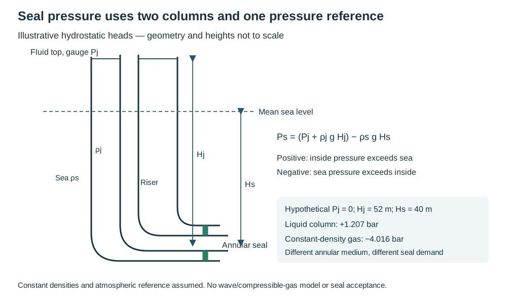
*Figure 12.18. Authored hydrostatic reference sketch. Top-fluid gauge pressure and its seal-to-level height are distinct from seal depth below mean sea level. The inside-minus-outside sign permits either pressure direction. [Structured seal data](assets/C11/c11-riser-seal-methods.json) supplies the hypothetical liquid/gas comparison and scope; geometry is illustrative.*
Seal construction also changes movement and repair. A conical elastomer seal relies on maintained contact/compression and limited motion. An inflated toroidal arrangement has a different shearing/slipping damage question. A boot installed for pull-in can suffer wear and may not be replaceable afterward. An integral diaphragm needs protection during pulling.
A zipped form can be installed later and replaced. A longer bellows sleeve can accommodate greater axial travel. An anchor-type seal keeps compression by preventing axial riser motion at the bellmouth, thereby transferring the thermal/restraint question into the system. These are functional alternatives, not interchangeable nominal seal ratings.
The described families include illustrative differential-pressure capabilities around 2 or 5 bar and millimeter-scale travel allowances. A family name does not qualify the actual calculated differential pressure.
- Establish the actual seal's permitted pressure direction, travel, attachment and retained compression, installation damage controls and replacement access.
- Combine those inputs with the riser's operating and shutdown movement/load assessment.
A sealed annulus that no longer permits its intended expansion has changed the mechanical system. A freely moving riser with an inaccessible worn seal has changed maintainability.
- Retain both consequences with the installed medium and sample/inspection plan.
## Preserve inspection, replacement and the actual installed route
Inspection-tool geometry can govern bends, bore changes, valves and flanges early. For a riser arrangement specifically adopting the following intelligent-pig criterion, retain its nominal-diameter categories and minimum bend radii:
*Table 12.2. Conditional intelligent-pig bend geometry.*
| Nominal pipe diameter D in this criterion | Minimum bend radius |
| --- | ---: |
| D ≤ 100 mm | 10D |
| D from 150 to 250 mm | 5D |
| D ≥ 300 mm | 3D |
*Unlisted sizes are not interpolated here. Tool-specific bore/bend requirements and the governing detail still apply; the [structured interface data](assets/C11/c11-riser-interfaces.json) preserve this local scope.*
- Aim for the internal continuity needed by the selected tool, with compatible valves and carefully evaluated transitions/pup pieces where diameters change.
Nominal pipe size alone does not describe the actual bore of a heavy-wall valve or fitting. Access along the riser for divers or remotely operated vehicles, support locations and the ability to replace a damaged riser can be as consequential as an analytical allowable. Where replacement is not feasible, a specifically assessed spare-riser provision may be appropriate. It does not justify leaving the working riser uninspectable.
After installation, record precise routing, clamp positions/types, tie-in geometry, support/structure interfaces, tolerances and any retained residual/temporary conditions.
- Update the actual configuration and the technical basis together.
A later repair, new pig type, added anode, changed fluid or rerouted topside branch can reopen affected geometry, weight, corrosion and movement assumptions. [Condition assessment](#chapter-c19), [intervention](#chapter-c20) and [records](#chapter-c21) connect that work through the operating life. Useful routing preserves containment and function while leaving a credible way to find, inspect, maintain and change the installation.
# Chapter 13 — Utility and service system architecture
## Deliver the function at the consumer
Utility architecture must deliver the consumer's required pressure, temperature, composition and cleanliness through startup, normal/low demand, source/driver loss, shared-item maintenance, shutdown and restoration. Distribution and return/drain/disposal paths affect those conditions. A failed exchanger or valve can expose a low-pressure utility collector to high-pressure process fluid.
Standby equipment needs an available driver, auxiliaries, source and transfer path during the duty-system failure. Shared vulnerable utilities can defeat otherwise duplicated pumps, compressors or fuel supplies. [Branches](#chapter-c07), [buried routes](#chapter-c11), [pressure protection](#chapter-c08) and [measurement/control](#chapter-c22) supply the related physical interfaces.
## Balance fuel supply without losing combustion quality
A refinery fuel-gas system combines variable sources and distributes fuel to furnaces and boilers. The production and consumption rates need not change together. If a producer trips, pressure falls unless stored gas or makeup replaces the deficit. If a major consumer trips, pressure rises unless another consumer accepts the surplus, storage absorbs it or gas is disposed of through the defined protection route. Balancing fuel oil and gas at suitable dual-fuel consumers can accommodate part of this variation while maintaining the required heat input.
The mixture must also remain acceptable to the combustion equipment. Changes in density and heating value affect the relationship between gas delivery and combustion air. For mixtures within a limited hydrocarbon/hydrogen family, density may provide a useful correction signal. Adding substantial inert gas or carbon monoxide changes that relationship. Density alone no longer represents the combustion requirement adequately.
A system combining such sources needs a composition or Wobbe-index basis appropriate to its burners. The choice and installation of the measurement belong in [measurement and control systems](#chapter-c22).
The basic Wobbe index expresses volumetric calorific value relative to gas density:
\[
\mathrm{WI}=\frac{\mathrm{CV}}{\sqrt{\mathrm{SG}}}.
\]
In this equation, \(\mathrm{CV}\) is calorific value per unit gas volume at a stated reference temperature and absolute pressure. \(\mathrm{SG}\) is the dimensionless specific gravity of that gas relative to air on the same reference basis. The index has the units of the volumetric calorific value. It is not dimensionless.
State whether the calorific value is gross or net, the reference conditions and the units before comparing values.
A temperature-dependent turbine definition, a value using net rather than gross heat, or a mass-based expression cannot be compared directly with this basic volumetric index.
Equal Wobbe index can preserve the heat-input relationship at a given burner pressure, but it does not guarantee the same flame behavior. Gas composition, particularly hydrogen content, still matters. Gas-turbine fuel evaluation therefore includes the specified index definition, its permitted absolute variation and rate of change, and the accepted composition range. Temperature adjustment can alter density and help maintain the pressure-drop/heat-release relationship while leaving a composition-driven flame difference unresolved. A backup-fuel change must meet both aspects of combustion behavior.
A mixing vessel, buffer vessel and knockout vessel describe functions. One vessel may perform more than one, but the combined design must establish each function. Buffering requires usable inventory between pressure limits. Mixing must reduce the rate and magnitude of composition changes sufficiently for the consumer. Liquid separation requires suitable inlet behavior, settling or demisting provisions and drainage.
Combining streams of similar composition may need less deliberate mixing than joining strongly dissimilar streams. Potentially fouling gas also changes whether a demister is maintainable. A fine separation device that plugs can defeat a continuously required supply.
Liquid carryover threatens the consumer even when the upstream gas looked dry. Expansion cooling, water saturation after scrubbing and heavier hydrocarbons can produce liquid after a pressure reduction or along a cooling route.
Review each proposed source for pressure, temperature, water, composition and chemical compatibility with the other sources.
Heating can prevent a specified condensation case. Knockout provision removes liquid that nevertheless arrives. These functions complement each other. Filters address solid contamination, such as scale dust, and need an arrangement that allows cleaning without an unintended fuel interruption.
A mixed refinery header and a gas-turbine fuel supply cannot be treated as interchangeable. A turbine can impose tighter composition and Wobbe-index variation limits, higher pressure and a requirement for dry, superheated gas. Waste gas and very low-pressure offgas may instead need dedicated burners with combustion support. Their varying flow and quality can make them unsuitable as an ordinary interchangeable fuel source. Backup fuel selection therefore includes:
The actual consumer's accepted fuel envelope.
The transition in combustion control.
The source available before the process has begun generating its own fuel.
### Remove formed liquid before protecting the downstream gas state
Heating and liquid removal answer different questions. In the turbine-fuel conditioning method considered here, liquid formed after compression or mixing is removed at the primary knockout stage. It is not re-vaporized into the gas by heating. Downstream superheating then protects the separated gas against renewed condensation. An apparently dry stream leaving a heater does not establish that the required liquid-removal function occurred.
The final turbine-package knockout remains a further protection boundary, not a substitute for an upstream conditioning system that routinely delivers liquid.
The temperature margin retains its application. This turbine route requires gas at least 20°C above its dewpoint. A refinery route addressing predicted butane/heavier-component condensation after LPG makeup instead uses at least 5°C above the fuel-gas dewpoint and maintains that state in downstream piping. These margins belong to their different consumer/conditioning routes.
Dewpoint changes with composition and pressure. A reference-volume heating value is not a dewpoint measurement. Heat tracing and insulation must preserve the chosen downstream condition through the real route.
Pressure selection at the heater also changes where a leak goes. This turbine method places the heating medium below fuel-gas pressure to avoid heating-medium contamination of the fuel after cross-leakage. The resulting gas-to-heating-medium path still needs assessment. Protecting the consumer can expose a utility receiver, drain or return to hydrocarbons. A steam-heated LPG-vaporiser arrangement combines a steam-supply non-return valve with high-pressure detection on the steam side.
That detection initiates isolation of **both steam supply and condensate collection**. A check valve on the supply alone does not address the condensate escape path. These are conditions of that adopted arrangement. The complete protective function still needs its own design and verification.
Backup response depends on the cold standby state as well as installed capacity. Condensate retained in the heating coil can inhibit heat transfer when LPG vaporisation is suddenly demanded. A drain vessel with a pressure-balancing connection to the coil inlet permits drainage in the specified steam-heated arrangement. Buffer inventory, vaporiser response and consumer changeover must work together. Base-load changeover is the stated objective unless a separately accepted load reduction is required.
A turbine with a second gas manifold can also lose the option for liquid-fuel firing. Inert-gas blending introduces the converse upset: loss of the inert source changes fuel composition and Wobbe index.
Verify the permitted gas with and without that supply, rather than crediting normal dilution as a permanent property.
[Structured fuel-state data](assets/C12/c12-enrichment-methods.json) keeps the two temperature-margin examples and the different pressure paths separate.
### Turn a pressure range into usable inventory
Begin buffer sizing with a mass balance over a defined interruption.
If a net deficit remains approximately constant, the required released mass is
\[
\Delta m=\dot m_{\mathrm{def}}\,\tau.
\]
In this equation, \(\Delta m\) is gas released from the buffer in kg. \(\dot m_{\mathrm{def}}\) is consumer demand minus continuing supply in kg/s, and \(\tau\) is the duration in s. If the deficit varies, use its time integral. The relevant duration is the time needed for the chosen makeup, consumer adjustment or backup to become effective. It is not automatically the longest imaginable plant outage.
For an educational estimate, assume a rigid vessel containing one ideal gas at constant temperature. The usable mass between its upper and lower absolute pressures then gives
\[
V=\frac{\Delta m\,R_uT}{M(p_{\mathrm{hi}}-p_{\mathrm{lo}})}.
\]
In this equation, \(V\) is vessel gas volume in m³. \(T\) is absolute temperature in K, and \(M\) is molecular mass in kg/kmol. The gas constant is \(R_u=8{,}314\) Pa·m³/(kmol·K). Pressures are in Pa. Both pressure limits are absolute.
Their difference has the same magnitude when both are expressed on one gauge-pressure basis. A detailed gas inventory calculation must account for temperature change and nonideal behavior where they matter. Pressure-control behavior and the usable vessel pressure range must be consistent with the delivered header pressure.
Where the vessel must accept surplus as well as supply deficit, evaluate both directions from normal pressure. Starting near minimum pressure leaves little discharge reserve despite a large total volume. Inlet/outlet, controls, separation space and relief remain separate vessel requirements.
## Keep liquid fuel pumpable and usable at the burner
Liquid-fuel temperature serves several different purposes. Storage temperature must permit withdrawal. Suction conditions must permit reliable pumping. Delivery temperature must produce a viscosity the burner can atomize. Heater surface temperature must avoid local decomposition, flashing or coke formation.
One temperature limit cannot represent all four.
A circulating fuel-oil loop carries fuel from storage through pumps, heaters and filters to the consumers, with a controlled return to pump suction. Circulation preserves the distribution temperature as consumption changes. For a refinery residue-fuel arrangement adopting a return-flow criterion of at least 20% of pumped flow at design consumption, write the flow balance explicitly. If \(Q_c\) is consumed flow, \(Q_r\) is returning flow and \(Q_p=Q_c+Q_r\), the criterion \(Q_r\geq0.20Q_p\) implies \(Q_p\geq Q_c/0.80\). A longer or more exposed loop may require more return to control heat loss.
Keep all volumetric flows on a consistent temperature/density basis.
Pressure-atomized and steam-atomized burners have different supply requirements. A residue-fuel system adopts a maximum burner-inlet viscosity of 20 mm²/s. Under that criterion, use the fuel's viscosity–temperature relation to determine the delivered temperature. The number is a criterion for that combustion arrangement, rather than a universal fuel property. Steam atomization introduces an additional concern.
Fuel that cools the atomizing steam enough to condense it can impair combustion. A light startup fuel selected only because it is easy to pump may still be unsuitable for the burner arrangement. When a high-pressure oil loop feeds a lower-pressure burner loop, evaluate the overpressure path as well as the normal pressure-control duty.
The storage arrangement depends on the particular residue fuel. A lower-temperature tank containing water cannot simply receive hot loop return if the return would overheat its contents. A short-residue arrangement stored above the boiling region of water has a different concern: leakage from steam or hot-water coils introduces water into hot oil. A heating method that is reasonable for one storage condition can be unacceptable for the other.
Trace heating also needs a maximum-temperature basis for stagnant lines and thermal-expansion relief where liquid can be trapped. It needs access that permits valve removal without destroying the heating arrangement.
[Insulation and tracing](#chapter-c14) develops those details.
Filters and strainers need differential-pressure observation, venting and drainage, and a switching arrangement compatible with continued fuel supply. The flushings also need a destination and protection against hot splashes. A nominally spare filter is of little value if cleaning it contaminates the live loop or requires stopping every consumer.
Shutdown changes the fuel state. High-viscosity fuel can leave a line difficult to restart or maintain, so lighter compatible fuel or a specified displacement method may be required before draining. Direct injection of a volatile flushing oil into a hot loop can flash its light constituents. A steam-out arrangement can also admit oil into the steam network unless its connections prevent backflow.
Develop the line-up around the compatible flushing medium and its actual temperature and pressure.
Include a reception facility that can accept the displaced inventory.
A cold, uncirculated backup must not be credited as immediately available when the emergency demand requires hot, pumpable fuel.
### Establish blend stability before relying on viscosity reduction
A low-viscosity diluent can make a residue easier to pump while making the mixture unstable. Incompatible streams can flocculate asphaltenes and foul heaters, filters and burners. Crude origin, processing history and thermal-cracking severity therefore matter alongside the measured viscosity. Straight-run and thermally cracked residues are not presumed compatible. Where behavior is uncertain, laboratory blending tests at operating temperatures establish the proposed blend's stability.
Commercial fuel-oil blending correlations alone are less dependable for the heaviest residue grades. Hot residue mixed with a light component can also flash before any intended viscosity benefit reaches the burner.
Mixing equipment must fit that fouling behavior. In the adopted residue-fuel method, good in-line or vessel mixing is required. Static mixers are excluded for cracked fuels because of blockage risk. The storage tank is not used as the mixing vessel. These local choices explain why adding a mixer symbol or taking an average tank sample is insufficient.
The demonstrated blend, temperature range, mixing path and contamination/fouling observations become inputs to the distribution design.
The system choice is likewise not determined by viscosity alone. A residue producing gas during storage through after-cracking is assigned to the asphalt-burning route even where its viscosity overlaps the ordinary residue-fuel ranges. The route must handle evolving gas, coke/sludge and a higher temperature needed for atomization. Raising temperature indefinitely is not an answer. Heater film temperature governs degradation, and bulk outlet temperature includes the heat-transfer approach.
The most remote burner loses temperature in distribution.
An illustrative thermal chain in this asphalt method uses a typical 330°C film ceiling and about 300°C bulk outlet. With up to 20°C distribution loss, this gives about 280°C at the burner. These are a linked example of that source method, not universal material limits. The actual cracking temperature depends on residue origin and history.
Establish that the residue reaches required burner viscosity at a temperature compatible with its stability and the heat-loss allowance.
Otherwise a demonstrated compatible diluent or a different fuel arrangement is needed. The nominal heater outlet cannot prove the whole chain.
### Keep the return-flow denominator with its thermal purpose
The ordinary residue-loop criterion above defines return as a fraction of **pumped flow**. The asphalt-burning method instead requires return flow not less than **design consumption**, together with sufficient circulation to keep return temperature within 20°C of heater outlet. Its initial design guidance also gives a minimum circulation velocity of 1 m/s. The circulation-pump section asks for turbulent flow throughout the loop. Flow, temperature loss and flow regime remain separate checks.
A minimum volumetric return does not prove the required velocity in every branch or the regime of a temperature-dependent viscous fuel.
With consistent volumetric references, $Q_p=Q_c+Q_r$ and the asphalt condition $Q_r\geq Q_c$ gives $Q_p\geq2Q_c$. This is a different thermal duty from the ordinary 20%-of-pumped-flow criterion. [Structured return-flow methods](assets/C12/c12-enrichment-methods.json).
Carry circulation close to the consumer so short offtakes leave little stagnant inventory.
Sub-loops must preserve circulation, isolation and flushing for the consumers that may shut down together. Tracing protects the interrupted-circulation state. It does not replace the heater/circulation duty at the higher distribution temperature. Relief, drain and stagnant branches also need their defined protection against blockage.
Startup and shutdown use a lower-viscosity compatible fuel in this asphalt route, and the consumer's fired equipment must be hot and operating before asphalt is introduced. Flushing points must reach dead legs and isolated sections, prevent residue backflow into the flushing supply and deliver displaced fuel to a suitable receiver. A flushing medium so light that it flashes on entering the hot system defeats that purpose. The available hot backup, maintained standby pump and actual changeover time therefore belong in the availability assessment, together with the blend and thermal-stability evidence.
## Remove condensate under the pressure conditions that actually exist
Steam cools and forms condensate in distribution piping, tracing and equipment. Low points, sections upstream of vertical rises, terminal points and equipment outlets can retain this liquid unless drainage is provided. The purpose of a steam trap is to discharge condensate, air and other noncondensable gases while preventing or limiting loss of live steam. The arrangement must allow the liquid to reach the trap and then leave it.
Startup and running loads differ. Heating cold pipe or equipment can create a substantial initial condensate load. Steady operation may be governed by heat loss or process heat transfer.
Determine these loads by measurement, a heat-duty calculation or equipment data.
Then evaluate the trap at the inlet pressure remaining after control valves and equipment.
The nominal steam-header pressure is not necessarily the trap inlet pressure.
Trap outlet backpressure includes receiver or return-header pressure, the static head of any lift after the trap, and friction losses. With consistent pressure units, a useful balance is
\[
p_b=p_r+\rho gH+\Delta p_f,\qquad
\Delta p_{\mathrm{trap}}=p_i-p_b.
\]
In these equations, \(p_b\) is outlet backpressure, and \(p_r\) is receiver/header pressure. \(p_i\) is pressure at the trap inlet, and \(\Delta p_f\) is downstream friction loss. All are in Pa. \(\rho\) is the assumed liquid density in kg/m³. \(g\) is gravitational acceleration in m/s², and \(H\) is upward lift in m.
The static-head term is a liquid-column estimate. A detailed two-phase return calculation may not behave as a completely flooded liquid line. An existing return system merits a pressure survey because the actual backpressure can differ from the original calculation.
If outlet backpressure reaches or exceeds inlet pressure, a larger ordinary trap cannot create the missing driving differential. A pressure-powered pump or appropriate pump/trap combination addresses this stall condition.
Capacity and operating principle must both fit the application. For a trap-selection procedure adopting the following factors, rate the selected trap for the factored condensate duty at the applicable differential pressure.
*Table 13.1. Conditional steam-trap sizing factors.*
| Application | General sizing factor | With temperature control |
| --- | ---: | ---: |
| Steam-main drainage or tracing | 2 | No separate factor specified |
| Heat exchangers and general process equipment | 2 | 3 |
| Space unit heaters or air-heating coils | 2 | 3 |
| Submerged coils, including siphon drains | 2 | No separate factor specified |
| Rotating cylinders | 2 | No separate factor specified |
*These are conditional selection factors, not added physical condensate generation. A blank temperature-control entry does not establish an additional factor. The structured companion preserves the application and blank distinctions: [trap selection data](assets/C12/c12-trap-selection.json).*
Apply the selection duty at the actual inlet/backpressure condition and assess startup separately. A sizing factor cannot prevent stall as a control valve reduces steam pressure.
Different trap families remain useful alternatives. Under one scoped selection basis, float-and-thermostatic traps are the first choice for separators and many process applications. Inverted-bucket traps are an alternative, and are the first choice in the higher-pressure process range. Balanced-pressure thermostatic and thermodynamic traps are alternative tracer choices, with the preferred order depending on product temperature. That same basis excludes thermodynamic traps when application backpressure exceeds 50% of inlet pressure and requires manufacturer evaluation for superheated steam.
Final selection needs the particular trap's capacity and operating envelope at the actual differential.
### Arrange drainage, recovery and maintenance together
Place the trap near and below the condensate source where the application permits, with accessible isolation, strainers and test or depressurization points. Coils using siphon drains are a distinct arrangement. Elevated or pressurized returns can need downstream check valves to prevent reverse flow. Open discharge has different auxiliary equipment from a closed return and needs consideration of hot, high-velocity discharge, noise and erosion. Individually trapping condensate removal points avoids making dissimilar consumers share one pressure-dependent drainage decision.
A non-pumped return normally carries condensate and flash steam toward a collection vessel. A pumped header conveys a fully flooded liquid stream. For a condensate-return procedure that prohibits direct trap discharge into pumped headers, that prohibition must survive the layout. The same procedure requires a sloping, freely draining non-pumped header without vertical risers, and limits flash-steam velocity to less than 20 m/s. Its stated minimum slope is 1 cm in 24 m, approximately 0.000417 m/m.
It is a local minimum for that return arrangement, not a sewer slope or a universal promise of drainage. A trap outlet may need a local lift, but that does not authorise a riser in a header whose adopted rules exclude it.
Freezing climates add another state: steam is absent while liquid remains. Self-draining inlet and discharge piping removes some of that risk. Where it cannot be achieved, the trap and trapped piping need suitable freeze protection. Steam distribution and condensate collection manifolds can simplify tracing connections and maintenance, but they must preserve the intended individual circuits, drainage and isolation. The thermal purpose and circuit details belong in [tracing and thermal protection](#chapter-c14).
### Distinguish added drainage capacity from continued drainage after a failure
Parallel traps on the same equipment can supply combined capacity or preserve drainage with one path unavailable; these are separate requirements. Define whether continuity means full load, established reduced load, startup or controlled shutdown, including acceptable interruption and response time.
For the selected maintainable parallel arrangement, each path has isolation valves, a strainer, downstream check valve and access to service it without disturbing its neighbor. Redundant drainage applies where trap failure cannot be tolerated; a globe-valved bypass/drain is a conditional alternative where maintenance cannot await equipment shutdown. Hardware duplication alone proves neither remaining capacity nor maintenance isolation.
This is distinct from group trapping independently controlled consumers. Combining their outlets before one trap can let higher pressure inhibit the lower-pressure consumer's drainage. Individually trapped points retain separate drainage duties even where their downstream return is shared. Identify distinct equipment pressure spaces before treating them as one source.
#### Evaluate the available paths at their actual pressure and load
Parallel traps receive condensate from a common source, but their inlet and outlet pressures need not be exactly equal at the devices. Branch losses, elevation, strainers, check-valve resistance and intermittent discharge affect each path. The common return can change pressure as total condensate and flash-steam flow change. Neither a symmetric sketch nor identical nominal trap sizes proves a stable 50/50 load split.
Evaluate each selected trap's capacity and operating envelope at the pressure difference it actually retains.
Include startup, normal operation, minimum load and the required one-path-out state.
For a simple capacity screen on a stated state, first evaluate the trap and branch pressure conditions. Let \(q_j\) be the available condensate-discharge capacity of path \(j\), in kg/h, after that evaluation. Let \(Q_s\) be the selection duty for that state, in kg/h, including the adopted sizing factor. The available-path comparison is
\[
\sum_{j\in\mathcal A}q_j\geq Q_s,
\]
In this equation, \(\mathcal A\) contains only the paths available in that configuration. This is a necessary aggregate capacity comparison, not a hydraulic solution proving that the source feeds every path at its listed capacity. The common inlet and return must carry the resulting flow, and the trap operating principles must suit the duty. For full-duty continuity with either of two paths unavailable, the corresponding remaining path must meet the required selection duty by itself. A different maintenance duty is legitimate only when the associated process load reduction and operating limits are established.
For a reduced maintenance duty, establish the associated process load reduction and operating limits before crediting remaining capacity. Passing the unfactored physical load is not proof that the adopted factored selection duty is preserved. Capacity must remain valid at changed pressures, including startup.
A second ordinary trap cannot restore driving pressure when the common return exceeds inlet pressure. A qualified lower-pressure receiver or pressure-powered transfer addresses that different problem.
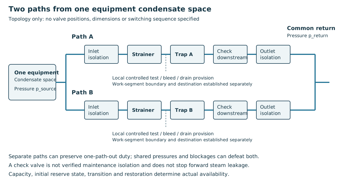
*Figure 13.1. Authored functional topology for two paths draining one equipment condensate space to a common closed return. Each path has its own isolation, strainer, trap and downstream check function. Local test/depressurization provision and access belong to the actual maintainable assembly. The drawing specifies neither valve positions, component dimensions nor a field switching sequence, and it does not establish automatic standby action. Shared source and return pressures remain common causes. [Structured topology, states and capacity examples](assets/C12/c12-parallel-trap-paths.json) accompanies the figure.*
#### Make the maintenance configuration demonstrably available
A blocked strainer/closed trap can accumulate condensate, reduce heat transfer and cause damaging liquid movement. An open-failed trap can pass live steam into the return, raising temperature, steam loading and backpressure. Its downstream check limits reverse flow but neither stops forward leakage nor verifies maintenance isolation. Identify and isolate the failed path before crediting a healthy sibling.
Shared debris, closed/obstructed common inlet, flooded or overpressured return, lost driving pressure, freezing and common maintenance errors can defeat both paths. Strainer cleanout and removal access must leave the other live path and its supports/boundary undisturbed.
An isolated standby is unavailable until its actual detection/changeover interval and condensate accumulation are acceptable. Cold retained water or obstruction can cause thermal/liquid transients during changeover. One-path-out capacity and transition behavior both constrain the arrangement.
Maintenance isolation must address equipment pressure, return pressure and hot trapped liquid, with controlled depressurization/drainage to a suitable destination and means to verify no repressurization. Closed valves can create additional pockets. Resolve access, flash discharge and adjacent live-boundary integrity through [verification](#chapter-c18) and [intervention](#chapter-c20).
A globe-valved bypass or separate drain does not discriminate condensate from live steam. Establish duty, receiving pressure/capacity, steam loss, discharge destination, monitoring and permitted duration as a separate operating state. Restoration must prevent a bypass defeating the trap. Verify drainage and absence of unacceptable steam leakage at relevant loads/pressures, observing the common return; a hot outlet alone is inconclusive because hot condensate and flash steam can be normal.
If remaining capacity, isolation, receiver loading or changeover cannot support continued service, plan equipment interruption rather than credit unverified duplication or bypass operation.
### Compact the assembly without losing its operating orientation
A trap assembly spread across the floor can sometimes be replaced by a vertical-leg arrangement. A vertical tracing manifold supported from a column can preserve space for adjacent piping and people. The available thermodynamic-trap example moves the trap and strainer into the vertical leg and adds a low drain. It presents a space-saving alternative, not proof that every trap can operate in either orientation.
When assessing the compact arrangement, preserve the following for the selected trap:
Operating orientation and gravity path to its inlet.
Strainer cleanout and isolation.
Drain destination and withdrawal space.
Reducing plan area while leaving water trapped below an inaccessible strainer would exchange one layout problem for an operating problem.
A manifold's shared structure does not merge its individual circuit duties.
Identify each supply/return circuit, its valve and drain path, and keep connections accessible for tracing work and restoration.
The useful comparison is the completed installation in operation, shutdown, freezing weather and maintenance—not simply the width of a symbol. [Layout](#chapter-c04) supplies the surrounding work space and [tracing](#chapter-c14) supplies the thermal circuit basis.
Tracing requirements also retain their intervention scope. One plant-layout rule requires tracing and insulation of the flare system when the operating philosophy is to steam equipment out to flare. An exception within that same basis permits the responsible engineering authority to waive the requirement following a risk review. That is a conditional decision within a particular steam-out procedure and service basis. It does not waive an independent thermal duty, retained-water freeze protection or the consequences of exposing surrounding material to the steam-out condition.
Keep the reviewed exception with the changed arrangement and verify the duties it leaves in place.
## Give heat-transfer fluid a controlled circulation and inventory path
A heat-transfer-fluid system carries energy through a circulating liquid. Pumps deliver fluid to a fired heater or heat-recovery unit, hot supply feeds the consumers, and the cooled return completes the circuit. The fluid must remain pumpable during startup, avoid damaging film temperatures in the heater, and retain sufficient pressure at high points to avoid unintended boiling. A short hot supply route can reduce the time fluid spends at its maximum temperature and thereby limit decomposition.
The expansion vessel accommodates expansion, operating inventory and removal of inerts, residual startup water and low-boiling degradation products. An elevated return-side vessel at pump suction can provide venting and suction head. Lower placement requires provision for vapor locking, shutdown drainage/overflow and positive pressure at the highest point.
Vessel connection topology is a separate choice from its elevation. For an HTF arrangement adopting full flow through the expansion vessel:
Route the circulating return through the vessel.
Design both vessel and connecting piping for that flow.
Fluid then passes through the inventory and degassing location before reaching pump suction. A cold-fluid vessel connected by a single leg is a distinct alternative. The main return bypasses the vessel, so the connection cannot be credited as a full-flow degassing path. Under this design basis the single-leg alternative requires specific project-authority approval.
It must retain the required expansion, venting, suction and pressure functions through its own evaluated arrangement. It is not an interchangeable simplification of the full-flow connection.
Suction margin depends on the fluid as it exists in service. Aged fluid or material absorbed from a connected disposal system can have a different vapor pressure from fresh supplied fluid. The hottest or most degraded relevant state can therefore reduce available NPSH.
Establish pump requirements and the operating level/elevation accordingly.
[pump systems](#chapter-c05) develops the suction and pump behavior.
Heat demand can fall while the heater still requires a minimum fluid flow to avoid excessive film temperature. A bypass or spillover arrangement preserves circulation as consumers close. A fired heater can reduce firing only to its available turndown. A heat-recovery unit may have little control over the incoming heat. A trim cooler or another defined heat sink must then reject the surplus.
The circulation, heater and consumer controls have to be considered together rather than sized as independent line branches. A hot standby circulation pump also avoids exposing a cold machine to sudden hot duty.
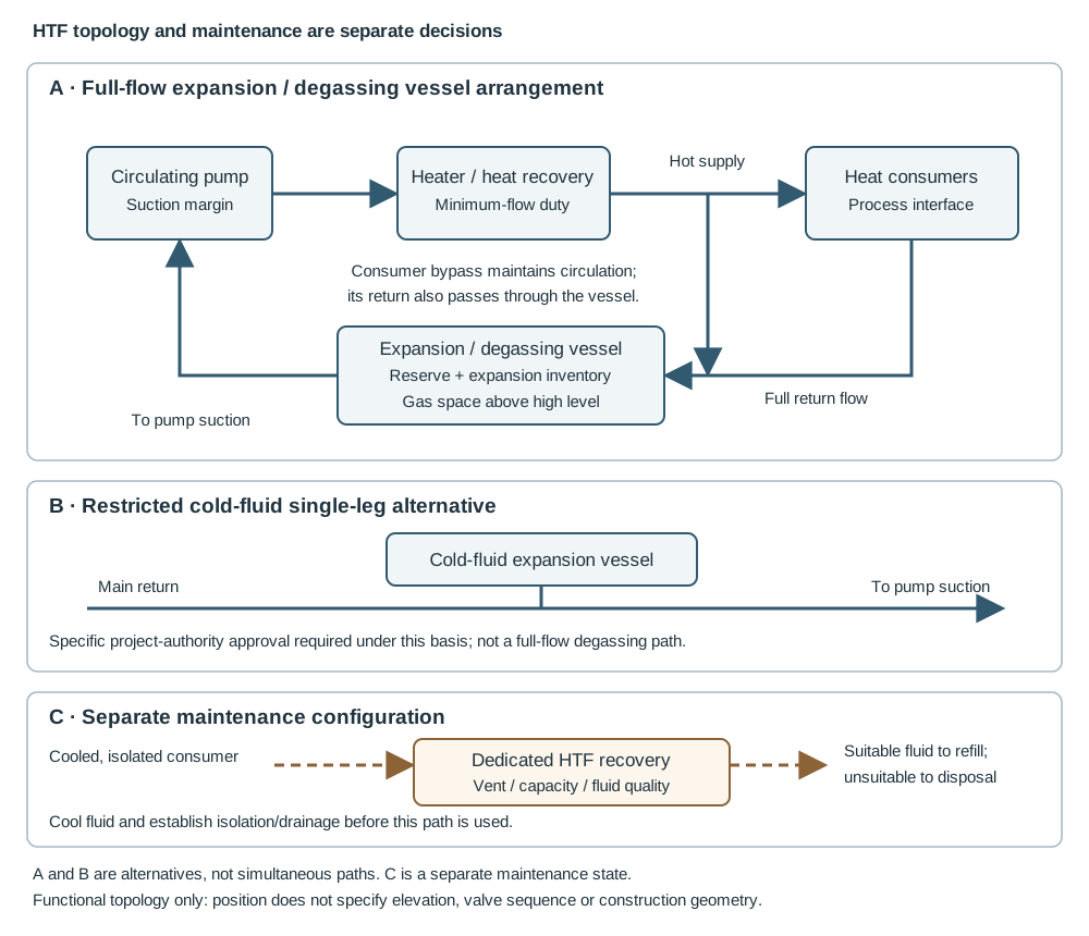
*Figure 13.2. An authored functional schematic. Panel A shows the full-flow return through the expansion vessel. Panel B shows the restricted cold-fluid single-leg alternative separately; the two panels are alternative topologies, not simultaneously installed paths. The dashed path in panel C represents a separately established maintenance configuration after cooling and isolation. The drawing does not specify nozzle elevations, valve line-ups, automatic controls or construction dimensions. A dedicated recovery destination avoids mixing the fluid with unrelated plant drains. The structured companion records the functions and states: [HTF configuration data](assets/C12/c12-htf-functions.json).*
### Test whether blanket pressure actually supplies suction margin
Fresh-fluid vapor pressure can give a misleading pressure-head credit when degradation products or material absorbed from the connected disposal system are present. A particular HTF suction-assessment method addresses that uncertainty by assuming, at normal operating temperature, that the fluid vapor pressure equals the expansion-vessel pressure. This is an adopted assessment premise for the aged/contaminated fluid. It is not a law that every HTF has that vapor pressure or that every increase in blanket pressure changes it equally.
For a simplified vessel-to-pump liquid-column assessment,
\[
\mathrm{NPSH}_a=\frac{p_{vessel,abs}-p_{vap,abs}}{\rho g}+z-h_L.
\]
In this equation, both pressures are absolute and use Pa. \(\rho\) is liquid density in kg/m³, and \(g\) is m/s². \(z\) is fluid-surface elevation above the pump reference in m. \(h_L\) is suction-path loss in m of that liquid. This expression assumes the stated surface-pressure and elevation references.
This is not a complete calculation for all inlet geometries. Under the selected equal-pressure premise, the pressure term cancels: blanket-pressure increase supplies no suction credit without a justified different fluid-pressure relationship. Low-low level, elevation and suction losses must meet pump-required NPSH and the adopted margin over relevant temperatures/degraded states. Expansion volume does not answer that suction question. [Pump systems](#chapter-c05) and [structured assessment premise](assets/C12/c12-enrichment-methods.json).
### Size operating inventory by its purpose
Thermal expansion is a change in fluid volume. For a fixed mass whose cold and hot densities are known,
\[
\Delta V_{\mathrm{exp}}
=V_c\left(\frac{\rho_c}{\rho_h}-1\right).
\]
In this equation, \(V_c\) is the total fluid inventory expressed as its volume at the minimum temperature in m³. \(\rho_c\) and \(\rho_h\) are fluid densities at the minimum and maximum temperatures in kg/m³. The equation follows from conservation of mass. It assumes the same retained mass at both temperatures and is an educational means of calculating the expansion volume used by the vessel-sizing method. It does not replace the actual fluid-property data or account for process ingress.
For an expansion-vessel procedure using a 20% addition to thermal expansion, the volume between low and high operating levels is
\[
V_{L\rightarrow H}=1.20\,\Delta V_{\mathrm{exp}}.
\]
This procedure also assigns 25% of the total vessel volume to the inventory between low-low and low levels. It verifies pump suction margin at low-low level and the relevant temperatures. It reserves space above high level for gas–liquid separation and nitrogen. These quantities have different bases. 20% multiplies the expansion volume, whereas 25% multiplies vessel volume.
Adding the percentages together or treating their remainder as an automatically adequate vapor space would lose the method's meaning.
Total vessel sizing must additionally meet low-low inventory/suction requirements, inlet behavior, gas separation and credible upsets.
An HTF storage tank serves another function: it receives fluid removed from the circuit. One procedure requires full drainable inventory plus 10% makeup allowance. The tank's other geometric and operating requirements still need assessment. This is a storage allowance, not the expansion-vessel allowance. Parallel trains can justify storage for one train only when simultaneous drainage of more than one train is excluded by the actual maintenance plan. Similarly, a dedicated maintenance collection vessel is sized for the largest consumer or group that may be taken out of service together.
### Account for pressure ingress, drying and recovery
An exchanger joins two systems separated by a heat-transfer boundary. If process working pressure exceeds HTF working pressure, a tube failure can displace HTF and introduce process fluid into the circulating circuit and expansion vessel. The working-pressure relationship can be opposite to the design-pressure relationship.
Review the actual credible pressures and the flow path remaining through valves to the expansion vessel.
Where isolation interrupts that path, the higher-pressure design or local protective alternative needs its own evaluation. Expansion volume alone does not establish overpressure protection. [Pressure protection](#chapter-c08) supplies the broader method.
Initial commissioning must deal with water left from construction or testing. High and low points, including those inside equipment isolation valves, need usable vents and drains. Drying and startup need a route for water and gas removal. Fluid returned after maintenance must also be suitable for reuse. Mixing an aged or contaminated drain inventory with clean spare fluid can destroy the replacement inventory.
Sampling and disposition therefore precede a return to common storage when contamination is credible.
A dedicated closed HTF maintenance drain can recover cooled fluid for reuse or controlled disposal while reducing spillage. Under an arrangement using buried gravity drainage to a collection vessel, hot fluid must first be cooled. The drain is intended for cooled maintenance fluid. If gravity flow cannot be achieved, an aboveground nitrogen-assisted alternative may be considered with a suitable vent destination and pressure evaluation. The collection system must remain separate from other plant drains under that adopted arrangement.
Nitrogen blanketing limits air and moisture ingress but introduces a vent and atmosphere-control duty of its own.
Provide a practical means of returning suitable fluid, filling containers or disposing of unsuitable inventory.
Viscous fluid in a cold collection vessel may need heating to be pumpable. Fresh makeup can need controlled drying and removal of light ends. These functions should be arranged so that draining, conditioning and refilling preserve the required fluid state rather than merely move liquid from one vessel to another.
## Preserve air quality and reserve at the farthest consumer
Instrument air carries control and protective action as well as pressure. The quality path starts at the intake. A compressor drawing contaminated air can distribute toxic, corrosive or flammable material. An intake filter or an oil-free compressor does not solve every gaseous contaminant. Compression, cooling and water separation remove different problems from drying and final filtration.
Cooling before the dryer reduces the water load. Separators remove liquid carryover. Desiccant drying removes moisture to the specified dew point. Afterfilters prevent desiccant particles from entering instruments.
The dew-point basis matters. A system adopts a requirement that dew point at operating pressure be at least 10°C below the lowest expected local ambient temperature. Under that requirement, a cold exposed branch is part of the assessment even if the dryer building is warm. A dew-point statement at atmospheric pressure is a different condition and cannot simply be substituted without conversion.
Increasing dryer capacity is also insufficient if liquid water bypasses the separator or a damaged filter carries particles downstream.
Desiccant drying alternates drying with regeneration and cooling. Regeneration can use heated air at atmospheric or operating pressure, or a heaterless process. The choice affects heat supply, valves, sequencing, own air consumption and maintenance. One design basis gives illustrative own-consumption ranges of 2–3% by mass for a heated atmospheric regeneration stream taken from dryer output. This compares with 10–15% for a heatless dryer.
These ranges belong to those configurations. They are useful when comparing compressor demand, rather than a universal correction for every dryer. Rapid depressurization can damage or fragment desiccant, and switching a regenerated bed before appropriate cooling changes delivered air temperature.
Monitor outlet moisture and filter differential pressure so deterioration becomes visible in the delivered function.
Estimate consumption from the actual positioners, actuators, enclosure purges, essential cooling/purging and accepted industrial users. A procedure allowing 30% for data uncertainty and early additions gives \(Q_d=1.30Q_{\mathrm{estimated}}\), with both flows expressed on one stated reference pressure and temperature basis. This allowance does not automatically include dryer-regeneration demand or usable reserve during compressor failure.
A buffer vessel carries supply from duty-machine failure until the standby source becomes effective and damps load/unload fluctuations. Its usable inventory lies between the initial pressure and the minimum acceptable delivery pressure, after distribution losses.
Establish the interval from real starting behavior.
Include the case in which an automatic start fails and manual starting is required.
A receiver with the right nominal volume but too low an initial pressure does not provide the claimed reserve.
Locate and connect the receiver so its air remains available to the intended consumers during the failure.
Provide drainage and maintainable isolation without defeating that function.
Architecture must match the maintenance pattern. A single header can be appropriate where the entire facility stops for the relevant overhaul and air interruption is permitted. Partial shutdown can require a second header or a ring-main arrangement with isolation that preserves supply to operating sections. Ring geometry alone does not prove continuity: the valve configuration and remaining supply path determine it. A pressure-drop calculation must include the most remote consumer at the required demand, not only the nearest branch.
### Keep optional demand from consuming essential reserve
Tool and industrial air can impose large intermittent loads and provide contamination or backflow paths. Under an arrangement sharing a supply plant:
Keep these downstream systems separated.
Include their accepted demands in capacity.
As pressure falls, give instrument air priority.
Mobile compressors can be a better source for a large overhaul tool demand than permanently enlarging the plant air system solely for that short condition.
Priority air for essential utility and process sections is a further distinction. Section isolation under falling pressure can preserve upstream supply to those functions. Its sequence and setpoints must match the actual consumers and reserve. An individual valve required to act after general air failure can need a secured local buffer supplied through a non-return arrangement. That buffer must be assessed for the valve's actual consumption and required duration.
It should not be credited to every instrument merely because it is drawn somewhere in the network.
Breathing air is a separate service-quality and reliability question. The preferred arrangement in this utility design basis uses separate bottles for breathing equipment. Where a project adopts shared supply, the breathing-air standard, intake contamination checks, filtration, dedicated connections and guaranteed availability need explicit provision. Ordinary instrument-air cleanliness and pressure are insufficient evidence for that use. The same guidance excludes nitrogen and carbon dioxide as backup gases for the instrument-air network.
This restriction must remain explicit when that design basis applies.
During construction and maintenance, keep water, oil, cleaning fluids and debris from the distribution system. One instrument-air procedure specifies compressed-air pneumatic testing and air blow-through, and excludes liquids and other gases for that work. Adopted as such, it cannot be replaced by the usual hydrotest sequence simply because the piping material is metallic. [Testing, cleaning and readiness](#chapter-c18) develops test safety, boundaries and restoration. The local moisture and contamination consequences still govern this utility.
## Separate supplied water, collected drainage and uncontrolled spills
Fire water, cooling water, process water and potable water have different duties. Cooling-water supply and return form a heat-removal circuit. The arrangement must serve exchanger locations without defeating access or crowding other buried services. Fire-water routing and isolation must preserve the required emergency coverage while a section is out of service. Water-service identity also determines contamination and disposal concerns.
A convenient spare connection is unsuitable if it creates an unassessed cross-connection between distinct functions.
### Nominal reach does not remove a structural shadow
A monitor can have nominal range sufficient to encompass an equipment location while a process structure blocks the required path to it. The target's position inside a range outline therefore answers only part of the placement question.
Trace the monitor-to-target approach against actual structures, equipment elevations and accessible deployment positions.

*Figure 13.3. The ground position has an obstructed path to the air-cooler target. The elevated candidate has a different approach above the intervening structure. These lines show physical visibility and obstruction, not water trajectories, range or accepted coverage.* [Structured obstruction and deployment alternatives](assets/C12/monitor-obstruction-geometry.json).
An elevated candidate can address a structural shadow while introducing support, vendor-equipment, access and maintenance requirements. Another ground position or additional monitor can address a different target or approach.
Examine those alternatives against the complete target arrangement.
Improving the path to one air cooler does not establish coverage of adjacent equipment or a tall vessel.
A historical nominal-range comparison uses 150 psi nozzle pressure and 500 gpm, with a prevailing-wind qualification that has no numerical wind value. Those conditions do not establish a universal effective reach, and no range curve is reproduced or interpolated here. The actual nozzle, pressure, pattern, weather and target requirements must establish useful coverage.
For any selected elevated installation, preserve structural support, freezing conditions and reachable servicing positions.
Do not treat the elevation sketch as a firewater supply design.
Buried and aboveground cooling-water routes offer different tradeoffs. An underground header near exchanger channel ends can shorten laterals and preserve rack space. Aboveground routing improves direct access but can enlarge the rack and lengthen branches. Ground separation between hot return and cool supply limits unwanted heat transfer through soil. The useful distance depends on the adopted arrangement.
Foundation crossings and excavation space belong in [buried-system routing](#chapter-c11), while channel removal and equipment access connect to [exchanger arrangement](#chapter-c06). These interfaces should be resolved while the plot is still adaptable.
Gravity plant drainage separates streams by what they can contain and where they may go. Contaminated surface water and oily equipment drainage need the relevant hydrocarbon-recovery or treatment route. Chemically aggressive streams can need separate collection and neutralization or recovery. Sanitary drainage has another destination. Combining streams saves some pipe but can enlarge the treatment duty and introduce incompatibilities.
The design decision should include the receiving facility and credible rain/fire-water demand, rather than end at the edge of the process area.
A closed hydrocarbon drain collects intended releases from equipment while retaining containment. An open drain collects liquids reaching floors or paving. A sump that conveniently collects drips is not automatically complete secondary containment for a major inventory release.
Define its collection area, credible release volume, free capacity, alarm, removal capacity and access during an incident.
Pumps, vacuum connections and disposal routes differ between small maintenance drips, a substantial leak and a catastrophic release.
In one modular-facility architecture, frequent drains are hard-piped to a closed header, then to a low-pressure knockout drum for degassing and onward to slop storage. Equipment is drained within the process as far as practicable before final drainage. Positive separation at a blind or removable spool prevents the maintenance drain connection remaining an unintended process connection in normal service. Restriction devices limit the inflow where needed, but the header and receiver still need evaluation for gas blow-by. A high-pressure source does not become harmless once its first liquid inventory has left.
That architecture keeps aerated floor-sump liquid from the closed hydrocarbon collection path and provides a separate removal destination. It also recognizes that air-compressor and dryer packages continuously discharge water condensate and need suitable nearby collection. These are conditional choices for a defined modular installation. They explain why aeration, contaminants, frequency, pressure and receiving capacity govern segregation. They do not establish that every plant drain should enter a flare knockout drum or that every compressor condensate stream belongs in sanitary treatment.
An assisted equipment drain using nitrogen or fuel gas creates another pressure and gas-loading case.
Confirm the assisting medium's compatibility, the available pressure and the receiver venting.
Confirm the possibility of continuing gas flow after liquid removal.
Hoses and temporary collection connections also change the configuration. Their rating, restraint, connection security and reinstatement need attention. The physical branch detail and isolation integrity remain linked to [vent and drain connections](#chapter-c07) and the service hazards to [hazardous-service mechanisms](#chapter-c13).
### A supply break can move the hazardous-release boundary
A utility connection must be evaluated in its connected and disconnected states. A removable or turned spool with the required closure creates positive separation after an intermittent washing, steaming or blowing duty. A frequently used connection can have a separately selected blind arrangement. Neither provides continuous pumped injection in its disconnected state. The actual function and line-up matter more than a diagram's type number.
Continuous water or condensate injection into a sour process can use an intermediary break tank. It can interrupt communication back into the main utility supply while a pump supplies the process. This protects one boundary but creates another. If the pump stops and its check valve fails, process material can return through the pump into the atmospheric tank and expose nearby people to H₂S. A protected upstream supply does not establish that the pump/tank area is safe.
The adopted arrangement addresses that local path with a closed-top atmospheric tank, an elevated vent and low-pressure alarm on each pump discharge. Its particular closed-top detail requires the standpipe top at least 15 ft above the tank top.
Keep that local height reference.
It is not a generic safe-dispersion distance or an air-gap dimension. Vent destination, process pressure, release composition, tank/pump materials and the response to loss of injection still need their actual assessments. An alarm reports a condition and does not itself stop process backflow.
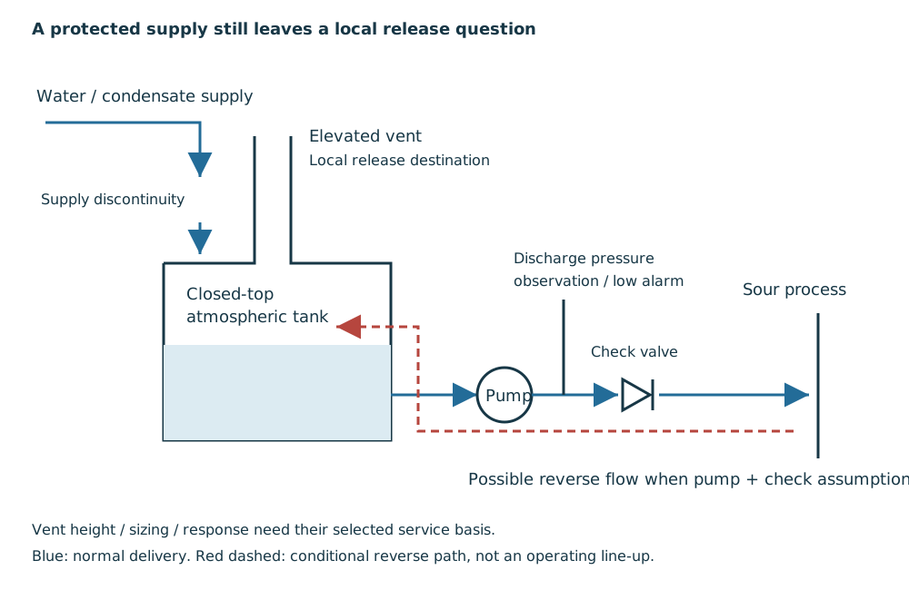
*Figure 13.4. Authored functional diagram of the selected continuous-injection alternative. Blue arrows show normal water delivery; the dashed red path shows possible reverse process flow when the pump and check-valve assumptions fail. The supply discontinuity and the tank vent are separate interfaces. The sketch gives no air-gap size, vent sizing, trip architecture or qualified dispersion distance. [Structured functions and failure conditions](assets/C12/c12-utility-break-boundary.json) accompanies the diagram.*
The same method prefers low-hardness water or condensate to limit calcium deposits that can plug the injection path. That water-quality duty is separate from positive isolation and from the H₂S release consequence.
When injecting into a pressurized system, verify forward injection pressure near the process connection.
Reassess loss of flow, check-valve behavior and venting through actual operating and shutdown states.
[Sour-service mechanisms](#chapter-c13), [pressure protection](#chapter-c08) and [measurement interfaces](#chapter-c22) provide the related questions without converting this local arrangement into a universal utility safeguard.
## Carry the product without losing its quality or the transfer function
Transfer facilities include light-product truck terminals, service-station distribution, aircraft fueling, lube blending and asphalt handling. Their common piping elements do not erase the product and operating distinctions. A light-product loading rack needs the delivered flow and pressure at the loading arm, control of spills and escape access. A station's buried tank-to-dispenser route also needs suitable containment and a practical means of locating or repairing a leak. A hot asphalt route needs temperature, pumpability and repeated startup/shutdown behavior.
An aircraft-fuel route adds stringent contamination control.
Size transfer paths for simultaneous delivery and available source pressure after pipe/component losses to the actual loading arm or dispenser.
Pump shutoff pressure is a containment/protection condition even when the normal transfer pressure is lower. Different products and their flow limits can govern separate cases. An historical terminal throughput is not a transferable design capacity for a new rack. [System definition](#chapter-c01) and [pump performance](#chapter-c05) supply the broader flow and pump methods, while [metering and control](#chapter-c22) explains measurement accuracy and control conditions.
Layout affects both operation and intervention. Overhead rack piping can keep transfer connections visible and reduce exposure of buried leaks to groundwater, but needs access and support. Loading arms require crossover space and drivers need clear escape lanes. Direct buried routes at small stations can reduce pipe length and containment extent, yet metal components, protective coatings and the secondary-containment geometry must be compatible. A surrounding containment structure can obstruct cathodic-protection current.
Containment and corrosion protection cannot be specified independently.
### Follow the second boundary through the buried-to-aboveground transition
A secondary-containment trough surrounds the product piping with another physical boundary. In the illustrated station construction, trough sections connect the tank area to the dispenser blocks, and the product pipes rise within the block containment to the dispenser connections. The rise is part of the containment interface. A sound buried trough does not establish continuity around the riser or the penetration where piping enters the dispenser.
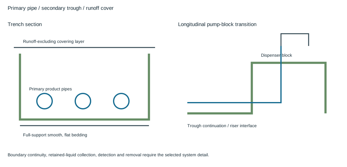
*Figure 13.5. The section distinguishes the primary product pipe, the surrounding trough, its full-support bedding and a covering layer that excludes surface runoff. The longitudinal inset follows the trough into the dispenser-block containment as the product pipe rises. No capacity, leak-detection or current containment acceptance is assigned.* [Structured boundaries and interfaces](assets/C12/station-trough-interface.json).
Runoff exclusion and product containment have related but different purposes. Water entering the trough can consume available volume, conceal a leak or complicate inspection and removal. The covering layer addresses that intrusion route. Its joints, edges and penetrations need the selected construction detail. Smooth, flat bedding supports the trough through its length.
Local voids or hard points can change its support and loading even when the product pipe inside it is adequately supported.
The trough must have an identified means of collecting, observing and removing any retained material.
Trace low regions, interconnections, accessible observation points and the receiving destination for removed liquid under the selected system basis.
A continuous-looking channel does not prove drainage, capacity or leak detection.
Keep the containment assessment with the primary piping, its joints and the tank/dispenser transitions.
Do not treat the trench as independent civil work.
Material and corrosion protection also meet at this interface. The represented historical form uses fiberglass troughs and a polypropylene covering sheet. Its sheet thickness and bedding detail are construction-specific rather than universal material or strength criteria. Metal parts in a buried system require their selected protective arrangement, and a containment structure can interfere with the path for cathodic-protection current. A sealed protective boot around a metal flexible connector serves a different local purpose from the surrounding trough.
Verify compatibility, inspectability and protection of the actual parts through [materials](#chapter-c02), [external protection](#chapter-c15) and the selected containment basis.
### Read a loading arm in both elevations
A loading-rack side elevation locates the separate product risers and arm pivots along the working line. An end elevation then shows how an overhead product route, its vertical connection and the arm's horizontal and vertical reach relate to the vehicle connection and working zone. The same pivot and connection must be identifiable in both views. An arm that reaches a point in one projection can still miss it in the other or pass through an occupied working space.
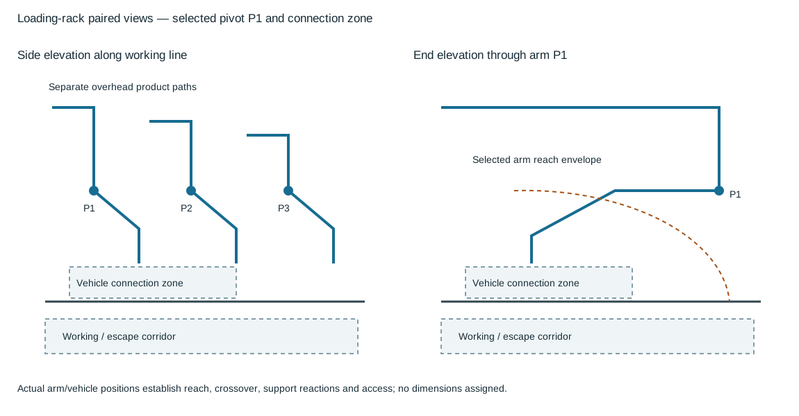
*Figure 13.6. The paired views retain overhead product supply, the selected arm pivot and the vehicle connection zone. Dashed arcs denote a reach envelope to be established for the actual arm; their radius is not a certified reach. The working/escape corridor remains separate from the arm connection geometry.* [Structured paired-view interfaces](assets/C12/loading-rack-geometry.json).
Overhead supply can keep product connections visible while requiring a defined support and access arrangement. A vertical drop changes the elevation of the product path. The loading arm then articulates from its pivot to the selected vehicle interface.
Preserve product segregation through the risers and arms.
Similar arms beside one another do not establish an interchangeable product connection, and common supporting steel does not authorize a common fluid path.
Examine the arm in its stowed, connecting, transfer and disconnected positions against the selected vehicle range.
Adjacent arms need their intended crossover space, while the driver's escape and personnel access routes must remain useful with the arms in those positions.
Include vehicle positioning, coupling handling, overhead obstructions, moving envelopes and the support reactions.
The actual loading arm, nozzle and site information establishes these relationships. Historical nominal dimensions do not certify reach or escape clearance. The consumer hydraulic basis remains attached to the selected connection rather than inferred from the drawing's height.
### Product delivery, tank breathing and returned vapor use different paths
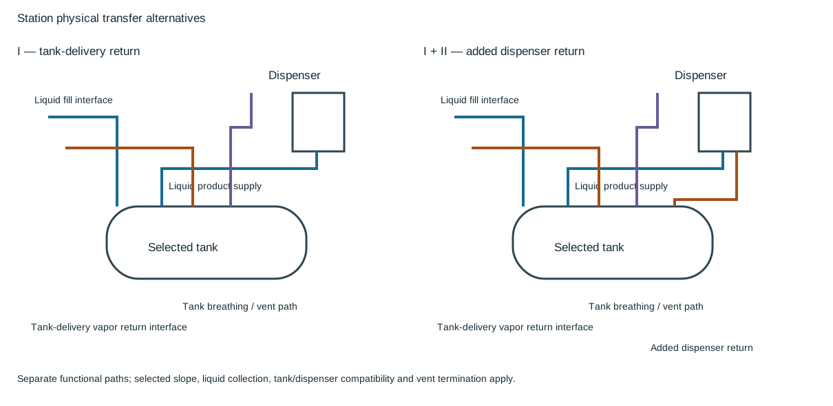
*Figure 13.7. Alternative I identifies the liquid fill, product supply, tank vent and tank-delivery vapor-return interfaces. Alternative I + II adds a separate dispenser return to the selected tank connection. They are independent functional alternatives, not instructions to add recovery piping to every station. Vent endpoints are selected-design interfaces, without permission for unrestricted release.* [Structured transfer alternatives](assets/C12/station-transfer-paths.json).
Tank-delivery vapor return and dispenser vapor return originate in different transfer activities. The first connects the tank vapor space to the selected delivery interface as liquid enters the tank. The second begins at the dispenser's selected vapor connection and returns through its own branch or manifold to the identified receiving tank connection. A line labeled vapor must not be assumed to serve both functions, or to replace the breathing path, without the actual compatible system design.
Buried horizontal routes and aboveground risers also have different geometric duties. The riser reaches an accessible aboveground connection. The buried route needs its selected slope and collection relationship so retained liquid does not defeat the intended vapor or product path.
Inspect crossovers in section, including fitting envelopes and their effect on slope.
A drawing showing an apparent continuous fall in plan supplies no elevation evidence.
Keep the receiving low point and destination explicit, with the appropriate inspection and liquid-removal basis.
The depicted installation alternatives were developed with composite steel tanks and particular dispenser constructions. Fiberglass-tank piping was described as similar, with the actual tank and dispenser selected by the plans. Similar topology is not automatic material substitution or interface compatibility. Recovery equipment, dispenser fittings, joint construction, vent termination and the applicable emissions/containment requirements need the adopted contemporary basis. These physical paths establish the configuration questions.
They do not establish recovery efficiency, a universal vent-release permission or an operating lineup.
For aircraft fuel, filtration, water separation, draining low points and protecting hose/sample connections with dust caps preserve delivered cleanliness. A jet-fuel material basis admits carbon steel or stainless steel and excludes copper alloys, galvanized iron and cadmium-plated wetted parts. Under that basis, instruments and connectors need the same compatibility review as the pipe. Small-airport fiberglass systems described for other aircraft-fueling uses do not override the stated jet-fuel material rule. Product identity must remain attached to the local selection.
# Chapter 14 — Hazardous and cleanliness-sensitive services
## Describe the medium and the state that creates the hazard
Material, joints and safeguards must match composition, phase, coincident pressure/temperature, contaminants and surrounding atmosphere during operation, testing, opening and repair. Closed sour piping, air-exposed sulfide deposits and wet restart conditions pose different damage/release mechanisms. Removing oxygen does not itself create a personnel-entry atmosphere. [Materials](#chapter-c02), [joints](#chapter-c03), [readiness](#chapter-c18) and [condition assessment](#chapter-c19) supply the general methods.
## Oxygen compatibility depends on ignition as well as corrosion
Many metals can burn violently once ignited in an oxygen atmosphere. Ignition prevention depends on the energy supplied locally, the material's ignition and combustion behavior, and its ability to dissipate heat. A long smooth pipe and a small valve internal do not present the same problem. Thin elements have less material through which to spread heat. Rough edges, particle impact, friction and turbulent high-velocity regions create local ignition concerns.
Oil, grease and organic residues can ignite and promote combustion of adjacent metal. Dust, scale and weld particles can be accelerated into a fitting or valve. Smooth internal surfaces, rounded edges, removal of contaminants and restraint of local velocities address different parts of that mechanism. Good corrosion resistance alone does not establish oxygen compatibility.
Nonmetallic seals and lubricants require proof for the actual oxygen pressure and temperature. Reducing their volume and surrounding them with metal can improve heat dissipation. These measures do not establish that an unqualified material is suitable.
The following material choices illustrate a specifically restricted dry-gaseous-oxygen design criterion. They apply only where the project adopts that criterion. Its −20°C to +150°C range bounds the application but does not by itself select a material. Within that criterion, carbon steel, specified austenitic stainless steels and selected nickel or copper alloys have different applications.
The carbon-steel account includes exclusion of water condensation and noncorrosive contaminants, rigorous cleaning and protection during shutdown. Its particular in-plot application is limited to operating temperatures below 90°C. The associated pressure–velocity chart identifies a carbon-steel category up to 100°C. That chart category does not remove the narrower in-plot condition. Location, temperature and component duty all remain part of the selection.
Specified austenitic stainless grades can make internal cleanliness easier to maintain. External pitting and chloride stress corrosion remain relevant. Within that specifically adopted criterion, higher-chromium grades and duplex stainless steels shall not be used for the specified oxygen application.
Selected nickel alloys provide improved ignition resistance in critical high-velocity or impingement regions. Their exact composition and external environment still matter. For example, an alloy used for its oxygen behavior can have a separate steam-environment cracking concern. “Nickel alloy” describes a family, not a complete material specification.
Aluminum illustrates the importance of scope. It is excluded within this dry-gas temperature basis because its ignition and combustion behavior can produce severe failure. Its established use in cryogenic oxygen-producing equipment is a different application. A material decision for that equipment cannot be copied into an ordinary gaseous-oxygen line. The ordinary line's prohibition cannot be extended silently to the cryogenic installation.
### Calculate the local velocity before applying its material rule
Average velocity uses the design maximum flow and the actual internal area at the section being assessed:
\[
v=\frac{Q}{A},\qquad A=\frac{\pi D_i^2}{4}.
\]
Here \(v\) is average velocity in m/s. \(Q\) is oxygen volume flow at that section's actual pressure and temperature in m³/s. \(A\) is internal flow area in m², and \(D_i\) is internal diameter in m. A standard-volume flow requires conversion to local conditions before division by installed area can give local velocity. Nominal size is not the measured internal diameter.
Restriction and throttling velocities can exceed the upstream average; evaluate the actual local passage against the material criterion.
### Read the pressure–velocity regions with their conditions
Figure 14.1 recreates the two high-pressure curves numerically and retains the separate low-pressure regions. Its horizontal coordinate is pressure in bar(g), meaning gauge pressure. This chart coordinate differs from the absolute pressure needed when a gas-property or standard-to-actual-volume conversion requires an absolute reference.
Before comparing the point, establish local flow and pressure on their respective bases.
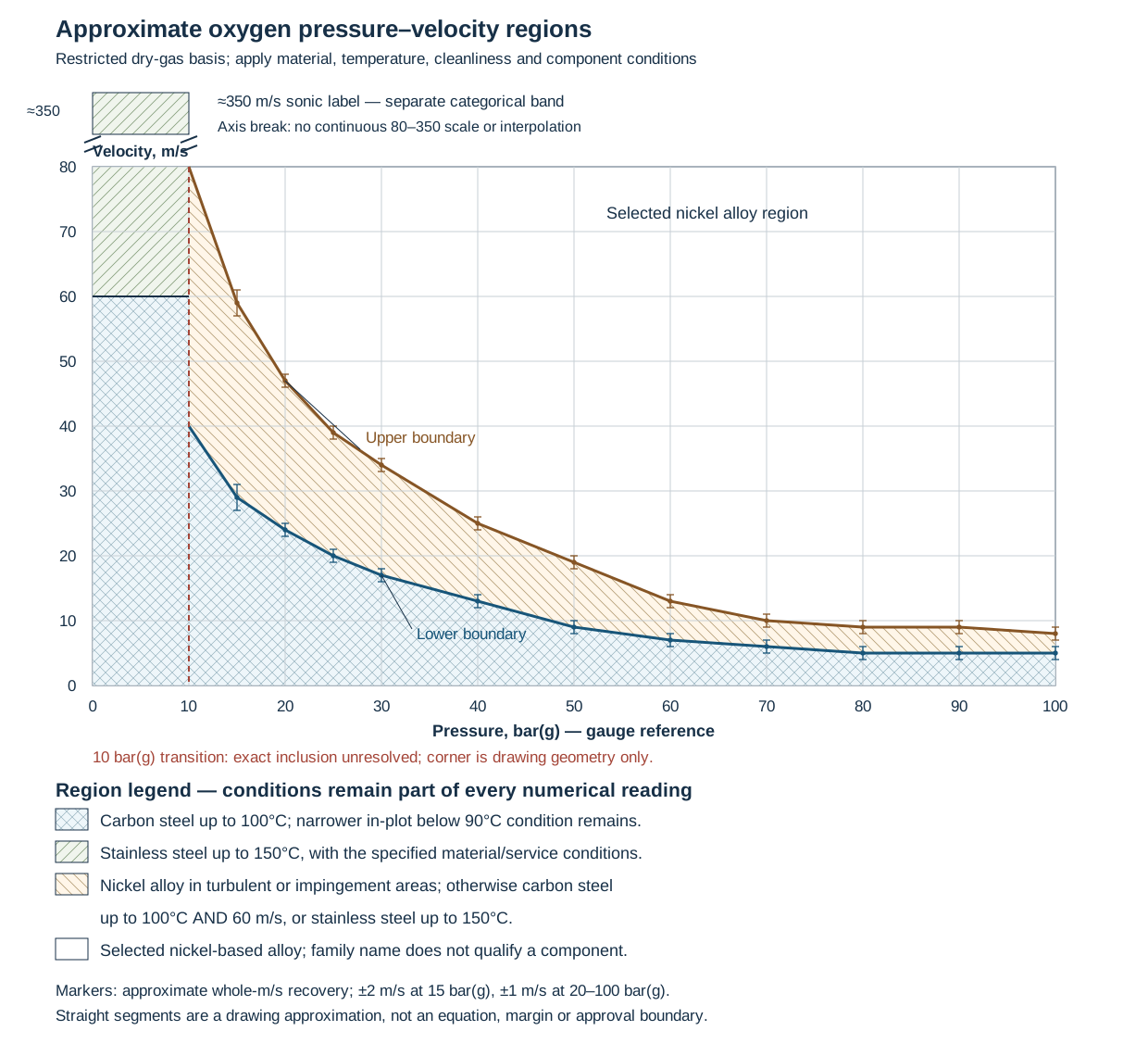
*Figure 14.1. Approximate graphical recovery for the specifically adopted dry-gaseous-oxygen criterion. The lower and upper curves define different regions; their legend is part of the method. The low-pressure categories and approximate sonic ordinate are shown separately, with a broken velocity axis. Markers have estimated graphical reading allowances, not operating tolerances or design margins. [Recovered numerical data, region conditions and reproducible drawing definition](assets/C13/c13-oxygen-pressure-velocity.json) preserve the quantities, uncertainty and discontinuities; [drawing implementation](assets/C13/c13-oxygen-pressure-velocity.draw.py) reproduces this native figure without a raster background.*
At pressures above the approximately 10 bar(g) transition, the crosshatched region below the lower curve is the carbon-steel category up to 100°C. Between the curves, the legend calls for selected nickel-based alloy in turbulent or impingement areas. **Otherwise** it permits carbon steel up to 100°C **and** 60 m/s, or specified stainless steel up to 150°C. Above the upper curve is the selected nickel-alloy category.
The two curves are not simply universal carbon-steel and stainless-steel maximum velocities. Component duty and the complete legend distinguish the alternatives. The particular carbon-steel in-plot temperature condition remains below 90°C even where the chart says 100°C.
Left of the approximately 10 bar(g) transition, the chart instead shows carbon steel up to 60 m/s. A separate stainless-steel region extends to the labeled approximate sonic velocity of 350 m/s. That upper label is a categorical endpoint on a broken ordinate. It is not a continuous extension of the 0–80 m/s scale or a universal sonic speed for every oxygen condition. Do not extrapolate either high-pressure curve into this region.
The exact inclusion convention at 10 bar(g) is not established here. Neither the endpoint drawing nor interpolation grants permission at that boundary. The numerical recovery stops at 100 bar(g), where the drawn curves stop.
*Table 14.1. Approximate high-pressure boundary readings. Values are in m/s; the ± quantity is an estimated graphical reading allowance at the stated gauge pressure.*
| Pressure, bar(g) | Lower curve, m/s | Upper curve, m/s |
| --- | --- | --- |
| 20 | 24 ± 1 | 47 ± 1 |
| 30 | 17 ± 1 | 34 ± 1 |
| 50 | 9 ± 1 | 19 ± 1 |
| 100 | 5 ± 1 | 8 ± 1 |
The structured companion supplies additional sampled ordinates. Whole-m/s reporting and the indicated allowance reflect line width, graphical reading and rounding. The allowance is larger at the steep 15 bar(g) sample. Straight lines between samples reproduce an approximate drawing, not an exact pressure–velocity equation. A point near either curve requires a better-established controlling boundary and treatment of uncertainty. A displayed equality cannot resolve material eligibility.
For a project adopting the same restricted pressure–velocity criterion, its straight-pipe category includes bends only when their radius is at least 5D. Retain the criterion’s pipe-diameter notation D and the radius/diameter convention of its bend detail for this check. The label “long-radius” alone does not establish that geometry. Do not substitute the separately defined internal diameter \(D_i\) used in the flow-area calculation without establishing the same measurement basis. Particle-impingement fittings, valve internals and the region downstream of a control valve remain distinct critical regions.
The criterion calls for selected nickel alloys in these critical regions. Within the chart areas allowing carbon or stainless steel, it also describes an alternative using those materials at half the stated velocity limit. These are conditional material/velocity alternatives, not a rule that halving any flow makes any fitting safe. The downstream region extends at least ten nominal pipe diameters under this basis. Actual local geometry must remain consistent with its intended function.
Filters show a related area calculation. The following particular oxygen-filter criterion applies only where a project adopts it. Under this criterion, a filter upstream of control or measuring stations has a maximum 50 μm pore/mesh size. Its maximum entry velocity is 0.2 m/s.
A feed to a low-temperature reaction system containing flammable matter has a finer 10 μm limit. It also has a lower 0.05 m/s entry velocity.
Entry area and pore size are distinct. Filter selection also requires pressure loss, strength and particle-retention performance.
The filter must also be removable without dropping its collected particles into downstream piping. Purge-gas filtration must preserve the downstream cleanliness requirement. A spare dead-ended filter arrangement can create a place for dust to accumulate. Under that adopted filter criterion, spare filters shall not be installed. Maintenance provision should provide access and continuity without reintroducing the contaminant trap that the selection was intended to avoid.
### Remove local pockets and preserve the joint orientation

*Figure 14.2. Selected oxygen local geometry comparisons.*
A tee used only to change direction leaves a capped continuation where particles or cleaning residue can accumulate. A continuous turn removes that unnecessary pocket while retaining the intended path. This comparison belongs to the selected dry-gaseous-oxygen carbon-steel/stainless-steel construction. The bend, branch and local material still need the applicable impingement, pressure–velocity and cleanliness checks described above. Eliminating a pocket does not qualify every elbow material.
The same route places a cathodic-protection insulating flange only in a vertical line section. This avoids particulate deposition that could bridge its insulation. The selected design and materials require their adoption approval and protection against internal sparking from potential differences. A vertical installation addresses the deposition geometry. It does not by itself establish the complete electrical or pressure boundary.
The physical bypass comparison permits a position above the main pipe or in the same horizontal plane. It excludes a position below the pipe. The source-conditioned construction specifies Monel bypass piping above 2,000 kPa gauge design pressure and allows an appropriate integral valve-body bypass. Its usual maximum ¼D notation is not a universal bypass sizing rule.
Actual flow, pressure, material and velocity must establish the selected part. No control architecture follows from the orientation comparison. [Structured geometry and conditions](assets/C13/c13-oxygen-local-geometry.json) preserve these separate physical obligations.
For the remaining dimensional statements, retain each statement's own basis. Ordinary bends in this route use R ≥5D. A separate nickel-base-alloy fitting illustration literally labels an R =1.5D part as short-radius. That historical label does not settle another catalog's radius name.
Successive one-nominal-size reductions have an at-least-1,000 mm statement in the body and a greater-than-1,000 mm figure label. At exactly 1,000 mm, the adopted construction instruction needs resolution. The two statements cannot silently be treated as identical.
Vent orientation is another unresolved distinction. The body describes vertical, straight vents with conditions for unavoidable bends and curved alternatives. The annotated graphic recommends horizontal discharge to a safe location. Before fabrication, resolve the adopted vent configuration, downstream stainless-steel construction and velocity basis. The local pocket, insulating-joint and bypass comparisons do not choose between those vent instructions. [Fabrication](#chapter-c17) and [Cleanliness and readiness](#chapter-c18) carry the resolved geometry into the inspected installation.
## Establish and preserve oxygen cleanliness
Shop precleaning must be preserved through sealed storage and erection; site fit-up or welding can require post-erection cleaning. Select the combined method early enough to provide access and removal paths.
During cleaning planning, select the method early enough to permit temporary spools, access, drains, segregation and removal of cleaning agents.
The agent must be compatible with the item, its contaminants, the downstream process and the personnel/environmental conditions of its use. A residue that is harmless to one cleaning operation can contaminate or poison the receiving process.
Where the precleaned state is preserved and site welding is limited, a specified blow-through with oil-free air can address particles. Brush pigs can supplement this blow-through where appropriate. It is not a substitute for degreasing a system whose cleanliness was lost. Chemical cleaning then needs complete agent removal and drying.
A water-based rinse introduces a moisture state that can produce later rust in carbon steel. Under a particular procedure, residual-air dew point after rinsing and drying must be at least 10°C below minimum service temperature. This moisture criterion does not replace oil or particle checks.
Long transport lines present a particular problem. Cleaning liquid may be difficult to remove completely, and hydrotesting can cause subsequent rust. The selected sequence therefore joins examination, pressure testing, mechanical cleaning, displacement, drying and preservation. A permitted pneumatic alternative changes stored-energy and examination considerations rather than simply saving drying time. [Testing and cleaning](#chapter-c18) develops those system methods. Oxygen cleanliness remains an independent requirement after them.
Cleanliness inspection needs accessible evidence and a defined acceptance basis. Direct inspection can use bright white light and ultraviolet methods, together with examination for scale, spatter, fibers and organic residues. Wiping with a clean lint-free cloth or inspection of representative cleaning-fluid effluent can address surfaces that are difficult to view. Indirect inspection compares the effluent with clean unused fluid. Sampling and analysis must represent the parts being accepted. A target used during blow-through gives evidence of carried particles, rather than a complete measurement of oil remaining on every surface.
Under one adopted oxygen-cleanliness basis, allowable oil on metal is 1 g/m². The associated observations show that oil at that loading is not visibly apparent under bright white light and does not produce a detectable finger smear. Visual absence of oil is therefore weaker evidence than meeting the surface-loading limit. The same inspection procedure uses separate fluid-sample criteria: fluorescence can identify oil contamination, and an evaporated sample-residue criterion is expressed in mg/kg. A bulk-fluid concentration is not a surface loading. It cannot be converted into g/m² without a supported sampling, extraction and area relationship.
Preserve caps/seals and closed cleaning/joint-material containers; segregate oxygen tools and materials from oily work. Keep covers until joining and re-establish cleanliness after contamination.
Dry internal weld roots, smooth flow paths and retained cleanliness matter as well as external weld appearance. A clean, completed system awaiting startup needs a defined preservation atmosphere, pressure and duration, with the same controls on the gas's oil, moisture and particles.
## Preserve the oxygen design conditions while operating and opening the system
Throttling and isolation are different duties. Under the example’s specifically adopted oxygen-valve criterion, a control valve has selected nickel-alloy body/internals and a downstream high-velocity-compatible section. A separate block valve provides tight shutoff. The control valve is not credited with both duties.
Block valves operate fully open or closed. Pressure equalization precedes opening, and no oxygen flows before ordinary closing. This is a specified operating basis, with separately identified emergency and nitrogen-purge exceptions. An emergency valve needs a protected or remote operating position so its operator is not placed beside the release.
Pressurizing, depressurizing, venting and purging follow the normal oxygen-flow direction under this basis. It excludes back-blowing an installed filter. Clean nitrogen used for purging must remain at higher pressure than the oxygen system at the connection. The connection must prevent oxygen entering the nitrogen network. A low-point dead leg, an unfiltered temporary purge hose or a bypass below the main line can alter contamination behavior. Correct selection of the main pipe does not prevent these changes.
A connection to equipment containing flammable material needs separation during startup and shutdown. The available alternatives include two double-block-and-bleed arrangements in series or a pressurized nitrogen wedge in a section of oxygen piping. Their pressure, valve and vent functions require their own evaluated configuration. A single non-return valve is not a substitute for the selected separation method.
Opening introduces further states. Before oxygen-system inspection, maintenance or repair, the adopted procedure removes oxygen by venting followed by oil-free nitrogen purging. Internal inspection requires complete removal of the relevant item or clean, visible-handled spades at all connections. Personnel entry adds another condition: nitrogen must be replaced with air and ventilation maintained. Oxygen removal and positive separation do not establish an atmosphere suitable for entry.

*Figure 14.3. An authored condition map for the scoped oxygen intervention basis. The four panels distinguish operating control, oxygen removal, physical separation for internal work and the additional atmosphere condition for personnel entry. They identify conditions to establish, rather than supply a valve sequence or an entry procedure. Repair and return must restore cleanliness and the applicable component/operating basis; [structured condition data](assets/C13/c13-oxygen-states.json) retains those distinctions.*
Repair/reinstatement must preserve qualified oxygen components, joining and cleanliness, including access for inspection/recleaning before service. Ordinary lubricants, temporary seals or shop handling can invalidate that condition.
## Hydrogen selection needs a material envelope as well as a pressure rating
A process-hydrogen class can carry a familiar flange pressure class while adding a separate temperature restriction tied to material and hydrogen partial pressure. Selecting the pressure class alone loses that condition. The material, its specified product and heat-treated condition, the hydrogen exposure and the selected component limits must describe the same intended operating state. A hotter startup, a changed feed or a replacement item can change that state without changing the line's nominal size.
A specifically adopted carbon-steel hydrogen basis refers to the material's API 941 temperature limit at the applicable hydrogen partial pressure. It separately caps its class at 205°C. Its explicit rule takes the lower of those two temperature limits. The 205°C value is a local cap in that basis.
It is not a general carbon-steel hydrogen permission. Meeting it does not remove the need for the material-curve check. The applicable curve must be established for the actual material and exposure before its temperature can enter the comparison.
### Keep the two temperature constraints visible
For that selected carbon-steel basis, write the temperature comparison as:
\[
T_{\mathrm{limit}}=\min\!\left(T_{\mathrm{material}},T_{\mathrm{class}}\right),\qquad T_{\mathrm{class}}=205\,{}^{\circ}\mathrm{C}.
\]
In this equation, \(T_{\mathrm{material}}\) is the already established temperature limit from the applicable material curve at the established hydrogen partial pressure. \(T_{\mathrm{class}}\) is the separate local class cap. Both quantities are in °C and concern the same selected material/service basis. The intended exposure temperature \(T_{\mathrm{duty}}\), also in °C, must satisfy \(T_{\mathrm{duty}}\leq T_{\mathrm{limit}}\) for this temperature comparison. This step does not calculate partial pressure, establish the curve's applicability or demonstrate the adequacy of the complete assembly.
A pressure reference, composition and applicable curve edition are needed wherever the adopted material evaluation requires them. A total line-pressure value, an instrument reading or a flange class does not by itself identify the hydrogen partial-pressure input. For the partial-pressure input:
- Establish the relationship on the adopted assessment basis.
- If it is missing, leave the comparison unresolved.
- Do not infer an acceptable curve temperature from the class cap.
### Retain the conditions of the selected material family
The same class portfolio illustrates why upgrading a material name is not a complete envelope calculation. Its hydrogen classes using 1¼Cr–½Mo and 2¼Cr–1Mo specify a 595°C class cap and retain the material-curve reference. Other process classes using those alloys have different stated caps. A limit from a nonhydrogen class cannot replace the hydrogen class's 595°C condition. The 205°C carbon-steel rule and 595°C alloy-family cap remain separate adopted conditions. Neither is a universal ranking of hydrogen resistance.
Other selected hydrogen families use 5Cr–½Mo or 9Cr–1Mo with a 645°C class cap and material-curve reference. Specified austenitic stainless and nickel-alloy families have their own class, product, bolting and component conditions. The ferritic class's curve instruction cannot be transferred into every stainless or nickel-alloy selection by analogy. A higher class temperature also does not raise a lower individual component rating.
For example, a selected 321H family states a 705°C class cap. Its listed gauge-valve item has a 540°C temperature rating. The particular item remains limited by its own applicable pressure–temperature rating.
Product condition and construction details continue below the class heading. Specified normalizing, normalizing and tempering, annealing, hardness, wall selection, joining and any required heat treatment are parts of the material basis. A valve's trim, packing and nonmetallic parts can impose further restrictions. Some of the selected stainless hydrogen classes explicitly exclude free-machining trim.
A body-material match does not remove that local restriction. These examples explain how to inspect the complete adopted class and item notes. They do not provide a replacement catalog or permission to substitute a named alloy.
Small tubing adds a system boundary. A tubing addendum can restrict installation to downstream of the referenced class's block valve. It can specify tube condition and matching fitting parts. It can also give a lower complete tubing-class envelope than an individual connector rating. A downstream location does not make the tubing depressurized while the block valve communicates with the process.
For tubing assessment, include the connected, isolated and intervention states. [instrumentation](#chapter-c22) explains the physical isolation and measurement functions. [Class and product selection](#chapter-c02) and [components and joints](#chapter-c03) retain the detailed material, geometry and fitting-system methods.
### Carry the envelope through fabrication, operation and change
Procurement/fabrication must deliver the specified product, heat-treated condition, joining and component limits. A pressure test cannot establish the material-curve limit or qualify altered heat treatment. Hotter duty, changed hydrogen exposure or replacement product reopens the curve/class comparison and affected component/fabrication assessment.
Retain material/condition, applicable curve/edition, established partial-pressure input, temperature/component limits and unresolved assumptions together in [records](#chapter-c21). Existing damage requires [condition assessment](#chapter-c19); this temperature comparison neither predicts deterioration rate nor declares the item undamaged. [Joining](#chapter-c16), [readiness](#chapter-c18) and [modification](#chapter-c20) preserve the selected state.
## Caustic selection follows the temperature the wall can reach
Sodium-hydroxide embrittlement is a stress-corrosion mechanism whose selection basis changes with temperature and concentration.
For caustic selection, establish the temperature the pipe wall can reach, including tracing contact and upset exposure. Do not use only the nominal fluid temperature.
A material and fabrication choice must carry the actual caustic composition, temperature history and joined configuration together.

*Figure 14.4. Bounded historical sodium-hydroxide material and treatment regions.*
The historical region chart spans 0–50% NaOH and −10 to 130°C. Its percentage convention is not specified.
Before applying the chart to an actual fluid, establish its concentration basis.
The [sampled region data and requirements](assets/C13/c13-caustic-regions.json) retain approximate curve readings, ±2°C reading envelopes at the samples and ±0.5 percentage-point concentration reading uncertainty. Connected samples reproduce the visible shape. Intersample curvature uncertainty is unquantified, and the drawing does not establish exact inclusion on a boundary.
The three regions describe distinct material/treatment routes:
| Region | Material account | Additional treatment in this route |
| --- | --- | --- |
| A, without tracing | Carbon steel | No additional treatment listed in this table |
| A, with tracing | Carbon steel | PWHT of welds, including attachments, and cold-formed parts |
| B | Carbon steel | PWHT of welds, including attachments, and cold-formed parts |
| C | Nickel alloys | No additional treatment listed in this table |
An entry with no listed treatment does not establish complete material or code eligibility. The actual adopted piping class, alloy/product and fabrication basis remain required. Near a recovered boundary, resolve the actual concentration basis and graphical uncertainty before assignment. A traced Region A case still carries PWHT without crossing the curve.
For the adopted PWHT route:
- Avoid cold-formed parts as far as possible.
- Before PWHT, complete all required attachment welds.
That ordering does not permit welding supports to the pipe. The same construction basis prohibits those support welds and places insulation strips between pipe and support.
To avoid hot spots, use the specified spacer construction to separate steam or electric tracing from direct wall-to-wall contact.
Changing the tracing contact can therefore reopen the wall-temperature and fabrication decision even when the fluid composition has not changed.
The associated fabrication route uses GTAW for DN 50 and smaller piping and for the root pass of larger piping. Required PWHT follows its adopted ASME B31.3 basis, with cooling no faster than 100°C/h down to 350°C and the complete cycle recorded. Those local conditions belong with the material, weld procedure and service identification. They are not a universal treatment schedule for nickel alloys or other caustic systems. [Material and class selection](#chapter-c02), [Thermal construction](#chapter-c14), [Heat treatment](#chapter-c16) and [Engineering records](#chapter-c21) preserve the actual selected condition through supply, fabrication and later changes.
## Separate H₂S release hazard from deterioration inside the system
Hydrogen sulfide is toxic, and its atmospheric hazard depends on concentration and duration. Smell is an unreliable protective indication because higher exposure can suppress the sense of smell. Gas can accumulate in low places under poor air movement. Containment, detector coverage, alarms, ventilation and access therefore need a physical basis. An operator's ability to notice an odor is not one.
The process stream and the atmosphere around a release have different concentrations. For an H₂S design procedure using the following categories, the classification selects the extent of special construction provisions. It does not set an atmospheric exposure limit.
*Table 14.2. Scoped sour-service classifications.*
| Process classification under this basis | Gas-stream H₂S by volume | H₂S vapor pressure over a liquid at operating temperature |
| --- | --- | --- |
| High | Over 24% | Over 4.0 psia |
| Moderate | 1% to 24% | 0.1 to 4.0 psia |
| Low | Below 1% | Below 0.1 psia |
*For mixed-phase streams this procedure generally uses vapor-phase concentration. Pressure, proximity and special applications can change the required treatment. These categories are process-design distinctions, not material immunity or personnel-exposure permissions; [structured service data](assets/C13/c13-service-conditions.json) preserves the scope.*
A “low” classification can still require a material review. Water, ammonia, salts, acids and other constituents affect corrosion, and local turbulence can increase attack. Ferritic base metal or welds that are too hard can crack in aqueous H₂S environments. Hardness, strength, heat treatment, material family and actual sour conditions interact. A successful alloy at one composition and water state is not evidence for all fluids bearing the same sour-service name.
The scoped fabrication basis distinguishes carbon-steel weld hardness, stronger mechanical-component materials and particular line-pipe applications. It does not provide one universal hardness limit for every item.
For procurement and qualification, retain the adopted material/weld criteria developed in [material selection](#chapter-c02) and [welding and examination](#chapter-c16).
Raising strength to reduce wall thickness can introduce a cracking concern that the pressure-only selection missed. Copper-alloy incompatibility, trim suitability and spring/bolting behavior also require service review.
Connections and instruments are containment decisions.
For sour-service connections, minimize unnecessary flanges, unions and small process-filled leads.
A supported instrument bridle can reduce vessel connections and permit isolation for testing, but it introduces weight and thermal-growth requirements. Restricting a small lead can limit a release. Reducing it too far can defeat measurement or make a deposit blockage more likely.
Select the measurement and isolation arrangement together, using [instrumentation](#chapter-c22) and [connection integrity](#chapter-c07).
### Classify aqueous mechanisms before combining construction requirements
A refinery/gas-plant carbon-steel route assesses the aqueous environment separately for SSC, hydrogen blistering/HIC/SOHIC and carbonate cracking.
For this assessment, establish likely free water, water-phase pH and H₂S, cyanide and carbonate concentrations in mg/kg of water.
These quantities cannot be replaced by H₂S volume concentration in gas, atmospheric exposure categories or the threaded-connection categories in [Joint eligibility](#chapter-c03). The mechanism anticipated or experienced determines which assessment applies.
The following rows retain the historical printed ranges. They assume the environment occurs during normal operation. A short upset enters the assessment only when the mechanism can occur over that short duration. Uncertain duration or mechanism needs materials-engineering assessment.
Without likely free water, the route does not consider the named aqueous mechanism susceptible. This says nothing about unrelated corrosion or other failure modes. Unknown cyanide requires assessment from the actual unit, feed and water-wash history rather than a favorable assumed concentration.
**SSC route.** Its textual gate is likely water, pH greater than 4.0 and low cyanide. The first printed row begins at 4.0. That equality discrepancy remains unresolved. Conditions more severe in pH/cyanide go to the next mechanism route.
| Water pH | Cyanide condition, mg/kg water | H₂S <50 | H₂S 50–1000 | H₂S >1000 |
| --- | --- | --- | --- | --- |
| 4.0–5.4 | Cyanide has no significance at pH ≤7.5 | Low | Moderate | High |
| 5.5–7.5 | Cyanide has no significance at pH ≤7.5 | Low | Low | Moderate |
| 7.6–7.9 | <50 | Low | Moderate | High |
| ≥8.0 | <20 | Low | Moderate | High |
**Hydrogen blistering/HIC/SOHIC route.** With likely water and pH/cyanide outside the preceding route, use the following mechanism-specific entries. Under these conditions SSC is independently **High**, even when the hydrogen-blistering/HIC/SOHIC entry is Moderate.
| Water pH | Cyanide condition, mg/kg water | H₂S <50 | H₂S 50–1000 | H₂S >1000 |
| --- | --- | --- | --- | --- |
| <4.0 | Cyanide has no significance at pH ≤7.5 | Moderate | Moderate | Moderate |
| 7.6–7.9 | ≥50 | Moderate | Moderate | High |
| ≥8.0 | ≥20 | Moderate | High | High |
**Carbonate route.** Its gate requires likely free water, H₂S greater than 50 mg/kg water and pH ≥7.6. With no likely water or H₂S below 50, it does not consider carbonate susceptibility. Exactly 50 mg/kg is unresolved by those greater-than/less-than statements.
| Water pH | Carbonate <100 | 100–500 | 501–1000 | >1000 |
| --- | --- | --- | --- | --- |
| 7.6–8.3 | Low | Low | Low | Moderate |
| 8.4–8.9 | Low | Low | Moderate | High |
| ≥9.0 | Low | Moderate | High | High |
Carbonate columns are mg/kg of water.
When using these entries:
- Do not silently bridge the printed gaps between pH bins or the 500-to-501 carbonate bins.
- Do not round an uncertain value into a preferred cell or interpolate severity between entries.
- Establish the unresolved condition with the adopted assessment basis.
Severity then maps to a construction obligation for that mechanism:
| Mechanism | Low | Moderate | High |
| --- | --- | --- | --- |
| SSC | Normal carbon-steel class, no additional requirement in this route | Moderate-sour requirements | Moderate-sour requirements |
| Hydrogen blistering/HIC/SOHIC | Not applicable in the table | Moderate-sour requirements | High-sour requirements |
| Carbonate cracking | Moderate-sour requirements | Moderate-sour requirements plus PWHT | Moderate-sour requirements plus PWHT |
Low carbonate severity therefore still carries a moderate-sour material requirement. A high SSC result does not by itself select the high-sour material set. Concurrent mechanisms can combine obligations. Taking the largest severity word and discarding the individual rows would lose these distinctions.
The moderate-sour set uses:
- Seamless ASTM A106 Grade B or A333 Grade 6 pipe.
- Seamless A234-WPB or A420-WPL6 fittings.
- Or HIC-tested plate where welded carbon-steel pipe/fittings are used.
It specifies NACE MR0103 valve compliance, AISI 316 plus stellite trim, A193-B7/A194-2H bolting and uninsulated flanges. The high-sour set specifies low-sulfur seamless pipe/fittings with 0.010% maximum sulfur and HIC-tested plate for welded products. It specifies the same stated valve compliance/trim and A193-B7M/A194-2HM sour bolting. Additional mitigation requires its materials-engineering basis. These are adopted historical class definitions with their applicable product/testing standards, not current blanket material approval.
Where this table adds PWHT, it includes all shop and field piping welds. Welded piping products also need the specified PWHT or weld-seam normalization during manufacture. That manufacturing duty remains required alongside field fabrication. [Structured exact rows, gates and obligations](assets/C13/c13-aqueous-sour-method.json) support comparison while [Material qualification](#chapter-c02) and [Fabrication and treatment](#chapter-c16) establish the selected production basis.
### Deposits and air exposure change the outage problem
H₂S can form iron-sulfide deposits in oxygen-deficient equipment. On exposure to air, some deposits oxidize rapidly enough to generate substantial heat and can become an ignition source. Sulfur dioxide is another atmosphere concern. A deposit that was stable inside the operating equipment may therefore create a hazard when the equipment is opened. The amount and location of deposits, moisture state, method of opening and ventilation matter. Water-wetting can reduce rapid combustion under the applicable deposit-control procedure, but does not establish gas-free or entry conditions by itself.
Different solids need different removal methods. Low temperature, high pressure and water favor H₂S hydrate formation. Its decomposition requires a suitable increase in temperature or reduction in pressure. Adding cold water can promote more hydrate rather than dissolve it.
Ammonium bisulfide and ammonium carbonate-related salts have different washing/heating behavior. Treating all deposits as “scale” can therefore choose the wrong remedy.
For deposit control:
- Prevent oxygen ingress where it can form sulfur, accelerate corrosion or create a reactive mixture.
- Where deposition remains credible, make the equipment inspectable and cleanable.
Other shutdown mechanisms also depend on changed conditions. Sensitized austenitic stainless steel with sulfide scale can be exposed to polythionic-acid cracking when moisture and oxygen arrive during shutdown. A selected neutralizing wash is a different protection method from controlling pyrophoric heating. Amine-service cracking can also be influenced by steam-out without the appropriate prior washing. [Corrosion management](#chapter-c15) develops mitigation. The intervention plan must identify which mechanism and exposure it controls rather than combine their precautions into one generic purge.
Subatmospheric operation reduces an outward release tendency, but leakage of air inward can create corrosion, deposits or a reactive mixture. It should not be described as an unqualified safe state. Batch steps, relief discharges and shutdown conditions can change H₂S concentration.
For these conditions, consider duration and frequency in addition to normal composition.
The operating state that was infrequent in the original design can become frequent after a process change.
### Read the hydrate chart on its pressure scale and fluid basis

*Figure 14.5. Historical H₂S hydrate formation regions.*
The historical chart has temperature in °F and gauge pressure in psig. Its logarithmic pressure scale runs from 20 to 600 psig. Its temperature domain is 40–90°F. Its recovered boundary runs from approximately 47.5°F at the lower 20 psig edge to 85°F at 300 psig.
It then runs vertically at about 85°F to the 600 psig upper edge. The plotted side at lower temperature or higher pressure is labeled possible hydrate formation; the opposite region is labeled no formation within this chart's basis. The vertical branch matters.
When reading the chart, do not continue the inclined segment above its 300 psig junction.
The [recovered vertices and scale](assets/C13/c13-h2s-hydrate-boundary.json) preserve a ±0.5°F and ±5% pressure plot-reading envelope. These bounds concern reading the graphic. They do not qualify its thermodynamic model. The text describes H₂S reacting with water.
It does not establish gas composition, water activity, mixture effects, equilibrium convention or an experimental basis for the curve. An actual-fluid assessment must establish those conditions and an applicable adopted method before assigning a process state to a formation region. The “no formation” chart label is not a universal statement about mixed sour gas or every water-containing system.
Use the logarithmic pressure scale within the recovered edges; do not extrapolate or assign precision narrower than the reading envelope. A gauge-pressure chart without its reference basis cannot supply an absolute-pressure model.
Water addition is mechanism-specific. Cold water can worsen the hydrate condition described above. A water-washing method for ammonium salt deposits cannot be transferred to it simply because both deposits obstruct piping.
[Condition assessment](#chapter-c19) and [Intervention](#chapter-c20) retain the actual deposit/removal/restoration basis.
### Keep containment, detection and utility separation effective
A closed vent, drain or relief route removes the immediate local atmospheric-release path, but it must remain compatible with pressure, deposits and drainage. In a bellows relief valve, bellows failure can expose its atmospheric vent to the header contents. In another design, a spring can be vulnerable to sulfide cracking. Component selection and periodic condition assessment therefore support the disposal arrangement. A self-draining outlet and short, accessible inlet reduce some plugging concerns, while [relief design](#chapter-c08) establishes the protected cases and backpressure relationships.
Detection layout should follow probable leak sources, wind, occupied areas and ventilation intakes. An enclosure with controlled ventilation can protect people outside while creating a potentially hazardous environment inside. Recirculating outside releases through a ventilation intake can defeat the intended protection. Detector location, distinctive audible/visual alarms, control-room indication and a maintained emergency response capability serve different functions. A detector's presence alone does not establish area coverage or a working protective action.
Temporary utility addition can contaminate an entire utility network if process pressure drives fluid backward.
For a temporary utility connection:
- When the connection is not in use, use the selected positive-disconnection arrangement.
- When adding utility fluid against process pressure, verify the utility pressure near the injection point.
A non-return device, pressure indication and a removable spool solve different parts of that problem. Continuous compatible purges used against instrument plugging need the same backflow assessment. Removing dead legs and abandoned jumpovers can simplify containment, but the retained arrangement must still provide the access and isolation needed for useful maintenance.
## LPG protection must include the cold state created by pressure reduction
LPG equipment stores a substantial flammable liquid inventory under pressure. A leak or intentional pressure reduction can produce flashing, cooling and a changing liquid/vapor distribution. The coldest metal condition may occur during filling, removal from service, throttling or relief rather than normal storage. Pressure, temperature, toughness and induced movement therefore belong together.
A vessel-design basis assesses autorefrigeration during a pressure reduction from 100% to 40% of maximum allowable working pressure.
Use actual composition and thermodynamic data to compare the resulting metal condition with its fracture/pressurizing basis. The 100%-to-40% case supplies neither temperature nor a depressurization rate and does not replace local throttling/discharge expansion assessment.
Throttling valves and downstream sections need material suitable for their lowest credible temperatures. Relief piping must accommodate cold contraction, avoid liquid pockets and have appropriate brittle-fracture resistance. The pipe can be adequate in hot service while becoming unsuitable during a cold release. [mechanical evaluation](#chapter-c09) and [supports and restraints](#chapter-c10) develop the resulting movement/load paths. Normal operating displacement alone does not represent this state.
External conditions remain relevant. Insulation on a vessel colder than ambient dew point can promote retained moisture and shell corrosion if its barrier and protective coating are ineffective. Fire exposure affects joints, bolts, supports and isolation. Bolting above the liquid-cooled region can be vulnerable even when the vessel shell still has liquid cooling.
For external LPG conditions, orient connections and plan shielding/access with credible leak impingement and response in mind.
Reducing the number of joints can improve containment, while eliminating a necessary maintenance break can make later intervention more difficult.
## Preserve isolation and relief while the LPG configuration changes
A liquid connection can communicate a large stored inventory to an external failure.
For vessel isolation:
- Locate the required isolation close to its source.
- Add the quick-closing or check function selected for the service.
Manual/automatic shut-in, remote access, fire detection and loss-of-power response are distinct parts of the protective arrangement. Fire or vapor alarms can also warn a dependent operation before the protective action abruptly stops its supply.
A restriction fitting limits flow but is not automatically a shutoff. Instrument restrictions can reduce a release after tubing or a gauge breaks. Fouling can block them, and their pressure/response effects can impair a level-control function. An excess-flow valve closes only if the actual failure flow reaches its required actuation condition. In a transfer installation, reducing adapters or a smaller hose can limit the rupture flow so much that a vehicle's excess-flow valve does not close.
For excess-flow protection, evaluate the whole connected path and required end-of-hose/arm protection. Do not infer protection from the valve's name.
Relief must remain available as items are isolated. A procedure for in-service maintenance uses two full-capacity relief valves. Under that procedure, a multiway or interlocked isolation arrangement can preserve a defined protected path while one valve is serviced. A locked-open alternative needs its actual positions, surveillance and restoration managed under that adopted procedure. Two valves connected through a common blocked header do not provide two independent discharge paths.
Where that common failure is credible, evaluate fire damage, header restriction and the allowed disposal alternatives.
Overfilling and fire are distinct relief demands. A rupture disk used alone can cause uncontrolled depressuring under the scoped LPG basis, which excludes replacing its relief valve with a disk. A disk below a valve can serve a different leakage/corrosion purpose, with provisions to observe pressure between them and maintain the valve's service suitability. Do not transfer the disk's function into a general rule for all gases or vessels.
Water draws, drains and samples are operating releases. An adopted arrangement uses a closed receiving system suitable for full-pressure LPG exposure and the required double-valve/self-closing functions. The discharge line and receiver need a pressure and compatibility basis even when the intended draw is water. Trapped liquid in a hose, valve body or isolated piping section also needs thermal-expansion protection. Utility connections may use a removable/turned spool, or a separately permitted spectacle-blind arrangement for frequent utility use. That alternative is local to LPG; the ammonia practice below prohibits spectacle blinds.
### Treat pump startup, transfer and disconnection as different states
An LPG pump seal can lose effective liquid lubrication when fluid flashes across its faces. A properly designed seal arrangement must be supported by startup and operating conditions:
- A full liquid pack.
- Appropriate seal-chamber conditions.
- Adequate flow and a suitable stop sequence.
A pump waiting in solar-heated suction piping can face a different startup condition from one recently operated. Local observation at startup can therefore be valuable even where remote running surveillance is appropriate.
Minimum-flow returns, casing/seal vent returns and low-flow shutdown are different alternatives. A return to the suction vessel can maintain circulation. Switching sources can leave it blocked or connected to the wrong vessel. This can create either a lost protection path or product mixing.
A shutdown device needs the appropriate response/sequence. An abrupt action can introduce a hydraulic transient. [Rotating-equipment systems](#chapter-c05) develops pump behavior, while the LPG context explains why these seemingly small operating details can become a containment failure.
For pump transfer and shutdown:
- Coordinate the pump and its source-isolation action.
- Keep remote shutdown available from a location that remains usable in the assessed event.
At the loading connection, a terminal valve can reduce the release during disconnection, while thermal relief and a correctly directed return-vent path address other pressures. Hose/arm protection, grounding/bonding and emergency shutoff depend on the actual transfer assembly and service. Planned cleaning or radiography can also affect fire detectors.
When a permitted temporary bypass is needed:
- Preserve the defined alarm function.
- Restore the protective action under the controlled configuration.
## Anhydrous ammonia combines toxic release, cooling and cracking concerns
This basis covers anhydrous-ammonia handling/storage/recovery, with separate rules for aqueous ammonia, refrigeration and transportation. Toxic release, corrosive liquid injury, evaporation cooling and flammability in a suitable mixture/confined release remain credible.
Autorefrigeration can chill a leaking flange, adjoining shell, supports or discharge piping. Liquid ammonia boils near −33°C at atmospheric pressure. The credible cooling case is not limited to that rounded boiling-point value. Evaporation and pool conditions can produce lower temperatures, while an initially warm material can lose its required toughness under sudden local cooling.
For ammonia cooling conditions:
- Select new material for the lowest credible condition.
- Evaluate existing equipment against the temperature it can withstand.
Flexibility must accommodate the contraction and relative movement as well as fire exposure and settlement.
A release model also needs its phase and entrainment basis. Pure ammonia gas is lighter than air. A cold cloud containing fine liquid droplets can have an overall density above that of air and travel downwind. Pressurized nonrefrigerated liquid releases can entrain substantial liquid rather than leave it all in a ground pool. Refrigerated-storage spills can pool differently.
For the release model, describe release location and phase, opening size, liquid head, inventory, surface/containment geometry and weather.
A single buoyancy statement or a stored-volume calculation cannot establish the dispersion boundary.
Carbon and low-alloy steels can be suitable while remaining susceptible to ammonia stress corrosion cracking under contaminated conditions. Air contamination, stress, strength, weld hardness and heat treatment matter. The scoped mitigation guidance describes water addition as protecting the liquid phase, but ammonia's greater volatility can leave the vapor phase with much less water. It describes a 0.2% addition without stating the fraction basis. That percentage cannot be converted into a dosing mass or volume from this account. Neither water addition nor a material's lower strength establishes immunity for every exposed location.
Properly applied stress relief can reduce the cracking concern, but a non-stress-relieved repair in an otherwise treated item changes the local basis. Existing missed cracks or an inadequate previous treatment are different deficiencies. Inspection should address the likely internal weld locations and crack mechanism, rather than infer adequacy from a pressure test or average wall thickness. [Joining and examination](#chapter-c16) and [inspection planning](#chapter-c19) develop those methods.
The ammonia guidance emphasizes wet fluorescent magnetic-particle examination for its steel SCC problem. Penetrant or dry magnetic-particle observations can miss relevant cracks. That scoped choice does not imply magnetic-particle suitability for every material family.
## Keep ammonia connections, protection and maintenance compatible
Copper, silver, zinc and certain other materials/alloys are incompatible with ammonia under the stated material basis. Its elastomer rules exclude Viton. A chlorine seal accepted later in this chapter does not become an ammonia seal by analogy. Body, trim, packing, gasket and coating selection all belong to the service review.
For the adopted ammonia piping basis:
- Minimize flanges and provide confined joint forms.
- Where leakage could impinge directly on a shell and chill it, consider shields.
Small branches carry a release and vibration concern as well as a pressure load. The scoped arrangement reserves small branches for auxiliary duty with root isolation, appropriate joining and support. Branches must accommodate the cyclic service and remain protected from external damage. A fully lugged wafer valve and a welded small-valve bonnet solve particular fire/joint issues under this basis. Their use still needs the complete material and functional review.
The ammonia practice excludes spectacle blinds. It does not treat their convenience as sufficient justification for the additional exposed joint and personnel-intervention concerns. Positive isolation must instead be established with the applicable accepted configuration, including removable/turned-spool utility separation where appropriate. Utility pressure must exceed process pressure at an active injection point under that arrangement. The disconnected state prevents ammonia entering the common utility later. Do not copy the separately permitted LPG spectacle-blind alternative into ammonia service.
Sample and draw-off connections need a contained destination, a usable operating position and the specified self-closing protection.
For sample and draw-off connections, place the outlet so a leak does not impinge on the shell or supports.
A fresh-sample flushing arrangement must remain compatible with the enclosure, vent and receiving system. A convenient uncontained sample beside the vessel defeats those functions even if the root valve is correctly rated.
Ammonia overpressure protection includes overfilling, fire, pump shutoff and trapped-liquid expansion. Closed relief piping must drain without traps and accommodate chilling, contraction and backpressure from simultaneous releases.
Where their combination can deposit ammonium salts and plug the shared route, separate ammonia from H₂S or CO₂.
A line that safely contains one release can lose its disposal function when chemically incompatible streams meet.
Where the governing basis permits atmospheric relief, its dispersion, liquid carryover, drainage and independent stack support need evaluation. Atmospheric relief is not the default substitute for a difficult closed-system design. Covers that stick, freeze or obstruct opening can create backpressure. Redundant full-capacity relief and the applicable maintained-open isolation arrangement can permit valve work while preserving protection. [Pressure protection](#chapter-c08) develops sizing and system alternatives. The ammonia-specific composition, cooling and deposition cases remain inputs.
### Design water application around the phase and location
Water fog can absorb and dilute an ammonia vapor cloud. Water directed onto a liquid-ammonia pool can add heat and cause rapid boiling. Direct application to already chilled nozzles or other components can also worsen the fracture concern. “Provide water” is therefore an incomplete protection decision. Nozzle location, spray pattern, wind, accessible operating position, simultaneous water demand and the location of liquid/metal exposure must be evaluated together.
Fixed or remotely operated fog can be useful where a manually positioned downwind monitor would be inaccessible in the assessed release. This is a trade between operating reach and the added installation/maintenance duty. The liquid's large expansion on vaporization and the dependence of absorption on water temperature reinforce the need for phase-specific assessment. The qualitative fog benefit is not a scrubber-capacity calculation.
Fire cooling of an ammonia-containing vessel addresses another heat input. Its insulation/weathercover, liquid level, neighboring hydrocarbons and exposed connections affect the response.
Keep fire cooling, vapor absorption and liquid-pool treatment separate; protective/isolation equipment must remain accessible in their assessed release conditions.
## Chlorine material compatibility changes when moisture enters
This chlorine account covers commercial cylinders and containers of one-ton capacity or smaller, their chlorinators and associated piping. Bulk rail, road and barge transport has a separate scope. Chlorine is nonflammable but reactive and can support combustion. It can react dangerously with hydrogen, hydrocarbons, ammonia and other substances. Its gaseous release is heavier than air. Liquid releases also produce aerosol and vapor whose movement depends on weather, release rate and local terrain/ventilation.
Dry chlorine at room temperature can be handled by materials that will perform poorly when the medium becomes wet or hot. Frequent container replacement exposes the internals to atmospheric moisture. Corrosion products from a nominally compatible dry-service steel can then foul the chlorinator. Capping an unused pigtail and keeping a maintained dry state have a direct operating purpose, rather than merely improving housekeeping.
Selected nickel-alloy piping/tubing and compatible seals can suit the scoped chlorine system. Only a limited range of alloys tolerates continuously wet chlorine. Nonmetallic piping such as PVC may instead be suitable for a continuously wet chlorinated-water section. That choice does not authorize PVC in every dry, pressurized chlorine segment.
Similarly, a seal accepted for chlorine can be excluded for ammonia. [Materials](#chapter-c02) explains evaluation of a complete material/joint system. The local medium and state determine the applicable compatibility claim.
For chlorine piping, avoid unneeded joints and protect accessible aboveground piping against mechanical damage.
Container connection parts differ from ordinary downstream joints. The adopted small-piping basis excludes unions in straight chlorine service. It retains separately specified container, pigtail and instrument connections. A general seal-welding instruction must preserve those exceptions. Keep the joint form appropriate for changing containers without expanding the number of ordinary leak points.
Liquid chlorine has a large thermal-expansion effect when trapped and warmed. Self-draining geometry and the isolation arrangement should avoid creating a liquid-filled locked section. Container temperature also matters when units are manifolded. A warm container can transfer chlorine toward a colder one. If the colder unit becomes liquid-full and is then isolated, later warming can create severe pressure. A capacity improvement through manifolding therefore changes containment and operating conditions as well as available flow.
### Match withdrawal and feed architecture to demand
A vertical small cylinder supplies gas in its intended upright condition. A horizontal one-ton container has separately oriented gas and liquid outlets. Changing that orientation can change the withdrawn phase. The downstream chlorinator ordinarily needs gas, and liquid carryover can damage its components. Pressure reduction, appropriate heating/tracing or a designed liquid trap can address a specified carryover case, but their temperature and containment consequences require evaluation.
A vacuum regulator at the container minimizes the length of pressurized feed piping under this arrangement. Higher-demand applications may need a pressure–vacuum configuration.
For that configuration, keep its pressurized portion as limited as the evaluated system permits.
The vacuum/pressure boundary governs leak behavior and testing, so it must remain visible in the design and actual installation.
For a preliminary withdrawal comparison, the small-container guidance uses conditions near 70°F with 35 psig backpressure. Without frosting, its approximate dependable continuous gas rates are 15 lb/h from a one-ton container and 1.75 lb/h from a 150-lb cylinder. These are conditional rates, not the contained inventory divided by any chosen delivery time. These conditional withdrawal rates do not select a manifold or establish standby duty, delivered temperature or feed-equipment capacity.
Containers connected together must meet the evaluated common-temperature and phase conditions. An evaporator is another architecture, rather than an extra container with the same operating behavior. Protection, access, monitoring and the receiving chlorinator need to match the selected means of producing gas.
For package layout, place the package and enclosure so required observation and maintenance do not demand entering a probable release area.
## Keep chlorine testing, purging and collection distinct
Fabrication/cleaning must exclude incompatible oils, grease, sealants and reactive contamination. A testing medium introduces its own state. Under the scoped chlorine procedure, vacuum-feed piping can use a nitrogen pressure/leak test. Pressurized chlorine-feed piping has a hydrostatic-test basis.
Nonmetallic material limits may require a different test condition. After water testing, complete cleaning and drying before chlorine introduction are essential. Otherwise the test creates the moisture-driven corrosion problem that the material selection sought to avoid.
A chlorine procedure adopts a −40°F (−40°C) dew point after cleaning and drying. For that procedure, verify the measurement on its specified pressure/reference basis.
The temperature alone does not define the sampling condition or justify importing the separate oxygen drying margin.
Before repair, isolate the chlorine source and remove chlorine through the adopted purge and receiving system. Chlorine-containing purge gas can be absorbed in a specified alkaline collection arrangement. Its chemical quantity, water inventory, temperature, gas loading and disposal conditions must be established. A weighted hose alone does not establish absorber adequacy. The neutralized or chlorinated liquid must not be sent indiscriminately into a hydrocarbon-bearing drain where reaction and corrosion can occur. [Drain architecture](#chapter-c12) provides the collection/segregation framework.
Container leak intervention is specialized work for trained, equipped responders using the correct cylinder or one-ton-container repair system. The release phase matters. A liquid opening can release much more chlorine than a gas opening. This explains why container orientation belongs in both the normal hookup and the prepared response plan. It does not supply a general instruction to move or rotate a damaged container. Container condition, access and the trained response basis govern the intervention.
Water used to direct or absorb a gas cloud has a different effect from water applied at a leak or a liquid-chlorine pool. Moisture at the opening can form corrosive products and enlarge the leak.
For chlorine collection, keep liquid chlorine out of drains and provide a compatible collected-water destination.
Fire exposure introduces the container's fusible-plug release mechanism, which differs from a conventional spring relief valve. Location, protection from hydrocarbon drainage, heat exposure, traffic and reliable container restraint therefore help prevent a large toxic release as well as ordinary handling damage.
### Keep the sample port, container and enclosure distinct
An anhydrous-ammonia residue sample can be collected within an enclosure that surrounds the bottle and its dip-tube entry. The sample path enters through a sealed penetration. The bottle rests on a screen above an integral funnel. A viewing window allows observation with the door closed.
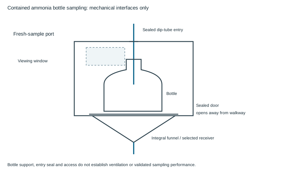
*Figure 14.6. The section identifies the sealed dip-tube entry, bottle support, viewing window, door and collection outlet. It represents the mechanical containment/access arrangement only. Ventilation and the selected receiving system require their own demonstrated basis.* [Structured enclosure roles](assets/C13/sample-enclosure.json).
Locate the sample connection and dip tube to limit stale inventory and sample loss; no allowable length is supplied here. The entry seal, tubing connector and bottle position must fit together so the sample does not miss the container or escape through the enclosure penetration.
For the selected bottle and handling task, size and orient the door away from the walkway in this arrangement.
The collection outlet needs an identified compatible closed receiver or another specifically accepted destination away from work areas. A funnel is not a disposal system, and an enclosure does not establish capture efficiency or ventilation adequacy. Keep bottle replacement, cleaning and component release under the adopted sampling and intervention procedure.
### Identify separation by the actual hardware and state
A removed or turned flanged spool leaves different fixed faces from a spectacle blank inserted between flanges. In the disconnected-spool comparison, the removable piece is out of the connecting position and the process-side opening has its selected blind flange. In the blanked comparison, the solid part of the spectacle device occupies the joint. The second is an installed closure. The first is a disconnection with a separately identified closure. The existence of either part on a drawing does not establish its actual separating state.
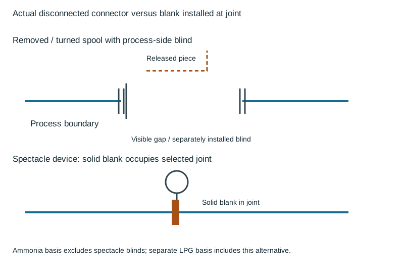
*Figure 14.7. The sketches identify the released connector, fixed joint faces and process-side blind flange, or the solid blank in the joint. They omit the connected injection system and its operating sequence.* [Structured closure alternatives and service eligibility](assets/C13/removable-closure-geometry.json).
The anhydrous-ammonia basis excludes spectacle blinds and retains a removed/turned-spool arrangement with a blind flange on the process-side connection. The separate LPG basis includes both turn-spool and spectacle-blank alternatives. For the selected hardware, keep that service distinction.
### Container orientation establishes the selected withdrawn phase
A small chlorine cylinder supplies gas in its intended upright position. A horizontal one-ton container has vertically aligned outlets at one end. The upper outlet serves gas withdrawal, and the lower outlet serves liquid.
For the connection drawing and actual installation, maintain the selected container orientation and outlet identity.
A generic container symbol with one unqualified line conceals that phase distinction.
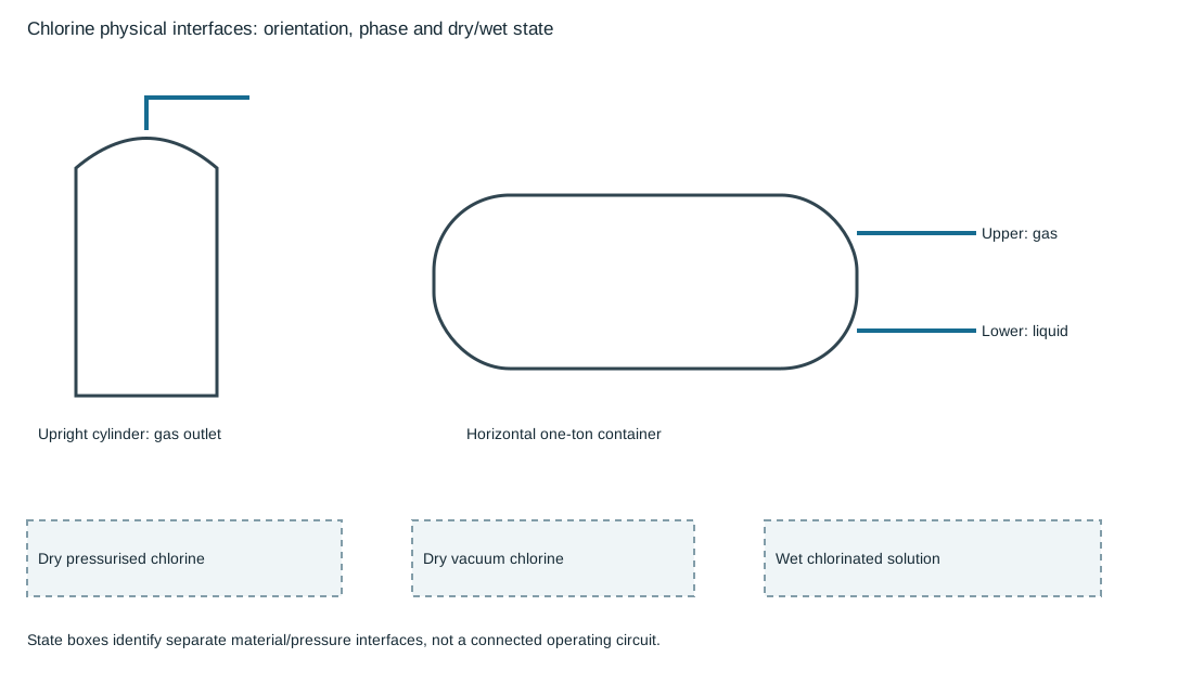
*Figure 14.8. The drawings retain gas versus liquid outlet identity and the dry pressurized, dry vacuum and wet-solution material interfaces. The dry-to-wet boundary is a separately evaluated equipment interface, not permission to connect the sketched regions directly. No water-eductor, operating-control or protective-check circuit is specified.* [Structured container and state interfaces](assets/C13/chlorine-physical-boundaries.json).
A container-mounted vacuum arrangement can reduce the length of pressurized chlorine piping. A separate pressure/vacuum arrangement retains a pressurized segment before the vacuum boundary.
For connection design, treat these as different physical assemblies with their actual detachable connections, support and moisture-exclusion needs.
Container changes expose the connection to atmospheric moisture, so capping unused pigtails and preserving the required dry condition remain part of the mechanical interface.
Dry chlorine piping and continuously wet chlorinated-solution piping need different material and joint evaluations. A material suitable for the wet receiving section does not become suitable for dry pressurized chlorine upstream.
For material and joint evaluation, keep the actual gas-to-solution interface, phase and pressure state visible.
The receiving destination and regulator vent termination require the selected package and facility basis. Conflicting vent-location details cannot be resolved by assuming one universally safe endpoint.
### Retain the chemical inventory basis before using an absorption quantity
A chlorine absorption reference pairs a chlorine inventory with either sodium hydroxide and water or sodium carbonate and water. The two alkalis are alternatives, not quantities to add together. Chemical identity, mass units and water-volume units must remain attached to every row.
| Chlorine inventory, lb net | NaOH, lb | Water with NaOH, gal | Na₂CO₃, lb | Water with Na₂CO₃, gal |
|---|---|---|---|---|
| 100 | 125 | 40 | 30 — unresolved use hold | 100 |
| 150 | 188 | 60 | 430 | 150 |
| 2000 | 2500 | 800 | 6000 | 2000 |
The literal 30-lb sodium-carbonate entry for 100 lb of chlorine is inconsistent with the inventory relationship in the 430-lb and 6000-lb rows. It is retained without a guessed correction. **Hold use of this table as an adopted absorption-sizing or preparation basis until its chemical/inventory quantities are validated.** Do not interpolate between its rows or infer a scaling rule that silently repairs the discrepancy. [Structured literal quantities and use hold](assets/C13/chlorine-absorption-inventory.json).
Even a validated alkali quantity would not complete an absorber design. Gas-loading rate, contacting arrangement, temperature rise, solution condition, receiving capacity and final collected-liquid disposition remain necessary inputs. A stock of alkali and water does not establish effective absorption of a release.
Keep the collected liquid out of unevaluated hydrocarbon-bearing drains.
# Chapter 15 — Insulation, tracing and thermal protection
Select insulation and tracing for the required duty: heat conservation, process-temperature stability, freeze protection, personnel protection, condensation control, acoustic attenuation or fire protection. Combined duties need a compatible assembly. Equipment that must dissipate heat can need a personnel shield instead of insulation.
Insulation delays cooling; it cannot indefinitely maintain a stagnant liquid above colder ambient temperature without heat supply. Include tracer supply, heated branches/dead legs, drainage or electrical controls, and the complete insulation/weather enclosure in the selection.
## Heat loss, moisture and inspection interfaces
Heat-loss, heat-gain and surface-temperature selections depend on pipe size, material properties, thickness, ambient temperature, wind and jacket emittance. Include flanges, valves, support attachments, nozzles and uninsulated connections. Contact tracing can overheat a sensitive product locally while a remote pocket remains cold; air or retained condensate can prevent uniform steam heating.
In cold service, preserve vapor-barrier continuity at joints, terminations, support penetrations and removable covers. Rain-shedding jacketing does not itself establish that barrier. Wet insulation changes thermal performance and can expose the pipe to corrosion. Select coating and inspection access with [corrosion-under-insulation conditions](#chapter-c15) in view.
## Duty and schedule selection
Specify the maintained temperature range, product overheating sensitivity, and startup, recovery, intermittent-operation and shutdown duties. A steam supply unavailable during shutdown cannot provide continuing freeze protection. Maintaining a warm line and reheating a cooled line can require different tracer capacity.
Use the selected method’s environmental conditions. One tracing basis requires lowest ambient temperature and highest wind speed with desired pipe temperature. Historical monthly-weather winterization criteria are a different basis. Select insulation type/thickness, tracer type/size/count, steam state or electric heater, and controls together. Greater steam pressure or closer contact can increase output and local overheating.
Drawings and schedules identify function, material, thickness, jacket and tracing. Apply each schedule’s temperature meaning, size row, band, notes and layer rules. NPS is not measured pipe OD. Do not interpolate a step, fill an unlisted row or choose an ambiguous boundary without a supported resolution.
### Cellular-glass cold insulation
The selected cellular-glass schedule limits condensation on aluminum jacketing at **80°F ambient, 80% relative humidity, 5 mph wind and 0.3 jacket emittance**. Its stated heat-gain bounds are 6.9–10.1 Btu/(h·ft²).
*Table 15.1. Conditional selections for nominal 6-inch pipe; hypothetical operating inputs avoid ambiguous band boundaries.*
| Operating temperature | Schedule band | Total thickness | Layer condition |
|---|---|---:|---|
| −40°F | −26 to −50°F | 3 in | Below−60°F double-layer rule does not apply |
| −100°F | −81 to −110°F | 4 in | Double layer; thicker layer inside |
Exact conversions are 76.2 and 101.6 mm; they do not specify metric products or authorize rounding down. Total thickness does not supply every product’s layer split.
A separate composite schedule puts polyisocyanurate inside and cellular glass outside; its larger listed component is cellular glass. Do not transfer its layer rule to the all-cellular-glass assembly.
Use the selected system’s sealing and jacket details. A polyurethane arrangement places its vapor barrier on the outside layer, seals overlaps with nonbreathing mastic and staggers insulation joints. Apply insulation to the prescribed clean, coated, dry, frost-free surface and preserve barrier continuity at interfaces.
### Polyurethane condensation schedule
The separate [polyurethane grid](assets/C14/c14-insulation-schedules.json) uses **80°F still air, 80% relative humidity and conductivity 0.15 Btu·in/(h·ft²·°F) at −50°F** to prevent condensation at the insulation surface. Bands run from ambient to 1°F, then 0 to −49°F, through −300 to −320°F. Rows include grouped 0.5–1.5-inch pipe, separate sizes from 2 through 30 inches and vessel/equipment; there is no 14-inch row.
For nominal 10-inch pipe, −125°F falls in the −100 to −149°F band and gives 3 inches. At −225°F, the −200 to −249°F band gives 3.5 inches. A 14-inch selection or temperature in a fractional gap between printed endpoints remains unresolved; agreement between adjacent rows does not supply a missing row.
These results do not replace the cellular-glass schedule’s different material, wind, emittance and heat-gain premises. Changes in climate, conductivity, outer surface or product require a supported evaluation. Preserve the selected vapor barrier, sealed overlaps, staggered joints, protected penetrations and dry/frost-free substrate.
### Carry size, material and fuel value through the complete economic lookup
The July 2012 revision-5 new-construction economic library provides fifteen fuel-value selections for each of calcium silicate, mineral wool and fiberglass. The values are USD 3.00–10.00 per million Btu at USD 0.50 increments. Its 45 pipe/equipment schedules and 45 separate tank schedules retain the stated conditions:
- 50°F ambient and 10-mph wind
- 15% return on capital after taxes
- 5% annual capital allowance for maintenance
- 7% annual energy-cost inflation
- Ten-year project life
These historical cost and financial premises do not establish a current investment evaluation.
Select the material and its compatible service range first. This library's maxima are 1200°F for calcium silicate, 900°F for mineral wool and 325°F for fiberglass. Then select the fuel-value schedule. Under this method, an input between two listed values uses the next higher value. Choose the actual printed pipe/equipment or tank row and its own temperature band.
Tank bands differ from the pipe/equipment bands and can also change with fuel value. For example, fiberglass tank schedules use different subdivisions within their 100–325°F range as fuel value changes. They cannot inherit one shared set of tank bands from the lowest-price table.
The [full economic schedule data](assets/C14/c14-insulation-schedules.json) and [guarded lookup method](assets/C14/c14-schedule-lookup.py) retain these selections as separate inputs. The method rejects an unlisted size, an uncovered temperature or a fuel value outside the supplied USD 3–10/MMBtu domain. It returns the selected band and all basis conditions with the thickness. No continuous thickness interpolation is supplied between fuel values or between printed temperature bands. An input in a gap between integer band endpoints needs an explicit adopted resolution. The retrieval method does not invent a rounding rule.
For a conditional example, assume calcium silicate on a nominal 10-inch pipe at 1050°F and a fuel value of USD 7.25/MMBtu. The next-higher rule selects the USD 7.50 schedule, whose 1000–1099°F band gives 7 inches. The same material's personnel-protection schedule gives 4.5 inches. If both duties and this compatible assembly are required, the 7-inch economic selection governs that local thickness comparison. Neither mineral wool nor fiberglass provides a material route for 1050°F in this library.
For NPS 6 calcium silicate at 550°F and an illustrative USD 3.25/MMBtu, the next-higher rule selects USD 3.50 and gives 3 inches in the 500–599°F band. USD 3.00 gives 2.5 inches; averaging to 2.75 inches violates this method. Mineral wool at USD 3.50 gives 2.5 inches; fiberglass cannot serve 550°F under its 325°F limit.
The calcium-silicate personnel schedule gives 2.0 inches for that NPS 6 and 550°F under 100°F still air and a 140°F surface target. Where this adopted assembly requires both duties, use the greater compatible thickness: 3 inches. Do not combine unrelated material or duty schedules. Provide corresponding layers, jacket, supports and clearance.
### Read normal and HOLD columns with their different temperature meanings
The independent August 2001 revision-10 library contains one personnel grid, two normal heat-conservation grids and two tracing/HOLD grids. Its economic basis retains:
- Average ambient −0.5°C (31°F) and average wind 10 km/h (6.2 mph)
- Ten-year plant/insulation life and zero tax
- USD 2.95/MMBtu fuel value
- 25% return and 80% boiler efficiency
It uses aluminum or stainless-steel jacketing. These results remain separate from the preceding 2012 fuel-value library.
For non-traced service in this route, normal upstream-equipment or line-designation operating temperature selects heat-conservation thickness. Startup, shutdown, steamout, upset and similar conditions are not used to establish that particular thickness under the stated method. Product/material suitability still considers the actual exposure states. For traced applications, HOLD or personnel-protection temperature selects the applicable thickness unless normal-operation heat conservation needs a greater value. Material type remains selected from normal operating temperature.
Where heat conservation and tracing/process stability apply together, compare the compatible normal-temperature and HOLD-temperature selections within this same basis. Process stability that needs a greater covering requires its actual calculation. Perlite uses the calcium-silicate normal/HOLD thickness schedules within this adopted route.
The normal mineral-fiber axis contains listed temperatures through 850°F, including a 550°F point. The calcium-silicate axis extends through 1200°F. The HOLD axes use 41, 60, 100, 150, 200, 300, 400, 500 and 550°F, with their printed Celsius pairs retained in the data. These are discrete listed-temperature columns, rather than the banded 2012 selections. No interpolation or next-higher-temperature rule is supplied here. A request between the listed columns therefore returns an unresolved lookup instead of silently applying the other library's rule.
For NPS 6 mineral wool, normal operation at 550°F gives 2.5 inches. HOLD at 100°F also gives 2.5 inches; HOLD at 150°F gives 3 inches and governs within this basis. [Structured example](assets/C14/c14-economic-methods.json).
For a conditional NPS 10 calcium-silicate comparison, normal operation at the listed 600°F column gives 2.5 inches. HOLD at the listed 150°F column gives 3 inches. The compatible HOLD requirement governs. In the mineral-fiber HOLD grid, NPS 20 at 200°F instead carries an asterisk requiring special design. That outcome must be resolved. It cannot enter a maximum-thickness calculation as zero, a missing ordinary number or permission to extrapolate from a neighboring size.
The mineral-fiber HOLD table's first row is printed “<1”, followed by NPS 1½. A separate NPS 1 row is not supplied there. The calcium-silicate HOLD grid includes both “<1” and NPS 1. Preserve that row distinction rather than borrowing the calcium-silicate row into mineral fiber.
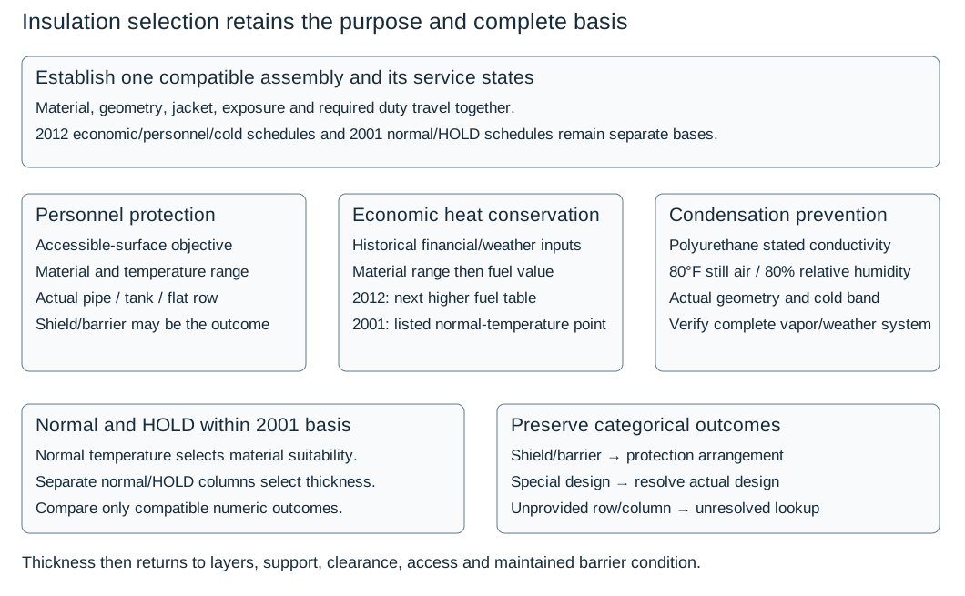
*Figure 15.1. A schedule lookup carries one basis, duty, material, geometry and temperature meaning into its outcome. The comparison of compatible normal and HOLD selections remains within the same assembly. Mechanical protection and special design are distinct actions, not thickness values. [Complete schedule library and applicability records](assets/C14/c14-insulation-schedules.json).*
## Materials, jackets and supports
Select products for normal and abnormal exposure, including steamout, cleaning and flushing. Adhesives, sealers and polymeric layers need suitability at their actual position and temperature. A cold composite’s polymeric layer is not automatically suitable at a hot pipe face.
At or below grade, a specified route uses cellular glass where ground moisture precludes wicking material; retain its temperature range and any thermal-shock cushion. Fibrous material can be unsuitable where a particular leaking product is likely to soak it. Insulation and insulating cement for stainless steel can require certification for stress-corrosion-promoting contaminants. Coatings, adhesives, mastics and sealants follow pipe material and temperature.
One jacket basis uses corrugated aluminum with a factory moisture barrier for ordinary duty and stainless steel for special protection. Another requires stainless steel in specified fireproofing, low-melting-alloy, critical-wiring and high-abuse applications, permitting aluminum elsewhere. Retain selected thickness, overlaps and fasteners. Hot sliding laps and cold sealed-barrier details are not interchangeable.
Insulation bands, rings, clips and studs hold the covering; [pipe supports](#chapter-c10) carry separate pipe/fluid loads. Continuous insulation at a support can require a specified load-bearing insulation and reinforcement system. Other hot-pipe details use shoes or local small-pipe cutbacks, with different heat-loss and corrosion interfaces.
Measure route clearance from the complete jacketed envelope, including acoustic layers and removable covers. Support and movement details accommodate pipe/equipment motion and insulation expansion, shrinkage or resilience without breaking cold vapor seals or displacing hot weather laps.
### Select securement for the layer and the diameter it actually surrounds
Wire and bands retain insulation or jacket. Their diameter input is not automatically nominal pipe size. A February 2001 revision-8 hot-pipe wire schedule uses **insulated outside diameter**. It applies to the inner layer or a single layer with insulation thickness below 3 inches. Its rows specify:
- 18-gauge wire below 12-inch insulated OD
- 16-gauge wire from 12 through 24 inches
- 0.020-inch-thick by 1/2-inch-wide bands over 24 inches for single and outer layers
Each row uses 9-inch spacing. Preserve the stated layer scope and diameter wording instead of treating this as a wire gauge selected from NPS. Wire-loop ends are twisted, bent over and pushed into the insulation to remove projections. Multiple layers are separately secured.
The [complete securement schedules](assets/C14/c14-construction-methods.json) also distinguish vessel orientation and temperature range. For the 70–600°F vessel method, vertical items use 12-inch band spacing and horizontal items 9-inch spacing. Band width is 1/2 inch for vessel OD 6 ft and below and 3/4 inch above 6 ft, with 0.020-inch thickness in either case. The 601–1200°F vessel method uses 9-inch spacing for both its inner and outer/single layers, with the same diameter-dependent widths and thickness.
Each layer is banded separately, tightened by a mechanical tool and secured with the specified stainless wing seals. Additional tightening by kinking is excluded in the higher-temperature route. These temperature-band methods do not establish a blanket insulation-material rating.
In the 70–600°F method, high-fire-risk installations whose covering serves as fireproofing hold both layers with 1/2-inch bands at 9-inch centers and exclude wire. That function-specific construction remains separate from an ordinary retention schedule. Anchor or bridle bands for head bands are 3/4 inch × 0.020 inch under the selected vessel methods. Where multiple bridle bands are used, head connections are staggered. These attachments carry the specified insulation/head arrangement, not the vessel contents or pipe weight.
The spring schedule adds movement take-up for bands on single/outer insulation layers and jacket weather finishes. It uses the vessel's **uninsulated OD**, temperature range, and a matched 4-inch Type 300-series stainless-steel spring assembly or an approved equivalent under that method. Its maximum initial applied extension is 1/2 inch per spring. Its count basis allows up to 2 inches of secondary extension after heating. More than one spring per band is equally spaced around the insulated item.
The initial extension and subsequent hot extension describe different states. The count is not a spring-rate, stress or fatigue calculation.
The [guarded securement method](assets/C14/c14-construction-lookup.py) preserves the complete printed count grid. Dashes and smaller diameters have the specific “no springs required” disposition in this route. They do not have a generic missing-data meaning imported from the electric HOLD matrix. The count grid's temperature rows are printed 600–800°F, 801–1000°F and 1000–1200°F, creating a shared 1000°F boundary. Its diameter bands likewise have explicitly printed endpoints, with a first isolated 2-ft-6-inch column and subsequent ranges beginning at 2-ft-7-inch, 3-ft-1-inch and other stated increments.
A value in a fractional gap or at the shared temperature boundary does not have a uniquely supplied lookup. Before application, resolve that exact boundary.
For a conditional example, assume uninsulated vessel OD of 12 ft and temperature 900°F. The 10-ft-1-inch to 15-ft band and 801–1000°F row give three springs per band. A 28-inch OD under the same temperature condition belongs to the smaller-diameter disposition, so this route requires none. The 12-ft result does not demonstrate that three arbitrary current springs can accommodate a vessel's actual movement. Match the specified component, preload, hot-extension basis, band/layer duty, actual temperatures and attachment before installation.
### Keep insulation support, jacket restraint and equipment support distinct
A vertical insulation course needs a load path to its selected collar, ring, clip or support angle. The weather jacket can need its own first-course support and a limit on accumulated motion. The pipe or vessel itself retains its separately designed structural support. A ring drawn around the covering therefore does not establish support for pressure contents or equipment weight.
One vertical hot-pipe collar detail applies to insulation at least 1-1/2 inches thick and vertical lines longer than 20 ft. It places the support at least 3 inches above the weld line and requires compatible metallurgy. Its insulation supports must **not be welded to alloy lines**. A separate skirt-supported vertical-vessel construction excludes stainless-steel vessels and uses compatible rods/nuts, bottom-head insulation securement, expansion material and a support for the jacket. It treats skirt-interior fireproofing only where the vessel drawings specify it. These are different equipment and attachment conditions, not a combined general welded collar.
The vertical-vessel clip/angle alternatives distinguish five functions. A segmented support angle carries an insulation course through its clips. A jacket-motion restraint adds a flat at selected elevations where shell expansion between supports approaches 1-1/2 inches. Under the local detail, it limits jacket travel to that amount. A first-course jacket support adds short peripheral angles.
A partial-fireproofing flashing detail is used where the covering stops below full vessel height and is **excluded on vessels subject to thermal expansion**. A thin-cover support applies where insulation is 1 inch thick.
The [structured A–E function and condition comparison](assets/C14/c14-construction-methods.json) preserves all eight associated construction notes. These include nozzle/weld clearances, clip/angle segmentation, skirt layer support, metallurgy and the diameter condition for top-ring banding slots.
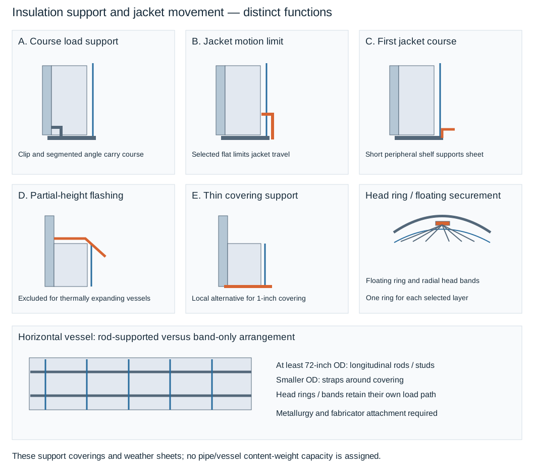
*Figure 15.2. A vertical section separates course support, jacket-motion limitation, first-course support, partial-height flashing and thin-cover support. A horizontal/head comparison separates a floating ring and head bands from a rod-supported shell arrangement. Profiles are schematic. The component table and condition record supply their own local dimensions without rating load or movement capacity. [Complete construction data](assets/C14/c14-construction-methods.json).*
A vertical-vessel head can use a floating ring for each insulation layer. Bands connect the head covering to the ring, with separate shell support angles. Its local normal-thermal construction places support angles at 12-ft-1-inch band-to-band spacing and packs the expansion joint with mineral wool compatible with operating temperature. A particular fireproofing-only detail omits those selected support angles and expansion joints. That omission belongs to this specific detail and duty. It does not authorize removing hardware from another qualified fire-protection assembly.
For a horizontal vessel at least 72 inches in OD, the selected arrangement uses compatible longitudinal rods supported by studs on both sides. It includes end circumferential rings and head floating rings. Band straps fasten to the longitudinal rods. The end head securement has its own ring/band path.
For smaller vessels, its alternative wraps bands around the insulation and does not require the longitudinal rods and circumferential support rings. Preserve the 72-inch threshold and actual metallurgy/fabricator attachment basis. Similar-looking rods or bands do not prove an authorized pressure-boundary intervention.
The local drawing uses 3/4-inch straps at 9-inch centers on the larger rod-supported arrangement. It uses 1/2-inch straps at 9-inch centers on the smaller alternative. These remain distinct from other vessel-orientation schedules.
### A weather boundary has to survive movement and removal
Hot-weather construction arranges overlaps to shed water and protects terminations around an exposed nozzle or manway. At an uninsulated penetration, metal flashing and its selected reinforced mastic join the jacket to the nozzle surface. At a head-to-shell junction:
- Where necessary, pack a void to establish a firm surface for the selected cover.
- Then form the standing seam or the specified lock-seam alternative.
These operations address the actual discontinuity. Adding a jacket without closing the penetration still leaves a path into the covering.
A vertical jacket uses the selected sliding laps, clips and expansion-joint arrangement. Its 2-inch minimum overlap and first-course support do not make the jacket a rigid tie between moving parts. The broader construction uses jacket fasteners on maximum 6-inch vertical-seam and 9-inch horizontal-seam centers where permitted. In cold service, screws and rivets are excluded on smooth or 3/16-inch-corrugated jacketing. For 1-1/4-inch-deep corrugation, the specified fastening exception places them on the high point.
A hot water-shedding lap is not a completed cold vapor seal. Preserve the actual material, fastening and sealed-barrier arrangement for the service.
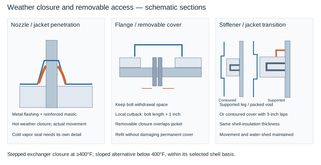
*Figure 15.3. The penetration inset separates flashing and mastic from the nozzle. The cover inset preserves a withdrawal space and removable closure. The stiffener inset distinguishes a supported, packed void from a contoured transition. The selected weather/movement detail is restored after removal. [Native construction conditions and tables](assets/C14/c14-construction-methods.json).*
For the selected hot valve/flange and tubular-exchanger details:
- Stop permanent insulation short of the flange by the bolt length plus 1 inch to allow removal.
- Retain the specified cover overlap on adjacent jacketed insulation.
This is a local withdrawal-space rule, not a universal minimum for every bolting arrangement. A removable valve enclosure retains its insulation rings, nonflammable high-temperature adhesive, fill insulation and flexible heat-resistant bonnet seal as applicable. Formed pipe/elbow covers and gore segments keep their water-shedding laps and staggered insulation joints. This particular drawing set does not supply a tee-cover specimen to copy.
For the tubular-exchanger closure, the stepped insulated end closure is preferred and required at shell temperatures of 400°F and higher. The sloped alternative is accepted below 400°F under that detail. Its channel and channel-cover insulation is installed only where specified. Preserve the local closure's mesh reinforcement, weather jacket and removable cover conditions rather than treating either drawn outline as a generic temperature rating. A manway-cover attachment that specifies studs installed before heat treatment cannot authorize field welding onto an existing vessel without its own qualified and authorized basis.
At a stiffener ring, one construction uses the vessel fabricator's insulation-support leg and fills the void behind the projecting ring. Another contours the covering around the ring and keeps the specified 3-inch laps above and below. Both retain shell-equivalent insulation thickness, securement and a water-shedding transition, but their physical support and void arrangements differ. After maintenance, restore the selected cover, seam, flashing, overlap and movement provision. Inspect dry material, accessible bolts and names/markings, coating repairs and sealed interfaces before concealment. A restored outline alone does not establish thermal, fire or corrosion performance.
### Removable-cover layer limits
Evaluate inner liner, intermediate insulation and outer fabric or metal face at their respective temperatures, including steamout or cleaning. Retain specified seams, fastening and removal arrangement.
One selected cover limits outer fabric to 500°F but requires a cold-face temperature of 110°F. The former is a material limit; the latter an accessible-face target. Neither permits that fabric to contact a hotter pipe. Use the selected heat-transfer assessment rather than assuming a linear temperature drop.
Layer changes must preserve packing-gland access, stud withdrawal, instrument clearance, drainage, leak observation and refitting. [Cover-function comparison](assets/C14/c14-cover-functions.json).
## Personnel protection without defeating the process or inspection
Personnel protection begins with accessible surface temperature and the operating or maintenance activity. A guard or shield keeps contact away from a hot item. Insulation changes heat transfer and its surface condition. The choice must protect the person while preserving the item's necessary heat rejection, bolting condition, operation and inspection access.
One adopted protection route applies to surfaces above 140°F reachable from normal work areas, walkways and platforms. Its stated limits are less than 7 ft overhead or less than 3 ft horizontally. It also applies to other readily touched surfaces. For new work between 140°F and 350°F it excludes ordinary personnel-protection insulation except specified high-alloy surfaces not susceptible to corrosion under insulation. Fabricated shields or an approved insulating-coating system are its alternatives. This is a local protection/corrosion choice, not a universal regulatory temperature or reach distance.
Above 350°F that route normally uses insulation. Flanges above 500°F use fabricated shields for personnel protection. Its hot-flange insulation restriction leaves bolts exposed to atmospheric cooling to reduce the potential for flange leakage. The thermal duty, flange bolting and contact-protection arrangements therefore have to be considered together. A removable cover does not automatically resolve an exception that requires exposed bolts at temperature.
The same basis treats normally cool lines that are heated during maintenance steamout differently. Their temporary protection can use restricted access, barriers, procedures and the prescribed work protection instead of permanently installing the normal-operation shield. That state is planned, not ignored because the normal fluid is cool. A separate equipment duty can require heat dissipation—for example from a condensate knockout drum—and use a guard or railing rather than thermal insulation. [Access and operating positions](#chapter-c04) and [maintenance work](#chapter-c19) connect these choices to actual exposure.
Removable protection is especially useful when access is frequent, but it must be inspectable and refittable. A cover that prevents packing adjustment or removal of studs has traded a maintenance function for an incomplete thermal one. Where leak monitoring requires periodic flange access, the selected removable arrangement should allow it without repeatedly damaging adjacent insulation. The accepted cover material, fasteners and sealing define what is restored after that work.
### Ventilated shield stand-off
Expanded or perforated metal permits ventilation, drainage, visual inspection and necessary heat rejection. The adopted shield method requires **at least 2.5 inches stand-off and calculation or testing to establish a maximum shield temperature of 140°F**. Longer pins can be needed. Preserve operating, inspection and removal space around valves, flanges and instruments. Attachment metallurgy and pressure-boundary work follow the qualified method below.
### A personnel schedule selects protection within its assembly
Personnel-protection thickness follows the surface-temperature objective and the selected material/construction. The July 2012 revision-5 schedule basis uses 100°F still air and a maximum accessible surface temperature of 140°F. It provides separate calcium-silicate and mineral-wool schedules for the printed pipe sizes from 1 through 30 inches, vessels and flat work, and storage tanks. The calcium-silicate pipe/equipment bands extend through 1100–1200°F. The mineral-wool bands stop at 800–900°F.
Their separate tank bands stop at 351–400°F. A vessel or flat-work row and a tank row are distinct geometric selections even when their listed thicknesses happen to agree.
The [complete personnel-protection schedules](assets/C14/c14-insulation-schedules.json) preserve each temperature band and row. A “mechanical shield or barrier” outcome for 350°F and below means that this protection route calls for that physical separation instead of an insulation thickness. It is not a zero-thickness thermal entry. This schedule also remains subject to the material/corrosion exception and protection arrangement described above. Finding a numeric cell does not remove the applicable restriction on insulating a reachable surface. The same assembly's heat-conservation requirement can govern where both duties are actually applicable.
For a conditional teaching lookup, assume a 10-inch nominal pipe at 550°F. The 500–599°F personnel band gives 2 inches of calcium silicate and 2 inches of mineral wool. At 300°F it instead returns the mechanical shield/barrier outcome. Thus a temperature change can change the protection mechanism, not only the purchased thickness.
At 1050°F the calcium-silicate pipe row lists 4.5 inches. The mineral-wool schedule supplies no such temperature branch. The absence cannot be filled by extending its final row or choosing a larger mineral-wool thickness by analogy.
A separate August 2001 revision-10 personnel basis uses an aluminum or stainless-steel jacket and a 60°C (140°F) maximum surface temperature. Its stated material maxima are 454°C (850°F) for mineral fiber and 649°C (1200°F) for calcium silicate. Its size/temperature grid includes NPS 1½ and 36 and flat work. Before reading that shared grid, select the material limit. The existence of a 1200°F column does not extend mineral fiber's 850°F material range. Its different exposure/reach and construction requirements remain its own basis.
The schedules provide conditional assembly selections. Verify the installed accessible surface, gaps, supports, jacket and maintained condition against the required protection duty.
### A shield needs attachment, safe edges and removable access
The July 2012 revision-5 shield method prefers flattened expanded metal because it preserves visibility, drainage, drying and air circulation. Perforated plate is an alternative subject to that method's approval route. The selected expanded-metal descriptions are 1/2-inch .051 style aluminum and 1/2-inch No. 18 style stainless steel. The perforated alternative uses 1/2-inch holes with 0.063-inch aluminum plate or 20-gauge stainless steel. Stainless shields are reserved particularly for corrosive atmospheres under this method.
Selecting an open sheet also retains the stated stand-off and the required thermal calculation or test. The openness of a shield does not establish its accessible-surface temperature.
For the pin-supported construction, the selected pins are 1/4 inch in diameter, at least 2.5 inches long and threaded at one end. Longer pins can be needed to achieve the 140°F shield-surface target. A stainless-steel nut spot-welded to a stainless disc connects the pin to the sheet support. The disc is 1-1/2 inches in diameter and 1/8 inch thick. A 1/8-inch hex-head stitching screw with an oversized washer secures the shield to the disc.
Complete coating after pin attachment where possible; otherwise repair every attachment before shield installation under the applicable coating system.
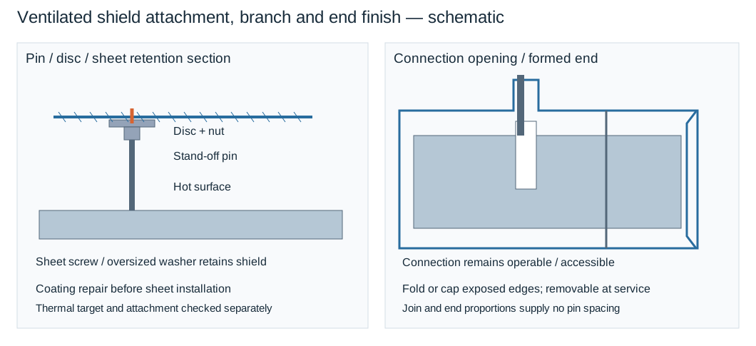
*Figure 15.4. The attachment section separates hot surface, stand-off pin, disc/nut and removable sheet fastener. The branch and end insets preserve an opening for connection access and a formed termination without an exposed sharp edge. Shapes are schematic. Pin soundness, spacing and surface temperature require their actual checks. [Structured construction conditions](assets/C14/c14-construction-methods.json).*
Approximate longitudinal pin spacing on pipe is 18–24 inches in this construction. For nominal pipe sizes up to and including 6 inches, it uses at least four circumferential pins equally spaced. Larger pipe uses approximately eight, with additional pins considered where support requires them. Other equipment needs adequate sheet support with spacing no greater than 24 inches in any direction. These are the local method's layout conditions, supplemented by additional supports as needed. They do not define a universal sheet-support capacity.
To terminate a pipe shield near a flange:
- Use its formed metal end cap.
- Secure the cap with an insulation band and stitching screws through band and cap.
Where an end cap is impractical, such as at a vessel, fold the sheet edge inward to avoid a sharp exposed edge. Branch openings and sheet joins must preserve ventilation, safe edges, operation and inspection. Flanges, valves and instruments needing service or removal use easily removable shields or barriers with sufficient stand-off for that access. For hot flanges above 500°F that remain uninsulated to preserve bolt cooling, use the specifically selected flange-shield arrangement. A generic close-fitting insulating cover changes that duty.
The attachment procedure remains separate from the sheet geometry. This method requires capacitor-discharge stud attachment to minimize heat input and penetration. Other arc processes need its explicit approved procedure.
For code piping/equipment, including items subject to postweld heat treatment, the selected capacitor-discharge procedure is qualified to ASME Section IX QW-192. Its stated route without subsequent PWHT remains conditional on that qualified procedure and authorized work basis, rather than a generic waiver. In-service and retrofit attachment also retain the required work authorization and in-service welding provisions.
Stainless pins apply to carbon-steel, low-alloy and stainless piping under this method. High-alloy piping requires its approved pin material. Confirm metallurgy, pressure-boundary intervention and coating restoration before attachment.
## Heating-jacket connections and drainage
A process-fluid heating jacket is a separate pressure-containing space around the core pipe; it can itself require insulation and weather jacketing. Under the selected metallic core-and-jacket method:
- **Liquid medium:** supply at the lowest inlet tapping and discharge at the highest point. Check intervening high points for retained gas and the annular path for bypassed heating surfaces.
- **Condensing vapor:** supply at the highest jacket tapping; drain condensate from the lowest pipe or fitting. A common return header is permitted. Provide effective noncondensable-gas clearing as well as liquid drainage.
The same basis requires countercurrent heating-medium/product flow. It recommends 1% installed slope and no more than eight jacketed pipe sections, valves or fittings per circuit. The count is not a length limit or capacity rating. A 1% slope over an illustrative 6.0 m horizontal run gives 0.060 m (60 mm) fall; fittings and return pressure can still prevent drainage. [Connection conditions and slope example](assets/C14/c14-heating-jacket-flow.json).
Changed medium, connections, return condition or jacket termination can change thermal duty. Retain [core/jacket mechanical interaction](#chapter-c09) and [separate test boundaries](#chapter-c18) as separate design checks.
## Steam-tracer type and service
Select tracer type with heat duty, product overheating sensitivity, steam condition, heated length and drainage. The insulation bore and fitting sections must enclose actual tube, connections and attachments.
Bare convection tracing can serve modest freeze-protection or maintenance duty when one circuit supplies enough heat. Isolated tracing reduces local contact heating for sensitive products, including specified aqueous chemicals, resins or amines. Compound-assisted tracing supplies higher heat density, more uniform heating or faster recovery where the product permits it. Multiple convection circuits add supply and trap assemblies; one suitable compound-assisted circuit can be preferable.
### Preserve the selected contact path during construction
Hold bare convection tubing against metal without compound. For isolated tracing, keep the specified isolating medium between tube and pipe when securing the tube.
Preinsulated tubing is another isolated arrangement: retain its insulation and secure it with high-temperature tape. Select delivery data for the actual contact construction, not tube OD alone.
For conductive tracing, compound creates a broader path from tracer to pipe. One detail spreads heat-transfer cement over a width of 2D to 3D, with D identified as the tracer diameter. Separate constructions retain cement and tube within a channel, or use preformed cement with a channel. Select the compound formulation and channel system for:
- Minimum and maximum normal and abnormal exposure temperatures
- Installation ambient
- Pipe/equipment size and configuration
- Required startup curing
- Solubility resistance and installed cost
Preserve the actual surface preparation, tube position, compound continuity and retention before insulation hides them.

*Figure 15.5. Six distinct contact constructions shown as schematic local sections: bare, spacer-isolated, conductive cement, cement/channel, preformed cement/channel and preinsulated isolated tube. Geometry and colors distinguish components. They supply no thermal-performance calculation or fabrication scale. [Selectable construction data](assets/C14/c14-tracer-construction.json).*
Securement belongs to each construction. The bare example uses stainless wire. The isolated and conductive examples use stainless bands and seals, with a stated band size of 1/2 inch × 0.020 inch. The preinsulated alternative uses high-temperature tape.
These contact details print a maximum interval of **15 inches (450 mm)**. That pair is retained as printed but is dimensionally inconsistent. 15 inches converts to 381 mm. Do not choose either value as a certified equivalent or repair it silently. Resolve the intended interval in the project detail before fabrication.
A separate straight-pipe banding arrangement specifies tie wires at **24 inches (600 mm)** centers. It cannot be combined with the contact-detail interval into one common spacing. The materials, detail and intended contact path determine which securement provision is applicable.
### Placement must agree with access and the thermal premise
Circumferential location affects contact, space within the insulation and the route past pipe supports. The illustrated convection arrangements distinguish horizontal and vertical pipe. For horizontal pipe, one tracer is displaced 30° from the bottom radial line. Two tracers are placed 30° to either side of that line. Three tracers use a bottom tracer with the other two 40° to either side. The three-tracer horizontal detail also calls for routing around pipe shoes.
For vertical pipe, the two-tracer illustration uses opposite sides and the three-tracer illustration uses three evenly distributed positions. Its two lower displayed radii are each 30° below the horizontal diameter. The one-tracer vertical view uses a displayed radius 30° from the downward page axis. This is a drawing reference, not a gravity-selected bottom sector of a vertical pipe.
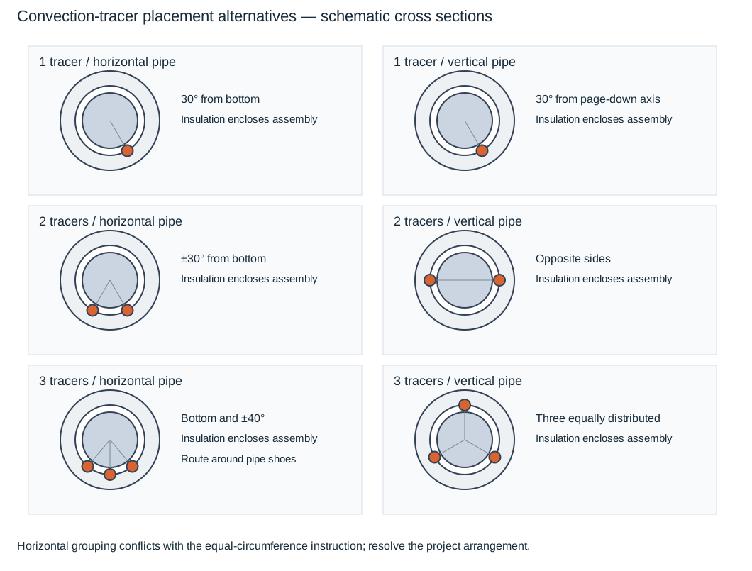
*Figure 15.6. Cross sections retain the particular one-, two- and three-tracer placement alternatives. Horizontal lower-sector grouping and vertical distribution are visibly different. Insulation surrounds the completed assembly; tube counts do not establish capacity. Angular references describe these illustrations only. [Placement data and constraints](assets/C14/c14-tracer-construction.json).*
This construction basis has two incompatible prescriptions for multiple tracers. The installation text requires equal spacing around the circumference. The illustrated arrangements group tracers in the lower sector on horizontal pipe. The latter does not satisfy the former for two or three horizontal tracers. Before installation:
- Keep the selected project arrangement explicit.
- Resolve that disagreement.
Do not rotate the illustration into an apparently reconciled detail or treat the illustrated angles as universal requirements. Retain the accessible surface, support avoidance, ease of connection and the actual insulation bore in that decision.
Tracers generally run parallel to and against the heated item under this basis, subject to the deliberately isolated contact construction. Moving a tube to clear a shoe can alter contact or create a rise. Reevaluate local heating and drainage as well as mechanical clearance. A convenient circumferential location does not prove heat delivery or protection against overheating.
Temperature control likewise has a defined objective. Pipe-wall or ambient sensing, self-acting control or another selected arrangement can serve intermittent operation, energy control, heat-up or shutdown freeze protection. An off/on steam control can be unsuitable for a particularly overheating-sensitive product. Sensor location and response must relate to the part of the system requiring control. A warm location does not establish that a cold dead leg is protected. [Sensing and control](#chapter-c22) supplies the measurement consequences.
For size and circuit selection:
- Establish nominal line size, required temperature, ambient and wind basis, insulation system and steam supply condition.
- Compare tracer type, tube size, number and heat-delivery data or the accepted calculation.
- Then verify maximum trapping length and accumulated rise, supply/return lead losses and trap/return conditions.
A circuit that has sufficient nominal heating output can still be too long or poorly drained to deliver it uniformly. Vendor data or a calculation is meaningful only with its applicable geometry and assumptions.
Define the lengths explicitly. The heated tracer length runs from its first contact with the heated line to its connection with the return lead. For a limit defined over the complete circuit, count its applicable supply and return leads as well as the heated length. Long lead runs can require separate pressure-loss evaluation. Do not compare the heated length alone with a limit whose scope includes those leads. The isometric should show manifolds, routing, traps, return and the circuit's identity so that construction and operation use the same configuration.
### Carry heat loss into a tracer-delivery comparison
A tracing selection has two different temperature differences. The product loses heat toward the ambient environment, while the steam supplies heat toward the product. Define the differences as follows:
$$
\Delta T_1=T_p-T_a,\qquad \Delta T_2=T_s-T_p,
$$
In these equations, $T_p$ is the fluid temperature to be maintained. $T_a$ is the selected ambient temperature, and $T_s$ is the steam temperature used by the heating method. In the customary-unit graphical method developed here, temperatures and their differences are in °F. With fixed steam and ambient temperatures, a higher maintained product temperature increases heat loss and reduces tracer delivery.
The method uses a two-panel chart. The first panel relates nominal pipe size and $\Delta T_1$ to heat loss per foot of pipe. The second compares that loss with delivery per foot from a specified tracer at $\Delta T_2$. Both ordinates are in Btu/(h·ft). For a straight parallel tracer serving the same heated run, a foot of tracer corresponds to a foot of pipe.
When comparing the ordinates, keep that length correspondence explicit. Extra tube length at fittings or another routing pattern does not automatically provide uniform extra delivery along the product line. Carrying one ordinate between panels compares quantities on the same heated-length basis. It does not make the two temperature differences interchangeable.
The available loss panel spans $\Delta T_1=0$–500°F and heat loss up to 400 Btu/(h·ft). The delivery panel spans $\Delta T_2=0$–350°F. Curves and examples are graphical selection aids, not a validated exact solver or permission to extrapolate beyond their ranges.
Its insulation assumption is 1 inch for nominal pipe sizes 4 inches and smaller, and 1½ inches for sizes 6 inches and larger. The chart does not assign the intervening 5-inch size to a thickness group. More fundamentally, it does not state the insulation material, conductivity or condition needed to transfer its loss curves to an actual installation. Thickness alone cannot establish that transfer.
Use the graphical values as a conditional teaching basis. A real selection needs a compatible thermal-property and installed-envelope basis, or another supported heat-loss calculation. Wet insulation, another material or a different jacket/ambient arrangement cannot simply inherit the plotted loss.
### Apply the wind correction to the loss, not to the steam temperature
The chart's loss basis is still air. Its listed winter-wind increments are:
*Table 15.2. Listed wind increments for the selected tracing-chart loss basis. [Structured wind table and method](assets/C14/c14-tracing-method.json).*
| Wind speed, mph | Increase in heat loss, % |
| --- | ---: |
| 5 | 7 |
| 10 | 9 |
| 15 | 11 |
| 20 | 12 |
| 25 | 13 |
| 30 | 14 |
For a listed increment $f_w$ expressed as a fraction, the corrected loss is:
$$
q_{L,w}=q_{L,0}(1+f_w),
$$
In this equation, $q_{L,0}$ is the still-air loss, and $q_{L,w}$ is the corrected loss. Both are in Btu/(h·ft). This modifies the quantity carried to the delivery panel. It does not change $\Delta T_2$, increase the steam temperature or create a heat-up allowance. The table does not define a rule for unlisted wind speeds or a universal correction independent of its thermal basis.
A graphical reading should retain its precision. If an approximate still-air loss is represented by a reading interval, apply the listed correction to both ends before comparing delivery. A candidate that clears only the lower end is unresolved against that interval. Selecting from an unrounded central estimate can conceal this distinction.
### Ordinary and compound-assisted delivery use different contact premises
The ordinary-tracer panel identifies outside-diameter tubing of 3/8, 1/2, 3/4 and 1 inch, together with two- and three-tracer 3/4-inch alternatives. It also has separate 3/8- and 1/2-inch curves for heat-transfer cement. The latter represent a changed heat-transfer path. They are not merely larger bare tubes or a multiplier that can be applied to every contact arrangement.
Where several ordinary tracers would be indicated, this selection route calls for considering a compound-assisted alternative, with 3/8- or 1/2-inch tubes recommended for that method. More area can use multiple tubes of those sizes. The actual product must still tolerate the local heat input.
The ordinary delivery panel prints an empirical customary-unit relation:
$$
q_T=h_c A'\Delta T_2,\qquad
h_c=0.4\left(\frac{\Delta T_2}{d_t}\right)^{0.25}.
$$
In these equations, $q_T$ is heat delivery per foot of tracer in Btu/(h·ft). $d_t$ is tracer outside diameter in inches. $A'$ is outside surface area per foot of tracer in ft²/ft. For a cylindrical tube, the geometric reconstruction is $A'=\pi d_t/12$. The coefficient 0.4 belongs to the stated customary-unit correlation, with $h_c$ expressed in Btu/(h·ft²·°F). It is not a dimensionless physical constant that can be reused unchanged with mm and °C.
This reconstruction verifies the printed ordinary-tracer arithmetic. It neither supplies the missing insulation properties nor derives the cement curves, contact resistance, installed capacity or a field acceptance margin.
The chart also lists tubing-to-pipe multipliers. These are 0.862, 0.878, 0.921 and 0.934 beside the respective 3/8-, 1/2-, 3/4- and 1-inch identities. Those printed mappings do not make nominal pipe size equal to tubing outside diameter or establish a general correction formula. Resolve the intended pipe alternative and dimensional basis before using it. The examples here remain explicitly outside-diameter tubing cases.
### Follow the indicated selection, then expose the unresolved conditions
A water-line teaching case uses nominal 4-inch pipe, fluid maintained at 35°F and ambient −10°F. Its loss difference is $35-(-10)=45$°F. With a stated steam temperature of 250°F, the delivery difference is $250-35=215$°F, and the graphical example indicates one 3/8-inch outside-diameter tracer. The associated printed steam premise is 30 psig at 250°F. That pressure/temperature pairing conflicts with the saturated-steam condition assumed for ordinary steam tracing.
Keep the temperature-difference arithmetic separate from an accepted steam state. Neither the calculated 215°F difference nor the indicated tube size repairs the premise. The same winterizing discussion elsewhere uses approximately 75°F as a water-maintenance objective. That is another stated duty, not the 35°F worked-case input.
A second case uses nominal 8-inch pipe, maintained fluid at 125°F, ambient 25°F, and stated steam at 150 psig/365°F. Thus $\Delta T_1=100$°F and $\Delta T_2=240$°F. The example indicates one 3/8-inch outside-diameter tracer on the still-air chart. Its plotted traverse is around 45 Btu/(h·ft). For the following sensitivity illustration, retain a deliberately broad approximate reading bracket of 40–50 Btu/(h·ft), rather than publish an exact recovered loss coefficient. This bracket is an authored graphical-reading allowance around the example, not a manufacturer's tolerance or a validated thermal uncertainty distribution.
At a listed wind speed of 15 mph, the 11% correction gives 44.4–55.5 Btu/(h·ft). At ΔT₂ = 240°F, the reconstructed ordinary 3/8-inch delivery is about 47.4 Btu/(h·ft), within that interval. It clears the lower end but not the upper. This information cannot confirm that candidate. The approximately 58.8 Btu/(h·ft) reconstruction for 1/2-inch tubing clears the illustrative upper end and is a candidate for further evaluation under the same compatible basis. It is not a final selection, because insulation applicability, actual steam condition and installed heat transfer remain to be established.
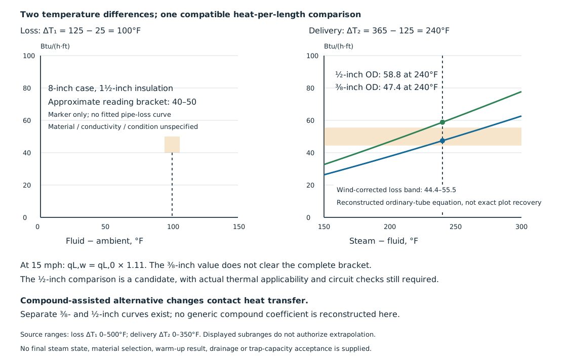
*Figure 15.7. A native example view preserves the two temperature differences and the approximate loss bracket for the 8-inch case. The delivery lines are reconstructed from the stated empirical ordinary-tube equation over the displayed subrange. They are not digitized exact source curves. The wind-corrected bracket makes the 3/8-inch comparison unresolved and identifies a 1/2-inch candidate without establishing a real installation. Missing insulation properties remain an applicability limit. [Structured method, raw conditions and calculations](assets/C14/c14-tracing-method.json).*
### Complete graphical alternatives and limits
The [complete curve companion](assets/C14/c14-full-tracing-chart.json) contains loss branches for nominal pipe sizes 1, 1½, 2, 3, 4, 6, 8, 10, 12, 14, 16, 18, 20 and 24 inches. Delivery alternatives are ordinary 3/8-, 1/2-, 3/4- and 1-inch OD tubing; separately plotted two-3/4-inch, two-1-inch and three-3/4-inch arrangements; and separate 3/8- and 1/2-inch compound-assisted traces.
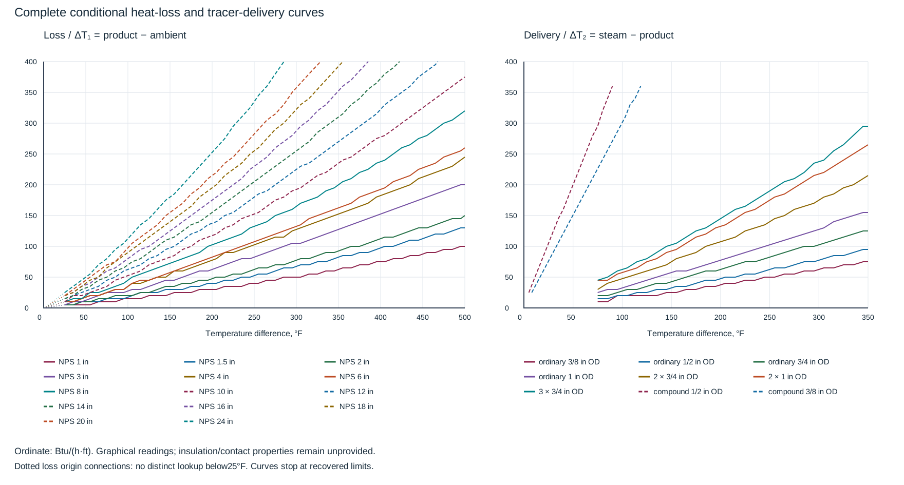
*Figure 15.8. Approximate graphical reconstruction. Loss: ΔT₁ 0–500°F; delivery: ΔT₂ 0–350°F; ordinate: 0–400 Btu/(h·ft). Each curve stops at its observed domain or frame intersection. Compound traces occupy only a small part of the delivery axis.*
Use these representation limits:
- Readings are rounded to 5 Btu/(h·ft). Working graphical allowances are ±5 Btu/(h·ft) for loss and ordinary delivery, and ±10 for compound and multiple-tracer branches. These are reading allowances, not manufacturing tolerances or installed accuracy.
- Loss and ordinary/multiple delivery are sampled at 10°F intervals; compound traces at 5°F. Display representatives preserve inspected monotonic shape within those allowances; raw rounded readings remain in the data.
- Separately recovered terminal readings reach the right axis, 400-Btu/(h·ft) ceiling or visible compound termination near 360 Btu/(h·ft). Upper-frame and compound terminal abscissas have a working ±3°F allowance. Do not continue curves across blank space.
- Closely merged loss traces have no distinct numerical lookup below 25°F; the zero origin is separate. A delivery/loss separation smaller than the graphical allowance cannot reliably distinguish candidates.
Read loss at ΔT₁, apply the listed wind increment, and compare the resulting range with the selected delivery branch at ΔT₂ on the same heated-length basis. Do not substitute arithmetic multiples for separately plotted multiple-tracer curves. The ordinary correlation does not derive compound contact performance. Recommended compound tubes are 3/8 and 1/2 inch under this method; multiple such tubes can add contact area, but lengths follow the selected manufacturer’s recommendation.
The loss basis remains 1-inch insulation for NPS 4 and smaller and 1½-inch insulation for NPS 6 and larger, with no NPS 5 assignment. Material, conductivity, emittance and condition are not provided. Compound formulation, contact coefficient and curing basis are also missing. Results are conditional comparisons, not installed ratings for another assembly.
The printed conversion is W/ft = Btu/(h·ft) × 0.293. Matched tube-to-pipe factors are 0.862 for 3/8-inch OD tubing to 3/8-inch pipe, 0.878 for 1/2 to 1/2, 0.921 for 3/4 to 3/4, and 0.934 for 1 to 1. Apply only those matched sizes on this graphical basis; they do not establish general interchangeability or compound equivalence.
At ΔT₂ = 200°F, neither compound trace provides a lookup, although the value is within the delivery-panel axis.
### Thermal indication does not finish the circuit selection
Under this particular route, ordinary tracer sizes range from 3/8 to 1 inch outside diameter. At 15–25 psig, its stated maximum lengths are 200 ft for 3/8- and 1/2-inch tubing and 300 ft for 3/4- and 1-inch tubing. At 50–200 psig, the small-tube limit remains 200 ft while the larger-tube limit is 400 ft.
Pressures above 25 and below 50 psig have no supplied length band. The 30-psig first example therefore cannot obtain a length permission from these rows. Values outside the stated bands remain unprovided. Compound-assisted lengths follow the selected manufacturer's recommendation instead of inheriting an ordinary-tube row.
These rows call the quantity tracer length but do not resolve the treatment of supply and return leads. Before comparing an actual circuit, establish that scope. Do not silently borrow the lead-counting definition of another procedure.
The same route defines pocket depth as an upward rise in the tracer’s flow direction. Total pocket depth is the sum of all such rises. It adopts a numerical maximum of 40% of the tracing steam gauge pressure expressed in feet. At 150 psig, this gives $0.40\times150=60$ ft.
A hypothetical route with upward rises of 18, 12 and 9 ft has 39 ft total. Intervening descents can make its net elevation change small without changing that total. It satisfies that isolated numerical comparison at 150 psig. It does not prove drainage, delivered pressure or trap capacity.
This empirical pocket rule is separate from another method's rise/pressure limits and from the 0.5 psi/ft trap-discharge lift allowance developed below. Do not merge their percentages or substitute net rise for a sum defined as accumulated rise.
### Count the upward route, including the local detours
Accumulated rise follows the tracer in its direction of flow. Count each transition from a local low point to the next high point. A later descent does not cancel the preceding rise.
At a flange the tracer's local detour can contribute several rises, identified here as A, B and C. At a valve, repeated wraps can contribute several occurrences of the same rise X. Along the overall route, rises associated with changes in the piping elevation and with local detours both belong to the count. The difference between the supply and termination elevations is therefore insufficient to describe accumulated rise.
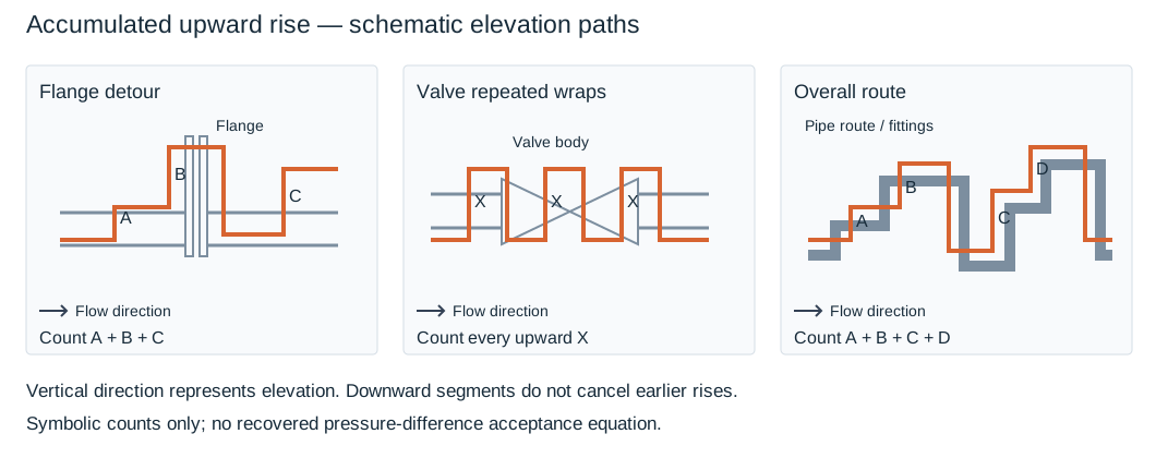
*Figure 15.9. Gray pipe, flange and valve outlines relate the orange tracer detours to the hardware in schematic elevation projections. Rise-counting paths identify flange contributions A+B+C, repeated valve contributions ΣX, and the route contributions A+B+C+D. The arrow follows the chosen flow direction. The vertical page direction represents elevation. These symbolic rises have no assumed dimensions. [Native counting data](assets/C14/c14-rise-counting.json).*
For any explicitly defined flow path with elevations z at its successive turning points, the counting operation is:
\[
H_{up}=\sum_i \max(0,z_{i+1}-z_i).
\]
Use one length unit throughout. Elevations in feet give accumulated rise in feet. Elevations in meters give meters. The expression only formalizes adding the identified upward segments. It supplies no pressure-to-rise conversion, rise allowance or drainage acceptance. Include all local high and low points rather than sampling the route so coarsely that a small flange or valve detour disappears.
Three separate numerical bases must remain distinct. The preceding empirical route uses 40% of tracing steam gauge pressure expressed numerically as feet. A separate installation clause limits accumulated vertical rise in feet to 15% of steam supply pressure unless otherwise approved. Its stated wording does not provide a general dimensionally derived pressure/height equation.
The accompanying pressure-difference display contains unresolved operator glyphs around its pressure difference and numerical factor. No scalar acceptance equation is reconstructed from that display. Neither the 40% route nor the 15% clause can be inserted into it as a repair. Establish the applicable resolved design criterion before accepting a circuit against a limit.
Check slope, tracer-inlet pressure, losses and condensate removal separately from accumulated rise. Recount after reversing flow or changing valve wraps and flange detours.
Bring the indicated tube/contact arrangement back to the actual pipe. Check the actual arrangement for:
- Overheated product near a contact tracer
- Cold branches and dead legs
- Sufficient envelope space and accessible joints
- Accumulated circuit loss
- All retained-liquid locations
This route uses insulation spacers where a contacting tracer could overheat specified chemical services. Spacers alter delivery as well as protection. A nominally adequate heat-per-foot comparison does not establish warm-up time, freedom from local overheating, or heat delivery along a long circuit after steam-pressure loss. [Steam and condensate service](#chapter-c12) supplies the trap inlet/return-pressure balance and condensate-removal duty. The following drainage account carries those conditions into the tracing route.
## Drainage, expansion and the trap discharge condition
Steam supply is selected to remain available during the required states and deliver the design load. A dry saturated supply and appropriately drained header/manifold support that condition. Each tracer's trap removes condensate and air so that heat transfer remains effective. A flooded or air-bound circuit cannot be repaired simply by increasing the insulation thickness.
Size the trap for both cold-start and steady condensate loads at the actual pressure differential; tube diameter or a single advertised capacity is insufficient.
Route supply and tracing from suitable high points downward where possible, avoiding pockets. A default steam-tracing method excludes spiral convection tracers because circumferential expansion can enlarge the gap from the pipe and horizontal pockets impair drainage. Doubling back also has pressure-drop and trapping consequences. Parallel, continuous circuits and their selected slope, branch and termination arrangement should preserve drainage while allowing access at supports and equipment.
Provide tracer movement, disconnection and weather-sealed penetrations using the following separate details.
### Movement, disconnection and penetration are separate interfaces
Under the selected bare-tracer construction basis, elbows and flanges absorb tube expansion where possible. Long straight runs instead use **12-inch (0.305-m) diameter horizontal loops at 60–100 ft (18–30 m) intervals**, preferably midway between fittings. These dimensions belong to that construction basis; assess actual tube flexibility separately.
The tube still needs its applicable material, pressure/temperature rating, bend radius and route evaluation. Its shaping method uses a mechanical tubing bender and rejects kinks, wrinkles and flattening. It typically uses bend radii of four to ten tube outside diameters, choosing the largest functional radius. A loop sketched without a kink does not prove that a particular formed tube meets those conditions.
The adopted text excludes unions from expansion loops. It separately calls for horizontal flange loops allowing shutdown drainage, with unions where needed to disconnect valves, pumps, tanks or other flange-connected equipment.
The associated expansion illustration depicts a union or elbow option within the expansion loop and therefore conflicts with that union exclusion. The native movement sketch below follows the union-free expansion premise and keeps the accessible removal union in its own panel. An elbow fitting alternative cannot be credited with removal access, flexibility or fatigue performance merely because an illustration offers it. Record a resolved construction choice rather than combining incompatible alternatives.
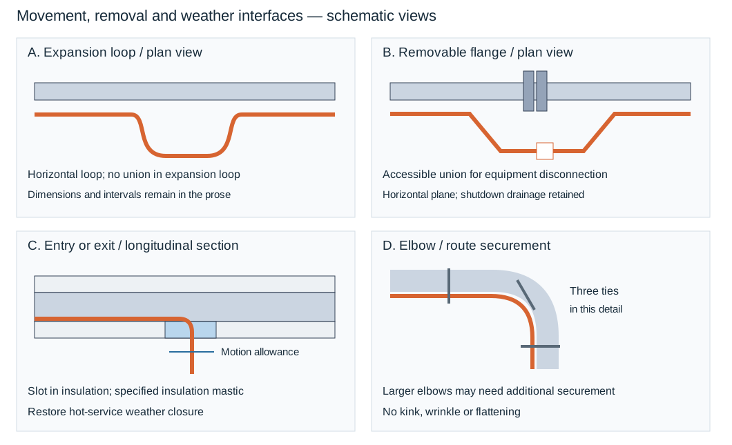
*Figure 15.10. The expansion panel is a union-free movement loop. The flange panel has a separate accessible removal union. The penetration panel shows a slot with insulation mastic, and the elbow panel shows securement maintaining the route. Views are schematic and the loop's plane is identified separately. Drawn proportions supply no dimensions. [Structured interface constraints](assets/C14/c14-tracer-construction.json).*
Form the tube to the union centerline without distortion or tension. To retain removal access:
- Place the removal joint where a maintainer can reach and disconnect it.
- Preserve the flange’s withdrawal space and the removable insulation interface.
The penetration construction shows the tracer carried outside the permanent insulation at the flange. It has insulation mastic at the openings and insulating tape around exposed tube. That arrangement preserves a separable tube connection. It does not justify leaving a hot exposed section unprotected or burying the union where removal damages the permanent covering. The alternative flange securement illustrations use wire or banding at the pipe and, in one arrangement, banding at the flange. Choose the complete compatible detail with its removal geometry.
At a straight-line entry or exit:
- Slot the insulation to accommodate tracer expansion.
- Fill the slot with the specified insulation mastic.
Select mastic, tape and jacket treatment for actual temperature, exposure and movement; preserve tube travel and restore weather closure after servicing. This hot-service slot is not a generic cold vapor seal.
At an elbow, securement follows the curved tube route. One elbow detail shows tie wires at three places, while the separate arrangement note allows additional wire or banding for larger pipe elbows. Neither establishes that every elbow requires exactly three ties regardless of size or curvature. Keep the tracer in its selected thermal relation to the pipe through the bend, with sufficient support and without pinching or flattening.
Under this basis, ordinary hangers, tees and elbows typically do not require extra tracer length. Valves and large equipment do. Supports or flanges in critical service require extra length. Insulated supports are considered for critical temperature maintenance. Carry any added length and local rerouting into the thermal and drainage evaluation rather than treating securement alone as proof of heating.
Each circuit has its specified separate trap station, with isolation and access for servicing. A continuing pipe run beyond the maximum trapping length requires another correctly supplied/trapped circuit rather than an arbitrary extension of the first. A branch, where permitted, needs its own trapping arrangement under that route. Traps and manifolds can also need freeze protection or drainage when shut off. Their operating heating and their shutdown condition are different states.
### Lift and backpressure can prevent heat delivery
A trap discharging to an overhead condensate return must overcome return-header pressure and the applicable lift. A particular tracing route prescribes a lift allowance of 0.5 psi per vertical foot. Using that adopted allowance:
\[
\Delta P_{lift}=0.5h,
\]
In this equation, **h** is upward discharge lift in feet, and **ΔP_lift** is the allowance in psi. This is the stated tracing-method allowance, not a universal density-based hydrostatic equation. The available differential also includes the actual pressure at the trap inlet, return pressure and applicable line losses. Gauge pressures can be subtracted when they share the same atmospheric reference. The pressure difference itself is not an absolute pressure.
For hypothetical h = 12 ft and return-header pressure of 8 psig, the allowance adds 6 psi. This gives a 14 psig backpressure estimate before additional discharge losses. If the actual trap-inlet condition is an assumed 22 psig, the remaining difference is 8 psi before those further losses. These figures explain the relation. They do not establish capacity or select a trap.
Its actual capacity and allowed backpressure must fit the operating, startup and shutdown conditions. The plant steam-header pressure alone is not necessarily the pressure reaching the trap.
A return connection and any required check valve follow the accepted discharge geometry and backflow protection. An accessible test point can help verify trap performance. [Steam and condensate systems](#chapter-c12) carries the broader supply, trap and return behavior. The tracing design retains the particular circuit and thermal duty. If changes increase lift, return pressure, heated length or lead loss, that connected selection must be reevaluated.
## Equipment, instruments and electric tracing
Include dead legs, covers, supports and large fittings where the selected critical-temperature method requires extra tracing. Equipment and pipe circuits can use separate supply/trap arrangements; added tube and lead lengths remain in the applicable trapping assessment.
### Cover the irregular surface without obstructing removal
A valve body, bonnet, pump housing or vessel head cannot be represented by the straight pipe's contact line alone. Hairpin tubing distributes contact over that surface while minimizing complete circles in the selected valve/pump method. Its tracer length per unit surface area is required to be at least the corresponding straight-pipe ratio under that basis. The number of hairpins is limited by the usable tube bend radius and accessible surface. Evaluate delivered heat and warm-up for that construction.
The selected valve/pump securement permits 1/2-inch × 0.020-inch (12-mm × 0.5-mm) stainless bands, high-temperature fiberglass tape or No. 16 gauge stainless wire unless otherwise specified. The irregular-surface cross section illustrates adjacent tubular tracers at approximately 3-inch spacing under insulation. That illustrative spacing is not an independent heat-output rule for every housing. To preserve and assess the construction:
- Preserve the contact type through the route, including the selected compound or deliberate isolating medium.
- Assess curvature, pressure/temperature suitability and exposed areas that the tubes cannot reach.
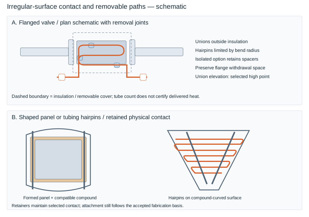
*Figure 15.11. A valve/hairpin removal panel in plan schematic shows unions outside the insulation and distinct isolated contact. An equipment panel compares a shaped heating panel with tubing hairpins on an irregular or compound-curved surface. Securement holds the intended contact arrangement while preserving service access. [Structured component and dimensional conditions](assets/C14/c14-equipment-instrument.json).*
The flanged-valve detail distinguishes small and large valves. For NPS 3 and smaller valves, it shows an isolated-tracing option with three insulating spacers. It says 3/8-inch tubing may be used for wrapping NPS 3 valves. The same detail's general bottom note specifies all tubing as 1/2-inch outside diameter. That exception/general-note conflict remains unresolved. Select and document the intended size rather than treating both as one certified instruction.
For NPS 4 and larger valves, the isolated arrangement calls for spacers at two-foot intervals along the tubing. For lines NPS 8 and larger, it calls for two tracers. The second goes around the end flanges and once around the bonnet on bonneted valves. Those additional routes remain subject to actual bend radius, contact, heating duty and removal geometry.
Place the valve's tubing unions outside the insulation and at the high point specified by that detail to reduce condensate accumulation there. This is a local removal/drainage construction and must remain consistent with the complete route. Locating one joint high does not demonstrate that all pockets are absent. A detachable valve or pump tracer connection differs from a dedicated expansion loop that excludes unions.
At a pump, the tube route follows the housing and removable flange connection while banding preserves contact. An elbow-fitting option shown at that connection is not equivalent to a separable union for maintenance. Establish the accessible disconnection actually needed by the assembly.
For vessels, the selected alternatives are prefabricated stainless heating panels formed to the required radius, or hairpin tubing panels. A prefabricated panel can use factory-applied nonhardening compound between its back and the vessel surface. For outside radii of curvature below 7 inches (178 mm), and for vessel bottoms with compound-curved surfaces, tubing hairpins can replace heating panels. Unless otherwise specified, those hairpins are embedded in heat-transfer compound. A rigid panel forced against an incompatible radius can lose the intended contact path. A fitted tube panel still needs its supported compound formulation and securement.
The horizontal-vessel construction illustrates 1/2-inch × 0.020-inch stainless bands and seals, with 24-inch (600-mm) spacing. Its flat-bar retainers are 1/2 inch × 1/4 inch with length as required. The vertical vessel view uses 3/8-inch threaded studs at approximately 24-inch (600-mm) centers with those bars. The cone-bottom arrangement instead calls for 1-1/2-inch × 1/4-inch flat bars, length as required.
Use each retainer with its specified construction, fabrication and material basis; pressure-boundary attachments require their applicable authorization.
Before concealment, check coverage, contact, tube bends and removal access. Reassess surface area, contact and clearances after valve or pump replacement.
### Keep the heated sensing path separate from the serviceable instrument
An instrument's process connection, impulse lead, sensing chamber and enclosure can have different thermal duties. Under the selected construction basis, direct tracing is confined to process-wetted parts and excludes electronic and pneumatic parts. Particular enclosures may instead receive indirect heat. A pressure-gauge enclosure receives process-line heat through conservation insulation carried to the enclosure or tracing continued to the gauge connection. A partially enclosed differential-pressure transmitter uses a steam heater block below it. The partially enclosed transmitter assembly has its own flexible insulation cover and clearance for transmitter removal.
A complete polyurethane enclosure can use the specified finned steam heater. Direct process tracing and enclosure heating remain separate selections.
For the selected gauge-glass and external-displacer applications, the tubing size is 1/2-inch (12-mm) outside diameter. Meter leads use 3/8-inch (10-mm) or 1/2-inch (12-mm) outside diameter. These printed pairs identify the particular application choices, not heat outputs or a common bore for every instrument. Determine the actual heat duty, pressure/temperature suitability, contact construction and removal path for the selected package. Preinsulated bundles are an alternative to field-traced and insulated leads where their supported thermal and installation properties fit the duty.
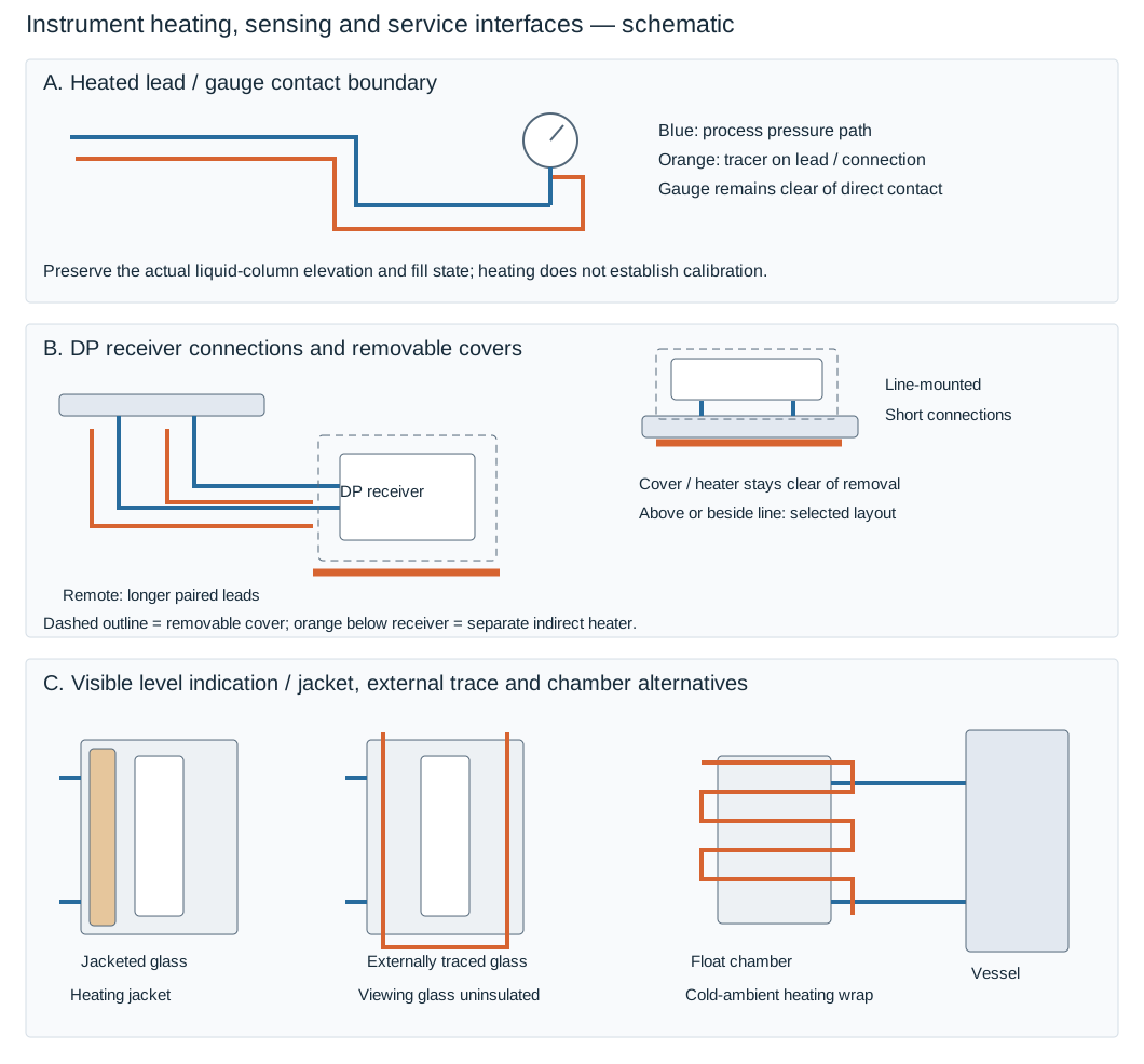
*Figure 15.12. Three schematic comparisons retain the physical interfaces. A heated gauge lead keeps the gauge clear of direct tracer contact. Remote and line-mounted differential-pressure sensing retain removable cover heating. Jacketed and externally traced level-glass alternatives preserve the viewing face, alongside the cold-ambient float-chamber wrap alternative. Blue paths carry process pressure, orange paths provide heating and dashed outlines identify removable covers. [Structured construction alternatives](assets/C14/c14-equipment-instrument.json).*
For a remote liquid pressure gauge, trace the lead and its connection while allowing the tracer to contact piping but not the gauge itself. The same contact boundary applies to the illustrated gauge or switch on a traced line. Horizontal and vertical main-line arrangements lead differently to the gauge connection. The liquid/steam pressure-transmitter arrangement can contain a hydrostatic leg between the tapping and transmitter. Preserve that actual elevation and liquid-column state when the thermal treatment is installed.
Remote differential-pressure construction traces and insulates the paired impulse leads together while providing the selected insulating cover around the receiver. Line-mounted alternatives shorten that connection and place the receiver directly by the sensing element, with distinct layouts above or beside the line. A flanged differential-pressure level transmitter and a differential-pressure vessel-level arrangement have their own process connections and removal joints.
Keep those interfaces serviceable. Under this basis, tubing unions and the heater/cover position must allow instrument removal without interrupting or removing the tracing. Retain lead density, zero/elevation offset and reference-path communication in the assessment. [Pressure-reference and level-calibration behavior](#chapter-c22) supplies the consequence of the actual fill, density and elevation state. Thermal construction must preserve that state rather than replace its calibration argument.
### Level-chamber heating and visibility
A jacketed level glass heats through its jacket; the externally traced alternative routes tubing around the assembly. For the illustrated traced detail, leave the viewing glass uninsulated and retain tubing unions for removal.
The external float-level chamber’s cold-ambient option wraps or coils tubing around the chamber. This equipment detail is separate from the default exclusion of spiral convection tracing on ordinary pipe. Preserve communicating process connections, fluid state, removal access and mechanical response; heating does not establish representative level or calibration.
Check gauge tracer clearance, glass visibility, cover refitting and instrument withdrawal space after servicing. Changed lead length, fill liquid, heater contact or enclosure can change heating and pressure/head interpretation.
Before insulating electric tracing, verify insulation type, bore and thickness against its layout. Protect heater and cold leads from mechanical damage. Do not embed cable in a seam or groove where the prescribed method identifies burnout risk.
### An electric-tracing HOLD thickness carries cable and environmental premises
HOLD temperature names the process condition to maintain. It is distinct from the normal operating temperature, the lowest ambient design temperature and the maximum permitted cable/sheath condition. A February 2001 revision-8 electric-tracing optimization basis supplies separate calcium-silicate and mineral-wool matrices. Their HOLD temperatures are 50, 75, 100, 125, 150, 175, 200, 225 and 250°F. Both use an assumed autoignition temperature of 500°F (260°C) and a minimum design temperature of −58°F (−50°C).
The calcium-silicate matrix identifies mineral-insulated cable heat-tracing sheath optimization explicitly. These numerical assumptions belong to that matrix basis. The 500°F value is not an established ignition temperature for every process fluid or an unrestricted operating limit for a cable.
The [complete electric HOLD matrices](assets/C14/c14-electric-envelope.json) retain all seventeen listed pipe-size rows, from 3/4 through 30 inches, and all nine HOLD columns for each material. Their dashes mean that no thickness selection is provided in that cell. They do not mean zero covering, permission to extrapolate the last numeric thickness, or that the line needs no heating. The [conditional retrieval method](assets/C14/c14-electric-lookup.py) requires the actual stated HOLD column and the retained environmental/ignition assumptions to agree before returning the stored outcome. It supplies no independently calculated cable-power or sheath-temperature result.
For a conditional comparison at NPS 8 and the listed 175°F HOLD temperature, the calcium-silicate matrix gives 3 inches. The mineral-wool matrix gives 2.5 inches. At NPS 30 and the listed 200°F HOLD temperature, calcium silicate gives a dash while mineral wool lists 4 inches. That distinction is visible data under the respective matrices. It does not establish mineral-wool suitability for an actual installation with a different cable, ignition premise or process duty.
A request for 180°F has no exact listed HOLD column, and a different minimum ambient cannot inherit these values without a supported evaluation. Retain material/product suitability at normal and abnormal exposure temperatures as well as the HOLD duty.
Insulation thickness can be increased when process reasons require it, or when justified for long-term economic and environmental carbon-dioxide-emission reasons under this route. Its general installation rule retains the greater of specified line-designation thickness and the applicable chart thickness. Tracing alone does not authorize changing a specified thickness unless the drawings identify that change. Establish the compatible requirement and actual heater/insulation assessment before applying such a comparison. Evaluate warm-up, local sheath temperature and installed protection separately.
### Distinguish the insulation bore from radial thickness and the finished envelope
A cable needs its selected contact, securement and installation space inside the insulation. An August 2001 revision-10 construction basis has a separate oversize provision for electrical tracing outside the steam/skin-effect provision. It uses these stated oversizes:
- 1/2-inch oversize for mineral fiber on NPS 8 and smaller
- No oversize for mineral fiber on NPS 10 and larger
- 1/2 inch for calcium silicate and perlite at all sizes
“None” is the table's oversize outcome. It does not prove that every cable fits beneath an ordinary nominal-size covering. The actual cable, product bore and permitted contact geometry remain necessary inputs. The separate steam/skin-effect provision uses 25 mm (1 inch), or 50 mm (2 inches) for dual-tube skin effect. Those different constructions do not select an electric-cable clearance.
Define the dimensions as follows:
- Dₚ is the actual pipe outside diameter.
- Dᵦ is the selected insulation bore.
- t is radial insulation thickness.
- j is the jacket’s effective radial contribution.
For a circular, concentric teaching geometry:
\[
D_{ins}=D_b+2t,\qquad D_{finished}=D_b+2t+2j.
\]
All terms use the same length unit. Dᵢₙₛ is the bare insulation outside diameter. Dfinished includes the selected jacket contribution. Actual jacket corrugation, overlaps, removable covers and fittings can add local projections beyond that idealized diameter. Cable placement can also produce eccentric or locally shaped construction, so neither a nominal bore nor this circular formula replaces the actual product envelope.
The dimensional example uses nominal NPS 6 with mineral-fiber insulation 3 inches thick and electric tracing. Its text calls the insulation ID “NPS 6 plus 1/2 inch”. Its drawing labels a “1/2-inch tracing gap” and a total OD of 13-5/8 inches. Those labels do not supply one consistent, certified radial/diametral convention.
Using an explicitly selected teaching pipe OD of 6.625 inches, a **0.5-inch diametral addition** gives Dᵦ = 7.125 inches and Dᵢₙₛ = 13.125 inches. A **0.5-inch radial gap** gives Dᵦ = 7.625 inches and Dᵢₙₛ = 13.625 inches, matching the drawing's stated total. Arithmetic explains that match. It does not establish that the radial interpretation overrides the text or that the drawn total includes a specified jacket thickness.

*Figure 15.13. Two conditional interpretations use the same selected 6.625-inch pipe OD and 3-inch radial insulation thickness. Their bore additions differ by convention. Jacket contribution j remains a separately specified input. Schematic cable position and circle proportions supply no clearance or thermal permission. [Inputs, raw construction outcomes and calculations](assets/C14/c14-electric-envelope.json).*
Resolve the selected product bore and intended oversize convention before ordering or assigning finished-envelope clearance. Preserve the drawing's 13-5/8-inch value as a stated example, rather than silently replacing it with the text-based 13-1/8-inch result. Neither value alone establishes the actual finished jacket OD. Before closure:
- Measure arrangement clearance from the complete selected envelope.
- Check the cable’s permitted temperature, contact and mechanical protection.
### Rigid-gap wind blocks and nonrigid reinforcement
A selected revision-2 rigid-insulation detail interrupts the annular axial air path with circumferential E-glass wind blocks at elbows, tees, flanges, skid/module boundaries and 20-linear-foot intervals on straight pipe. Its “1200°F E-glass” description is a local material condition, not a rating for every product, cable or assembly. Preserve cable space and contact without crushing or embedding it.
The corresponding nonrigid-covering detail adds an upper jacket lap from 9 o’clock to 3 o’clock to minimize compression by external pressure. It supplies no rated pressure, stiffness, deflection or verified thermal performance. This reinforcement does not replace a rigid-gap wind block.

*Figure 15.14. Alternative rigid and nonrigid constructions; schematic proportions. [Local conditions](assets/C14/c14-electric-envelope.json).*
Keep insulation dry and weather-protected during installation: under the specified electric-tracing method, the heater cannot dry wet insulation. Correct wet material, damaged sheath and incompatible insulation before concealment. Changed bore, blocking, compression or jacket condition requires reevaluation of heat duty and local cable temperature using the actual heater and insulation product basis.
## Acoustic and fire protection
Select acoustic covering for the required frequency-band reduction. Combined systems can put the acoustic layer outside the thermal layer. Retain specified densities, thicknesses, barriers, temperature protection, fasteners and openings. Noise-carrying metal supports/brackets can need treatment; resilient shoes or saddles must also meet [mechanical support duties](#chapter-c10). Removable blankets and covers must restore both acoustic and thermal functions after inspection.
### Compare the frequency bands that need reduction
The following example uses one adopted covering method. It uses fibrous glass at 6–8 lb/ft³ or mineral wool at 8–10 lb/ft³, with its specified aluminum or stainless jacket. The listed reduction depends on frequency and thickness. It is not a generic attenuation rate per inch or the sound-transmission rating of a separate barrier material.
*Table 15.3. Listed reductions for the selected covering. [Native frequency-band data and example](assets/C14/c14-acoustic-bands.json).*
| Frequency, Hz | 1-inch covering, dB | 2-inch covering, dB | 3-inch covering, dB |
| --- | --- | --- | --- |
| 125 | 0 | 0 | 0 |
| 250 | 0 | 0 | 1 |
| 500 | 3 | 5 | 8 |
| 1,000 | 12 | 14 | 16 |
| 2,000 | 21 | 23 | 25 |
| 4,000 | 30 | 32 | 34 |
| 8,000 | 35 | 35 | 35 |
Assume a teaching requirement of 8 dB reduction at 500 Hz. The selected 2-inch row supplies 5 dB, while the 3-inch row supplies 8 dB and meets that stated comparison under this covering basis. At 125 Hz all three listed thicknesses give zero reduction. Increasing thickness within these rows therefore does not solve that lower-frequency duty. Another noise-path mechanism or qualified construction is needed.
The assumed target is not an installed exposure limit or proof that a real covering achieves the listed result. Keep the specified material, density, jacket, openings, fastening and support interfaces with the assessment. Keep the comparison on its stated basis:
- Do not interpolate an acoustic value for a 2.5-inch thermal thickness.
- Do not add reductions at different frequencies to obtain a broadband result.
- Do not substitute a barrier’s STC value for this covering data.
After choosing a compatible acoustic/thermal system, recheck its complete envelope, route clearances, removable access and support transmission path.
### Fire-case credit follows the qualified assembly
One vessel-protection construction requires at least 4 inches (100 mm nominal in that specification) of calcium silicate in staggered double layers with stainless jacketing. It applies to its identified fireproofing duty. Wiring, actuators, low-melting-alloy equipment and other protected items have their own requirements.
That construction rule does not establish credit in a fire-case relief calculation. One specifically adopted route for insulation credited in an API 521 relief-load calculation requires testing and rating by the manufacturer or an approved independent agency. Its assembly must:
- Function effectively at a minimum 1660°F for at least two hours
- Retain the original shape and insulating value
- Retain most of the covering’s integrity
- Resist dislodgement by high-pressure firefighting streams
Under this same adopted fire-credit route, aluminum jacketing is excluded. Its selected jacket is at least 0.010 inch thick, with a smooth, annealed ASTM A240 Type 304 stainless-steel construction. Type 316 can be used where needed. Bands and other installation hardware are stainless steel to match the jacket material. These material and attachment conditions belong to this route, independently of the preceding four-inch construction example.
Use the qualified complete assembly. This route does not accept existing ordinary calcium-silicate or other insulation on resemblance alone; the exposure is a qualification requirement, not a universal material rating.
Keep the credited locations, installed system and qualification conditions in the relief/protection record and identifiable in the field. Removal, damage, replacement with another material or changed attachment can invalidate the assumed credit while leaving a visually covered surface. [The fire-case pressure basis](#chapter-c08), [external protection](#chapter-c15) and [recurring integrity](#chapter-c19) must refer to the same installed assembly and its maintained condition.
## Installation, inspection and changes
Store insulation dry and undamaged. Establish specified coating, clean/dry/frost-free substrate, tracer attachment and testing before closure. For the steam-tracing route that follows the process-line leak test:
1. Complete the process test and required coating; prepare pipe and tracer surfaces and install securement.
2. Blow supply and tracer runs clean before connecting trap assemblies.
3. Complete circuit connections and the specified steam-pressure leak test or appropriate hydrostatic test. Repair leaks and retest before concealment.
4. Apply and cure compound where required; protect exposed water-soluble compound from rain.
5. Inspect tracing, then install and inspect insulation and weather protection.
Another approved route retains its own sequence. [Testing and readiness](#chapter-c18) connects concealed work to the completed line.
Inspect layer staggering, joints, supports and barriers before covering them. Preserve stud withdrawal, packing adjustment, instrument access and removable-cover interfaces. A flange drain or telltale belongs only to its selected leak-detection detail; it is not a general permission to pierce a cold vapor barrier. Inspection ports and refitting seals must restore thermal, vapor/weather and acoustic functions.
Check completed jacket laps, penetrations, movement allowance and actual pipe-support contact. Changed covering thickness or support interfaces require affected [layout](#chapter-c04) and [movement](#chapter-c09) checks. Identify supply valve, heated circuit and trap consistently with drawings for isolation and maintenance.
Reassess changed valve surface area/removal geometry, tracer length/contact/trap load, return backpressure, broken barriers, and process temperature or overheating sensitivity. Restore the selected assembly and update [integrity](#chapter-c19), [modification](#chapter-c20) and [technical records](#chapter-c21).
# Chapter 16 — Coatings and corrosion management
Select external coating, galvanizing, internal lining and inhibition for their different threatened surfaces and degradation mechanisms. The same pipe can need several functions. External film adhesion/continuity, process-side chemical access and cathodic-protection current access require separate verification. [Material/allowance selection](#chapter-c02) establishes the containment basis; [condition assessment](#chapter-c19) establishes in-service damage evidence.
## Define the environment and the complete protection system
Atmospheric exposure, immersion, ground contact and the environment beneath insulation have different demands. Temperature affects application, cure and service compatibility. A pipe's normal temperature is not its only relevant condition. Intermittent operation, steamout, shutdown and nearby heat can also matter. The selected primer, intermediate and finish coats, lining or jacket-related protection must remain suitable for those conditions and for the substrate material.
A coating schedule connects those inputs with a complete system. Its preparation grade, profile, material combination, layer thicknesses, application conditions, overcoating interval, cure and examination belong together. A finish-coat name without the underlying preparation and primer does not define that system. Replacing a product or reducing a layer can alter intercoat adhesion, permeability, cure or mechanical response even if the finished color is unchanged.
Different items can have different exclusions. Nameplates, code markings, gasket faces, threads, weld preparations, approved factory-coated equipment and particular galvanized or nonferrous items may need protection from paint or follow a separate route. Some insulation weatherproofing is itself a specified surface system. Painting every accessible metal-looking surface can destroy identification or joint function while providing no demonstrated additional protection. [Joints and components](#chapter-c03) and [identification and records](#chapter-c21) retain those interfaces.
Buried selection adds soil moisture/resistivity, soil stress, contamination, potential biological attack, diameter, service temperature, field-joint method and inspection access. Shop application can improve control of substrate preparation, heating, application and testing. The installed result still depends on field-joint coating and handling. An excellent shop coating cannot compensate for an unprepared weld area or a damaged sleeve after lowering.
Service and lifecycle cost belong in the comparison. More elaborate application can be justified by inspection difficulty after burial or the consequence of a protection failure. A low-cost field wrap may impose temperature or cathodic-protection limitations. A thicker, tougher covering can resist handling damage while requiring a suitable adhesion and joint-restoration method.
## Establish the substrate before applying the film
Remove oil, grease, salts, dirt, spatter and loose rust by the selected substrate-compatible preparation. Salt washing and abrasive scale removal address different contaminants; blasting does not establish soluble-salt/oil removal or the required profile.
*Cleanliness grade* describes the prepared surface under its specified evaluation method. *Profile* describes the surface roughness needed by the coating system. Blast grades such as Sa 1, Sa 2, Sa 2½ and Sa 3 have different defined preparation conditions. The selected system determines the required grade.
Manufacturer-required profile is measured by its accepted method. More aggressive roughening is not automatically better. Roughening must remain suitable for the coating thickness and bond. It must not reduce the pipe below its required wall.
After grinding/dressing, verify remaining required metal wall and restore cleanliness/profile before coating. Film cannot repair structurally unacceptable pipe.
Stainless steel, galvanized steel and nonferrous metals have substrate-specific preparation. Abrasives and tools that leave iron or chloride contamination on stainless surfaces can defeat their intended condition. A galvanized surface can need removal of zinc salts, grease or a suitable pretreatment before painting. A process accepted for carbon steel is not automatically suitable for these substrates. Light abrasive preparation, washing, solvent or detergent methods are selected under the complete coating/material route.
Preparation has a time and environment condition. Prime before corrosion or recontamination reopens the surface. One painting route normally primes within four hours of blasting. Another specifies no more than eight hours after preparation and requires renewed blasting if rust develops earlier. These are locally specified windows, not a universal guarantee that an exposed surface remains acceptable for either duration. Observe the actual surface before the next layer and preserve its selected acceptance condition.
## Application, cure and thickness are controlled operations
Mixing ratio, allowable thinner, application method, mixing and application conditions, overcoating interval and drying/cure follow the material's instructions and the adopted specification. A coating that is dry to touch may not be fully cured or ready for handling or service. A compatible topcoat cannot restore a contaminated or improperly cured primer simply by covering it.
Surface temperature matters separately from air temperature. A particular new-equipment painting route requires the surface to be at least 3°C above surrounding-air dewpoint. Relative humidity must not exceed 85%. Its explicitly agreed local-condition provision provides the exception to those conditions. The same route has other temperature, weather, light and surface-moisture restrictions. An air thermometer alone cannot establish that a cold metal surface is free of condensation.
A separate blasting route requires the surface to be more than 3°C above dewpoint; do not replace its strict condition with the painting route's at-least condition.
Application method affects local coverage. Spray can coat large areas efficiently, but complex geometry can create overspray, dry spray, sags or poorly covered recesses. Brush application can work paint into corners, welds, edges and crevices. Roller application has its stated surface and priming limitations. Stripe coats address areas whose geometry tends to leave thin coverage. A visually coated edge does not establish the minimum film thickness there.
Wet-film observation during application and dry-film measurement afterward are different stages. The specified measuring technique, instrument, calibration and sampling pattern determine the result. Added compatible coats can repair inadequate thickness only after the required preparation and within the material's application/recoat method. Painting over rain, dust or condensation on an uncured coat requires its stated removal/recleaning disposition rather than assuming that a later coat seals the problem.
Welding and coating also have a sequence. For welding and coating:
- Keep specified weld preparations and future weld areas free of coating.
- Protect finished film from hot work.
A test basis can require uncoated welds until its pressure test, with a bounded primer exception. Another permits a painted spool only under its examination and non-sensitive-test conditions. [Joint formation](#chapter-c16), [construction](#chapter-c17) and [testing](#chapter-c18) establish which selected sequence is applicable. The resulting field-joint coating must restore the chosen system rather than merely match its color.
## Galvanizing and organic coating have different manufacturing routes
A galvanized surface uses a zinc coating with its specified substrate preparation, deposition, coverage and adherence. Hot-dip and mechanically deposited zinc have different processing applications. They are not interchangeable names for a painted zinc-rich film. The fabrication and coating method must suit the item's material, geometry and mechanical requirements.
For galvanizing, complete permitted welding first. After later damage or authorized hot work, use the specified repair. Zinc-coated high-strength bolts, nuts and washers require the applicable grade-specific route. A specification can require mechanical zinc coating for one group and exclude galvanizing for another. Thread clearance, retapping and subsequent assembly condition must agree with that route. Coating every high-strength fastener by the same process can change both its manufactured condition and its fit.
Galvanized acceptance covers coverage, adherence, thickness/weight, distortion and embrittlement; appearance alone is insufficient. Its permitted magnetic thickness or coating-weight method does not override an FBE method's magnetic-gauge exclusion.
Repair of damaged zinc coating follows a specified surface preparation and repair system, such as an applicable zinc solder, zinc-dust paint or sprayed-zinc method. A repair product's thickness and application requirements remain those of that method. Repair is an established protective condition, not proof that every repaired area has the identical manufacturing history of the original hot-dip layer.
Storage must avoid retained moisture and chemical contamination. Shipping treatment and later paint require compatibility with the actual zinc surface and selected pretreatment/primer.
## Buried pipe: coating continuity, adhesion and cathodic protection
A buried coating protects the pipe from an environment that is difficult to observe after installation. A *holiday* is a discontinuity through the coating to the metal detectable by the specified test method. Adhesion is the bond at the relevant interface. A coating can be continuous but poorly bonded, or bonded in most places while containing a local through-defect. Thickness, cure, continuity and adhesion therefore need separate evidence.
An adopted buried-steel route can require coating and cathodic protection together. Coatings can develop holidays during handling or later service. Impressed-current or sacrificial-anode protection then has its specified electrical and corrosion-control role. The coating material and its disbonded geometry can affect current access. Certain tape systems can shield cathodic-protection current, so dielectric strength alone is not the whole selection argument. The cathodic system, isolation interfaces and inspection remain suitable for the actual pipeline or plant-buried configuration in [buried piping](#chapter-c11).
Tape, extruded polymer, FBE and heat-shrink field-joint systems have different application and service behavior. A tape coating combines its selected mastic and backing over a prepared/primed surface. High service temperature or disbonding can limit its suitability. Heat-shrink sleeves use their selected backing and adhesive/mastic with controlled preparation and heating at field joints. Their application does not automatically restore another coating's full qualification.
A field-joint tape system requires its qualified preparation, pipe/tape temperatures and overlap onto sound shop coating. It is distinct from FBE pipe preheat/powder cure; cutbacks or heating conditions cannot be transferred between methods.
FBE is a thermally cured epoxy system whose powder identity, storage, substrate preparation, controlled heating and application determine the film produced. The manufacturer's application temperature and any post-cure are part of the method. Protect bore and bevels from contamination and retain the required cutback and transit protection. Powder batches and any permitted recovery/reuse remain traceable. Mixing brands or reclaiming material by an unqualified method changes the production basis.
Polyethylene and polypropylene systems can use two or three layers. In a three-layer arrangement, the prepared steel receives its primer. An adhesive connects the primer to the outer polymer coating. The outer layer provides its specified protection.
In a two-layer arrangement the adhesive can connect directly to the steel. Some naming conventions also call that layer primer. The label alone does not establish the number, materials or function of the actual layers.
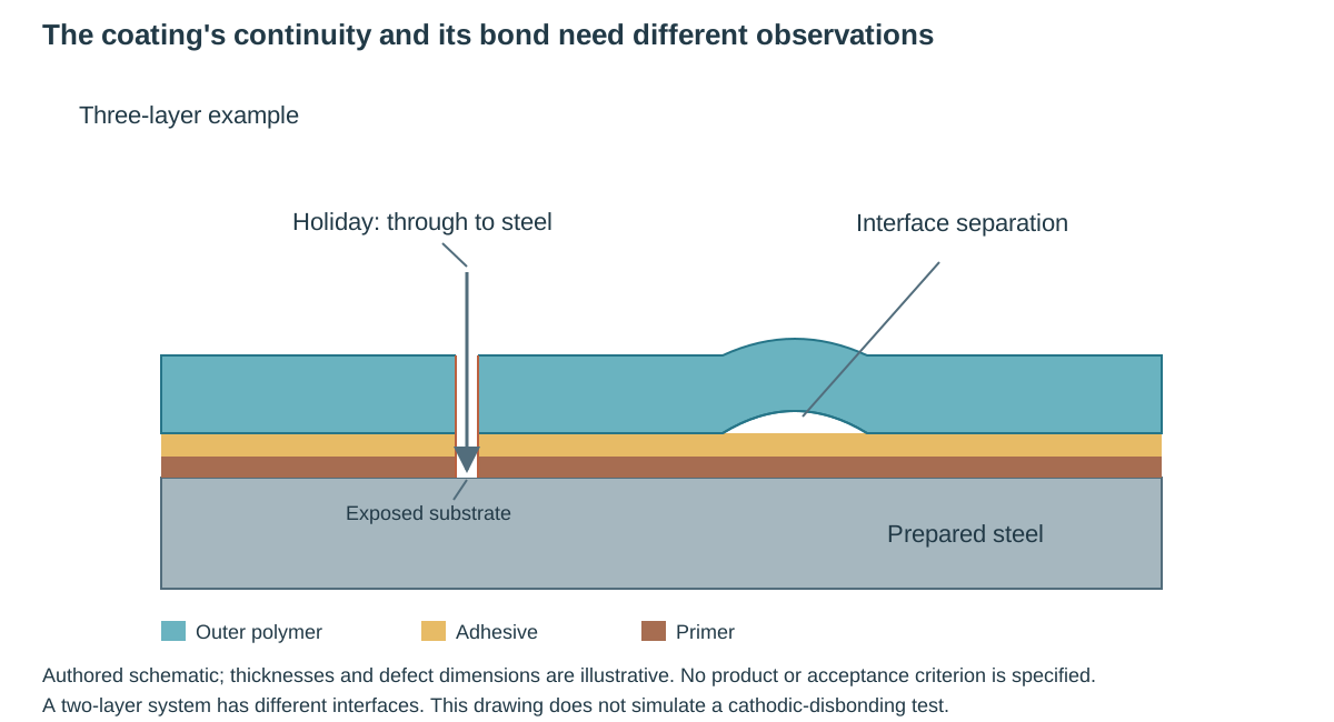
*Figure 16.1. Authored schematic of a three-layer example. A holiday reaches the substrate. An interface separation is a different defect. Layer thicknesses, defect dimensions and the particular materials are illustrative. The figure does not prescribe a product or acceptance level, and a two-layer system has a different arrangement. [Structured protection methods](assets/C15/c15-protection-methods.json) retain its condition distinctions.*
### Apply the complete qualified thickness schedule
One adopted external PE/PP system specifies the following minimum total thicknesses. They apply to that qualified system, including its layer and application requirements, rather than to every polymer-coated pipe.
*Table 16.1. Conditional PE and PP total coating thicknesses, with [structured schedule and conditions](assets/C15/c15-protection-tables.json).*
| Nominal diameter DN | PE total minimum, mm | PP total minimum, mm |
|---|---:|---:|
| ≤100 | 2.5 | 1.8 |
| >100 and ≤250 | 2.7 | 2.0 |
| >250 and <500 | 2.9 | 2.2 |
| ≥500 and <800 | 3.2 | 2.5 |
| ≥800 | 3.7 | 2.5 |
These totals do not supply primer/adhesive layer thicknesses, which follow the qualified application procedure. Lower PP thickness does not establish superiority to PE; temperature, adhesion, impact, indentation, aging and cathodic-disbonding conditions also govern.
## Qualification and production observations answer different questions
Coating-system qualification establishes the selected materials and application arrangement within its tested conditions. Applicator qualification establishes that the production method can deliver the required system. Production controls then establish the actual batch, surface, heating, interlayer timing and finished-film condition. Changing the system requires its specified requalification. One good qualification sample does not establish every production pipe.
Delivered coating evidence must identify the product, substrate condition and actual applied system. Items made during a process deviation require their specified disposition; a prior passing qualification does not release them. Coating must not hide dents, damaged bevels or unacceptable base material.
Finished-film observations include appearance, thickness, holidays, adhesion and cure. FBE qualification can use calorimetry for degree of cure and microscopy for voids or foaming. Knife or pull-off adhesion tests evaluate their specified interface and failure behavior. A cohesive failure within a sound film differs from adhesive separation at the steel, while a honeycomb void structure can have another unacceptable meaning. The test method and criterion determine the evaluation. “The coating was hard to lift” is not a complete report.
Mechanical and exposure tests add further questions. Impact and flexibility assess responses under their test conditions. PE and PP can have different impact temperatures, indentation limits and peel-resistance requirements. Thermal or ultraviolet aging assesses retained properties under its defined exposure. Cathodic-disbonding tests measure the extent of loss of bond under the specified imposed conditions and test temperature. A favorable result from one exposure cannot be substituted for another required one.
Holiday detection uses a coating-appropriate method, electrode, return/earth connection, voltage, coverage and surface condition. The test is checked by its specified calibration or known-defect procedure. Too casual a scan can miss a discontinuity. A universal high voltage is not a justified improvement.
The selected coating and thickness determine the method. A dry external surface is required by a specified high-voltage FBE route. Coating repaired after the initial scan receives its required reexamination.
Thickness methods are similarly specific. A stated FBE route requires calibrated eddy-current or electromagnetic techniques and excludes its named magnetic gauges. A galvanizing route permits its prescribed magnetic instrument or coating-weight method. The FBE production pattern can specify longitudinal positions and four circumferential locations, including a weld position on welded pipe. A convenient reading on a smooth patch does not establish that required coverage. Retain the actual method terminology, calibration and population rather than select an instrument by a generic “coating gauge” label.
### Rate the through-film and across-film observations separately
A cured FBE film can have a favorable outer appearance while containing voids or interfacial contamination. The selected microscopic route examines the cross-section and the coating–steel interface at 30–40×, using coating chips from test pipes where appropriate. Through-film means a section perpendicular to the pipe surface; across-film means a section parallel to it. The two directions are separate observations of the coating structure.
In the adopted finished-coating route the maximum degree is 2 in both directions. The associated production route also specifies maximum degree 2. Each direction must meet its own limit; do not average the grades. [Microscopic conditions and criteria](assets/C15/c15-fbe-foaming-planes.json). Report interface contamination separately; a favorable foam grade does not waive an unacceptable interface or establish degree of cure, adhesion, impact or holiday performance.
Retain separate grades and interface-contamination findings with sample/population identity. Failed specimens require the adopted suspect-population disposition; sampling damage requires qualified repair and reexamination.
### Select a holiday method from the actual coating and test stage
A holiday test observes a conductive path through an insulating coating to its metallic substrate. The instrument, electrode contact, earth connection, coating condition, coverage and voltage affect what that observation means. Excessive voltage can damage a film that was sound before testing. Insufficient or incomplete testing can miss a discontinuity. A dry high-voltage scan and a wet-sponge method are therefore selected parts of a coating procedure, not interchangeable ways to obtain the same certificate.
*Table 16.2. Three distinct adopted holiday-test bases, with [structured conditions and limitations](assets/C15/c15-coating-test-bases.json).*
| Bounded application | Test basis | Conditions that remain part of the method |
|---|---|---|
| Specified underground coating route before burial | DFT below 20 mils: low-voltage wet sponge; DFT at least 20 mils: high-voltage spark | Actual dry-film thickness selects the band; thin-film spark damage warning and complete coated pipe/joint/fitting examination remain |
| Specified FBE line coating | 2.2 kV at nominal 475 μm; 3.6 kV at nominal 725 μm | Direct earth on pipe, moisture-free surface, full coverage at no more than 0.3 m/s; voltage calibration at least twice per shift |
| Specified PE/PP line coating | 1 kV per 0.1 mm of coating, capped at 25 kV | Direct earth on pipe, dry surface, full coverage at no more than 0.3 m/s; voltage check at least once per shift |
Twenty mils is 0.508 mm, using 1 mil = 0.0254 mm. That route also contains a product/coat-count table assigning high-voltage testing to two-coat arrangements.
Its listed figures are maximum thicknesses. Its other coat-thickness notes do not guarantee a total of at least 20 mils. Retain this local inconsistency rather than infer actual DFT from coat count or invent a voltage setting.
The FBE settings and PE/PP per-thickness rule are separate test bases. Apply the PE/PP 25-kV cap even where its thickness calculation is higher; voltage alone proves neither coverage nor coating qualification.
### Retain temperature and deformation conditions in coating qualification
The selected FBE flexibility qualification requires continuity after its prescribed deformation: strain factor 0.02 at 0°C and 0.03 at 20°C, with any subsequent detected holiday constituting failure. Those laboratory results do not qualify the installed pipe's stress range or production bend; handling, bending and supports need their actual geometry/service assessment. The complete adopted test procedure controls specimen preparation, deformation and detection. [Qualification conditions](assets/C15/c15-flexibility-geometry.json).
PE/PP peel qualification also depends on operating band and test temperature. In the selected below-20°C operating band, testing at 23±2°C requires resistance greater than 35 N/10 mm for PE and greater than 150 N/10 mm for PP. Higher-temperature rows have different conditions; printed adjoining ranges do not justify invented endpoint assignments. Peel resistance is normalized force per strip width, distinct from polymer tensile strength or pull-off adhesion. Its adopted method must establish geometry, speed, temperature, mean force and trace uniformity: no section longer than 20 mm may be below 75% of the mean in the selected tensile-machine route. A favorable mean alone cannot establish that condition. [Scoped peel qualification data](assets/C15/c15-peel-geometry.json).
### Define the measured cure difference and disbond distance
In the discussed calorimetry methods, two scans of applied coating provide glass-transition temperatures $T_{g1}$ and $T_{g2}$. The measured difference is $\Delta T_g=T_{g2}-T_{g1}$, in °C as a temperature difference. It is related to cure. It is not a percentage conversion or proof of every coating property.
The specified FBE route uses a −2°C to +3°C range for this difference in both its finished-film and production-control requirements. The PE/PP FBE-primer route also uses that range. These are bounded cure criteria for the stated methods, not a general conversion of calorimetry into percent cure or installed coating life. Keep the adopted method and actual criterion with the result. The [structured test bases](assets/C15/c15-coating-test-bases.json) retain the quantity and scope.
Cathodic disbonding measures another response. The discussed methods impose a defined potential of −1500±10 mV relative to a saturated calomel electrode, in 3% sodium-chloride electrolyte, at their specified temperature and duration. They introduce a 6-mm-diameter coating defect and evaluate loss of bond after exposure. Their reported disbond radius is the arithmetic mean of four detachment distances measured **from the edge of the original defect**, not its center.
Temperature, duration, imposed potential and preparation remain part of the test. The FBE route distinguishes a 28-day qualification exposure from a 48-hour production test. The PE/PP route permits replacement of its 28-day test at 23±2°C for timely production intervention. The alternatives are a one-day test at 40±2°C or a two-day test at 65±2°C.
Replacement requires its approved comparison made during qualification on the same sample. This is an evidenced alternative test route, not a general acceleration law. A short hot test cannot be translated into long service life by an invented temperature/time multiplier.
## Repair and handling preserve the installed result
Repair must address substrate and all affected layers, prepare exposed material and sound surrounding edges, and restore compatible layer geometry, cure and examination. Filling a holiday or painting a blister without addressing surrounding adhesion leaves the defect mechanism in place. Repeated defects reopen application/qualification, rather than simply multiplying touch-up.
Transport, stacking, bending, field joining and lowering can damage a finished system. Use the prescribed padded contact and suitable handling slings. Abrasion, concentrated loads and thermal movement at storage supports matter, particularly where a coating softens in sunlight or has an ultraviolet-exposure limit. A repairable film is not a reason to accept avoidable mechanical damage as the construction method. [Fabrication and handling](#chapter-c17) carries these contact and preservation conditions into the work.
Before burial, inspect and repair at the specified stage. A holiday check immediately before lowering can detect transport damage. A permitted in-ditch check needs supports that protect the coating. Those supports are removed as specified before backfill. The ditch and backfill must not introduce sharp debris or contact that injures the coating. Field-joint continuity and actual inspection records should remain linked to the installed line, because later excavation or damage changes the condition established by the initial test.
Pressure testing and cleaning can also affect coating and lining. The medium, temperature, chemical residues and subsequent drying must be compatible with the actual protection. A coating that qualified for its service may not tolerate every acid-cleaning solution or hot-work temperature. [Cleaning, testing and readiness](#chapter-c18) establishes those temporary states, including which joints remain exposed and which repaired connections receive subsequent checks.
## Corrosion beneath insulation connects moisture, temperature and access
The insulation envelope changes exposure and visibility at the pipe surface. Water entering through a damaged jacket, support penetration or poorly restored cover can remain against the substrate and bring contaminants with it. Normal hot operation does not establish the condition during shutdown or intermittent service. The coating and insulation system must therefore be selected for the temperature/exposure history and remain inspectable where deterioration is consequential.
One adopted under-insulation piping basis specifies its selected carbon/low-alloy coating system for normal operation from 0°F through 350°F with intermittent operation up to 500°F. It selects another system for that same normal range when intermittent operation exceeds 500°F, and excludes coating for its continuous operation above 350°F. Its 300-series stainless piping rule selects a specified system from 0°F through 400°F, with an exception for material that has been stress relieved. Other high-alloy conditions require their own selection. These are bounded rules for that material and coating basis. The stress-relieved exception is not a general exemption for every stainless item that has received some heat treatment.
The actual coating composition, material, continuous/intermittent thermal history and exceptions travel together. Another insulation or service basis can have different criteria. Neither the temperature numbers nor the bare assertion “coat before insulating” defines a universal protection system. The selected coating must establish its intended condition at the substrate and remain suitable through the relevant states.
The corrosion concern can favor another personnel-protection arrangement. [Thermal protection](#chapter-c14) describes a local route using shields or a specified insulating-coating system for accessible surfaces in a defined moderate-temperature band instead of ordinary insulation, with its high-alloy exception. That choice preserves its contact-protection duty and the surface's corrosion/inspection condition. A shield is not a substitute for required heat conservation or cold-service vapor control.
Coating, vapor/weather details and inspection access act together. For openings in the envelope:
- Seal and restore openings by the selected material system.
- Retain drainage or telltales only where that detail provides them.
A cold vapor barrier cannot be punctured indiscriminately to imitate a hot-flange drain detail. When a cover is removed for inspection, establish the substrate/coating condition and restore the actual envelope. Operating checks and condition assessment in [inspection and maintenance](#chapter-c19) should be able to locate the protected surface and recognize loss of its required state.
### Keep system selection and product temperature limits together
The preceding under-insulation route has a consequential disagreement within its thermal selection basis. Its general piping rule permits the normal-range system for intermittent operation through 500°F. The detailed note for that system instead ends intermittent use at 450°F and directs 451°F through 1200°F to the high-temperature system. The high-temperature system's own use description begins at 501°F.
Those statements do not establish one consistent assignment through 451–500°F. They must remain unresolved for the selected route. This account demonstrates neither extension of the high-temperature description downward nor retention of the first system through that band.
Individual product limits add a separate constraint. The normal-range system lists one product with a 500°F maximum and another with a 450°F maximum. A system-level intermittent allowance therefore does not establish that every listed product can endure it. Conversely, a product's stated maximum does not independently qualify the complete primer/layer/application system or resolve the selection disagreement. Establish the actual coating composition, sustained and intermittent temperatures, exposure duration, substrate and qualified preparation/cure route together. The [structured thermal distinctions](assets/C15/c15-coating-test-bases.json) retain the local disagreement and separate product limits without creating a third selection rule.
[Thermal protection](#chapter-c14) provides the insulation/exposure interface but does not resolve this coating-route disagreement.
## Internal wet-sour-gas corrosion depends on water and flow
In wet sour gas, the metal's chemical environment is the water that actually contacts it, together with gas constituents, dissolved species, deposits and surface films. Similar bulk compositions can produce different corrosion behavior because flow transports water and solids differently. A bottom water pool, a moving slug and a dispersed film do not expose the circumference in the same way.
For the discussed wet-sour-gas comparison, define R as the molar CO₂/H₂S ratio on one stated composition basis. R is dimensionless. A ratio is not the concentration of either species by itself. The comparison uses R <20 for an H₂S-dominated domain, 20≤R≤500 for a mixed domain, and R >500 for a CO₂-dominated domain.
These domains organize the discussed mechanisms. They are not generic safe-service limits, corrosion-rate predictions or complete material qualification. The discussed iron-sulfide (FeS) and iron-carbonate (FeCO₃) scales have different protective behavior. Deposits, solids movement, chloride conditions, oxygen entry and elemental sulfur can disturb that protection or create local attack.
An inhibitor must reach the relevant water/metal interface, not merely appear in an injection inventory.
Stratified low-flow conditions can allow water and solids to settle. Deposits may block inhibitor access, absorb inhibitor or promote under-deposit attack. Solids that move along the bottom can also damage a protective scale. Slugging can change shear and film transport.
Dispersed flow can have a different scale/protection condition. A provisional superficial-gas-velocity value of 3 m/s in one wet-sour account is a practical proxy associated with solids transport. It is not the actual liquid velocity or a universal transition for every line. The source expressly anticipates a better criterion based on the relevant transport behavior.
Top- and bottom-of-line concerns differ. In a stratified CO₂ regime, continuously injected chemical in the bottom liquid may not reach the vapor-phase upper wall. Condensation there produces a corrosive water film. Selecting an inhibitor that partitions into the water phase can improve its bottom-interface delivery.
In a mixed or H₂S-dominated application, the relevant films and localized mechanisms need their own assessment. Changing external thermal conductivity can also change condensation behavior. An insulation or coating change can therefore reopen an internal-corrosion assumption.
The most useful treatment preserves the mechanism and observation separately. Field experience in a stated H₂S intermittent/slug regime found continuous inhibition ineffective, while some CO₂ inhibitors remained effective under relevant shear conditions. Proposed explanations involving bonding to sulfide scales or high-chloride well slugs remain hypotheses. They must not be presented as one established universal cause. The observed performance and the actual fluid/flow state govern the mitigation decision.
## Select mitigation for the surface it can protect
Continuous injection, batch treatment, pigging, condensation control, corrosion-resistant material, nonmetallic lining and corrosion allowance have different capabilities and consequences. Continuous injection can protect an accessible water-wetted surface if its chemical, partitioning, residual concentration and operating availability are adequate. Pigging can remove deposits or distribute inhibitor under its permitted configuration, but depends on piggability and the actual transported material. Batch treatment can renew a film under particular conditions while sending a concentrated chemical load to downstream equipment.
An allowance provides material available for deterioration. It does not suppress the corrosive environment. Severe localized attack can consume a small region rapidly even while the average wall remains satisfactory. An allowance used alone can therefore be inadequate under the discussed wet-sour localized mechanism. A corrosion-resistant alloy or lining changes the material/interface choice, with its own service compatibility, fabrication, inspection and repair constraints. [Material choice](#chapter-c02) and [lined fabrication](#chapter-c17) develop those consequences.
Select mitigation for actual water distribution and top/bottom interfaces, salinity, shear and solids competition. Verify injection and residuals against that delivery route; average gas rate or product name alone leaves these inputs unresolved.
Changes in the mitigation strategy require a corresponding observation and inspection plan. A higher dose is not automatically an effective remedy if transport to the surface is blocked. Reducing treatment because a prior inspection looked favorable requires the affected history and conditions, not an assumption that the mechanism has disappeared. [Operating integrity](#chapter-c19) carries those decisions into continued condition assessment without substituting a universal inspection interval.
## Startup, shut-in and intervention change the corrosion condition
Initial startup can produce solids, high salinity or lower pH, and conversion or release of mill scale can compete for inhibitor and burden downstream equipment. A program suited to stable production may not protect this state. Establish the starting contents, pressure, temperature and surface history, including whether the line contains sour gas, fuel gas or nitrogen. A selected enhanced program can use batching, adjusted injection and additional sampling under its identified class and conditions, with downstream chemical effects considered.
Shut-in duration and preservation matter. In the discussed prolonged fuel-gas-blanketed case, iron-sulfide scale can be replaced by iron carbonate with less protective behavior at restart. Opening to moist air can also alter the sulfide surface, with hydroxide formation and a changed sulfide condition when sour service resumes. The original protective surface cannot be assumed to survive those environments.
A line that has been depressurized, drained or chemically disturbed does not automatically retain the film represented by the earlier steady-state inspection. Planned short shut-ins, turnarounds, prolonged preservation, unplanned stoppage and abandonment therefore have separate source-defined strategies. Their time bands and treatment frequencies remain those of the selected mechanism and procedure.
Spent acid flowback is a concrete example. Lower pH, high chloride and fine solids can destabilize scales and degrade or absorb the chosen inhibitor. One wet-sour route excludes entry to the pipeline until **both pH ≥4 and chlorides ≤50,000 ppm** are achieved, using temporary separation and separate liquid disposal until then. Passing this screening does not establish ordinary steady-state protection. The admitted stream receives its required startup treatment and enhanced observations until stable production is established. The values belong to this route, not to every acid or pipeline service.
Hydrate-control chemicals can create a further corrosion interface. In the discussed sour systems, excessive methanol and oxygen brought with it can impair inhibitor/scale protection and promote elemental sulfur. The proposed influence on condensation and chemical protection is kept within that source context. Selecting hydrate control and corrosion control independently can miss this interaction. Changes in injection composition or rate need their connected fluid, flow and surface assessment.
Intervention also changes external protection. Hot work removes or damages film. Excavation changes its mechanical environment. Opening a line can alter internal scale and leave chemical residues. [Repair and modification](#chapter-c20) establishes the intervention and restoration route. Coating repair, inhibitor startup, cleaning and inspection then reestablish the affected protection state rather than relying on a certificate issued before the change.
## Verify the protection in service and preserve its basis
Monitoring must be capable of detecting the damage being controlled. A single-point coupon can miss isolated pitting elsewhere in a wet-sour line. Fluid sampling should include the relevant water, gas and condensate analyses and flow records. Injection records, consumption, inventory and residual measurements establish treatment availability and delivery. Each observation has a location, method and interpretation. A sample from an accessible point is not automatically representative of every water pool.
Sampling and inspection frequency respond to the mechanism, changing conditions and permissible deterioration. A source illustration uses a 10 mm/year corrosion rate and 5 mm remaining wall. It shows that an annual observation could arrive after severe loss. Its 1–4 week sampling discussion is tied to that high-chloride low-flow case and the permitted loss per event. Neither that frequency nor a simple thickness/rate division is a universal remaining-life or inspection method. Localized attack, uncertain rate, minimum required wall and treatment failures must remain part of the assessment.
The inspection plan verifies whether mitigation is effective, particularly after a strategy changes. External coating and cathodic observations, internal inspection and fluid/chemical monitoring retain their separate warrants. A sound surface patch cannot prove the whole coating bond. A satisfactory inhibitor residual does not prove that every threatened surface is reached. The observations are connected to the particular mechanism and configuration rather than collapsed into one “protected” status.
# Chapter 17 — Welding, heat treatment and examination
Welding changes the local material condition. Weld metal, adjoining heat-affected zone (HAZ) and unaffected parent material can have different composition and properties. The fusion boundary separates fused metal from adjoining material. Consumable selection, thermal treatment, hardness locations, examination and repair must address the actual region and process-exposed root. A satisfactory cap observation does not establish the HAZ or root condition.

*Figure 17.1. Authored schematic of a completed butt joint. Zone widths, reinforcement and measurement locations are illustrative. The figure identifies distinct regions. It is not a qualified weld preparation or a prescribed hardness survey.*
*The butt/cap and fillet/T-joint sections and location inset distinguish material regions, near-surface depth and HAZ fusion-line offsets. [Hardness-location interpretation](#c16-hardness-location-references) supplies their method context.*
## Establishing what is qualified
The Welding Procedure Specification (WPS) defines production instructions and permitted variables. The Procedure Qualification Record (PQR) records the qualification weld and its required tests; personnel performance qualification establishes capability within its own range. Procedure suitability and personnel capability are separate requirements.
The applicable construction code and adopted fabrication requirements determine the qualification route. ASME Section IX is a common qualification basis for pressure piping and related equipment, while the construction code and service specification add requirements for the finished item. Pipeline, tank and structural work can have different applicable routes. Historical references do not establish the edition or jurisdiction governing a new job. Establish that basis before applying qualification ranges.
Material, thickness, joint form, welding process, filler and shielding arrangements affect applicability. A qualification for one combination cannot be extended by resemblance alone. The WPS identifies essential variables, nonessential variables and supplementary essential variables where required by the qualification basis. A change that requires requalification is different from a change that requires revision of instructions within an existing qualification. Both changes need to reach production before work proceeds.
Supplementary tests can establish properties that a basic qualification does not address. Hardenable steels or a stress-corrosion-cracking service may require cross-sectional hardness traverses through weld metal, HAZ and parent metal. A notch-toughness requirement connects qualification and filler selection to the required test temperature. Duplex procedures may add corrosion, impact, ferrite and metallographic examinations. A qualified butt weld may still require a representative fillet, attachment or tube-to-tubesheet arrangement when the geometry or service creates another question.
A tube-to-tubesheet mock-up illustrates the purpose of this additional representation. Its production materials, thicknesses, joint preparation, access restrictions, bead placement, preheat, heat input and expansion method are reproduced as specified. Sectioning and targeted examination then assess the local joint that will actually be made. A conveniently accessible flat specimen would not establish the effect of a restricted production arrangement. The mock-up supplements the required procedure evidence rather than replacing the qualification route.
Postweld heat treatment also belongs in qualification. Test specimens required to represent the treated production condition receive the specified treatment. Repeated heat treatment can change material properties, so the qualification may need sufficient aggregate holding time for a further treatment after repair. For a procedure qualified to two treatments, this provision supports that stated accumulated cycle. It does not grant unlimited reheating. The production record preserves which cycles each joint actually received.
## Choosing and controlling the joining process
Process selection distinguishes covered-electrode SMAW, gas-protected GTAW/GMAW, externally gas-protected or self-shielded FCAW, and mechanized wire/flux SAW. GMAW transfer mode and the qualified equipment/program can constrain applicability.
Access and joint stage affect selection. A root made from one side has a different support and examination situation from a root that can be gouged to sound metal and welded from the other side. A process accepted for fill passes may be excluded from a single-sided root, socket joint or branch connection. A process restricted to a shop may be unsuitable at an exposed field location even if the material and thickness appear identical. The permitted position, equipment, consumable diameter and transfer mode must remain within the adopted procedure.
Transfer mode deserves particular attention in GMAW. Short-circuiting, spray, globular and pulsed modes must not be grouped under a single unrestricted permission. The procedure defines the electrical characteristics and the applications permitted for each mode. Modified-waveform or pulsed processes can also depend on the qualified equipment model and program. A replacement power source with a similar nameplate rating may not reproduce that qualified process. The production controls need the actual equipment and settings relevant to the qualification.
Consumables contribute composition and properties to the joint. The specified electrode or wire classification, flux combination, shielding gas and handling condition belong together. Some adopted procedures bind manufacturer and product identity as additional qualification variables. A neutral SAW flux with alloy wire is not interchangeable with deliberate alloy addition through another flux. An electrode suitable for a non-pressure attachment is not thereby suitable for a pressure-retaining joint. A general carbon-steel filler designation may not establish the required low-temperature toughness.
Hydrogen control also reaches the consumable and its storage. Low-hydrogen consumables, their drying and exposure controls, and the permitted root-pass exceptions follow the selected procedure. An exception for a cellulosic root or hot pass does not authorize its use throughout the joint or on another material group. FCAW diffusible-hydrogen classifications and material/service restrictions may differ between specifications. Selecting a wire because it can deposit metal rapidly does not resolve these qualifications.
Root protection is a separate interface with the process side of the joint. Back purge or other specified shielding must protect the region for the required passes or deposited thickness. Gas composition and the means of verifying its condition are part of the method, particularly for alloy and stainless joints. A substitute technique or flux-coated wire alone cannot satisfy an adopted procedure that requires purge. An alternative that permits welding without backing gas has its own qualified process, wire and shielding conditions. The alternatives cannot be assembled selectively into an unqualified hybrid.
## From prepared joint to completed weld
The prepared joint gives the process access to the intended fusion surfaces. Profile, root face, gap and alignment are checked before welding. Cutting oxides, cutting fluids, moisture, detrimental contamination and damaged bevels are removed by the applicable preparation method. A poorly fitted joint needs a controlled correction. Inserting extra metal or building up a bevel to hide an excessive gap is not equivalent to the specified preparation. Any permitted buttering, backing or consumable insert carries its own chemistry, fusion and examination conditions.
Incorporated tacks retain the finished joint's procedure, material, preheat and soundness requirements. Back-gouging, root, branch and attachment examinations need access before later passes or assembly conceal the required surface. [Fabrication and construction](#chapter-c17) establishes dimensional realization and work access.
Temporary attachments and accidental arc strikes also change pressure-boundary material. Removing a dog by hammering can leave a damaged area. Permitted removal and dressing must preserve the required wall and include the specified surface examination. Grinding an arc strike until its appearance disappears does not necessarily establish that the affected material or a crack has been removed. In a sour or cracking-sensitive application, the repair route can require etching, thickness measurement and surface examination, or removal of the affected pipe section. The criterion is the remaining material condition, not a neat surface alone.
Pipeline handling and alignment-clamp release must suit the incomplete joint and its prescribed welding sequence. Mainline release, incomplete-weld protection and reheating conditions belong to the selected pipeline method; see [pipeline construction](#chapter-c11).
### Join the online deposit to the surveyed run material
For an online attachment, the [selected temper-bead placement](#c20-temper-bead-placement) connects each deposit to a particular live run region. Its order, first-layer contact and final-pass location are part of the represented thermal method, together with actual wall, pressure, contents and cooling. A qualified scalar heat input cannot stand in for a changed contact geometry or an unexamined run-pipe toe. Through fit-up and production, preserve the selected attachment shape and bead-order instructions. A sleeve sequence does not establish a branch sequence by resemblance.
The [preweld coverage footprint](#c20-online-wall-coverage) likewise distinguishes thickness-location sampling from the full required defect/lamination examination region. Root and cap access, material-appropriate surface methods, hardness regions and delayed-cracking examinations then address the actual resulting weld at their specified stages. Relocating the branch after the survey, concealing a root before examination or changing the run's operating condition can invalidate the corresponding evidence. Retaining the original joint number on the final report does not prevent that loss.
### Carrying the drawing instruction through production
The [spool's weld symbol](#c17-weld-symbol-reading) must be decoded into a physical member, joint side, preparation and deposit extent before fit-up is released. Those drawing fields and the procedure address connected questions. A specified root opening must be achievable in the prepared joint. A member-specific bevel must be cut on the intended member.
A required opposite-side operation must remain accessible in the assembly sequence. A leg dimension, contour mark or all-around instruction describes the selected joint. It does not by itself demonstrate procedure qualification or establish the examination acceptance criteria.
[Thread sealing and selected short-root bridging](#c17-seal-bridge-root) add another concealment boundary. Proper engagement and dry makeup are established before covering exposed threads. Coverage of thread runout, fitting face and the specified bridge region is checked afterward. Keep the run-to-fitting attachment, the root sealing/bridge deposit and the valve's thermal exposure distinguishable in the work record. A continuous exterior deposit or a successful pressure test cannot recover evidence of a fit-up condition that was never checked. Additional bridge metal does not automatically establish full-strength or fatigue suitability.
## Thermal control has several purposes
*Preheat* establishes the required temperature of the joint region before and during welding. *Interpass temperature* describes its condition before a subsequent pass. The procedure can set a minimum, a maximum or both. Uniform heating and measurement at the specified locations matter. A hot spot near a torch does not show that the required material volume is at temperature. A satisfactory initial reading does not establish the condition several passes later.
The thermal cycle affects the weld and HAZ. In a hardenable ferritic material, the combination of local structure, hydrogen and welding stress can create a cracking condition. Preheat and controlled cooling are parts of its prevention, together with consumable and procedure controls. For stainless materials, excessive temperature exposure can create different metallurgical concerns. More preheat is therefore not an automatically conservative choice. The range is selected for the actual material, joint and required properties.
The procedure identifies the heating method, heated extent, means of measurement and necessary calibration. Gas rings, suitable torches, resistance or induction heating can have different applications. A method acceptable for preheat is not automatically an acceptable PWHT method. The record must be capable of showing the actual operation. This includes component identity, temperatures, timing, heating/cooling and any interruption that changes the intended cycle.
### Arc energy as a controlled production quantity
Amperage, voltage and travel speed are among the production variables recorded in welding procedures. Their relationship can be taught by separating electrical arc energy from the material's resulting thermal condition. For a steady illustrative pass, **V** is measured arc voltage in volts and **I** is current in amperes. Travel speed **v** is in millimeters per minute. The electrical energy per unit travel **E** is
\[
E=\frac{60VI}{1000v}\quad\text{kJ/mm}.
\]
The factor 60 converts the time basis from minutes to seconds. The factor 1000 converts joules to kilojoules. This expression assumes steady representative V and I. A waveform process may require the qualified method's measured energy rather than multiplication of simple averages.
Electrical energy per length is also not automatically net heat absorbed by the work. A thermal-efficiency factor requires a defined method and a supported factor. A procedure's term *heat input* must retain its actual measurement definition before the result is compared with its limit.
Current alone does not define energy per length. Material, thickness, waveform/transfer mode, pass arrangement, preheat and interpass conditions remain required alongside the procedure's measurement definition.
## Hydrogen bakeout and the prior-service condition
A new-material welding procedure cannot automatically be applied to metal that has acquired hydrogen in service. Wet H₂S, certain acid services and high-temperature hydrogen exposure can require a preweld bakeout under their defined conditions. The service history, material and exposure are therefore inputs to the weld route. A line name alone may omit the water, pH, concentration, temperature or hydrogen-partial-pressure condition that makes the requirement applicable.
The important mechanism is the combination of hydrogen, a susceptible local material condition, stress and temperature. In prior-service Cr-Mo equipment, welding directly on the base metal can create a hard HAZ and high welding residual stresses. If sufficient hydrogen remains and the joint subsequently reaches a susceptible temperature, hydrogen embrittlement cracking can occur. Bakeout aims to remove a contributing ingredient before the new weld is made. Hydrogen outgassing can also cause porosity in the weld pool. These mechanisms explain why a specified bakeout precedes cutting or welding rather than being treated as a later cosmetic repair.
Bakeout temperature and duration depend on the adopted material/service method and thickness. They cannot be transferred from a carbon-steel schedule to every alloy, or from an equipment procedure to an undefined line. The actual heated region and thermal record matter as well as a heater setting. The procedure may require cooling control between welding and PWHT. An unplanned loss of preheat needs its own disposition and any specified examination before work resumes.
Cladding and overlay complicate this route. If the welding thermal cycle reaches the ferritic base metal through a thin stainless layer, the base-metal HAZ remains part of the hydrogen-cracking question. If a sufficiently thick protected layer and a qualified method prevent formation of that HAZ, a specified exception may apply. Conversely, the stainless layer can prevent an effective bakeout of the relevant base-metal area unless it is removed by the adopted procedure. Under the discussed conditions, hydrogen removal from stainless cladding is much less effective than from ferritic steel. Thus, “heat the clad item longer” is not an established substitute for the required preparation.
The possibility of stress-related cracking beneath thick overlay is a separate, more uncertain question from formation of a hard base-metal HAZ. It should not be presented as an equally established reason to prescribe bakeout for every clad repair. The useful decision is to determine the actual substrate, prior service, overlay/cladding condition, anticipated heat penetration and applicable method. [Repair and modification](#chapter-c20) carries this distinction into the intervention plan and return to service.
## Postweld heat treatment and its sequence
PWHT is selected for the material, construction code and service. A service can require it where a basic thickness rule would not. Its procedure states the holding range and time, heating and cooling controls, heating arrangement, thermocouple locations and component support. The treatment has to reach the relevant metal. One favorable temperature trace at an unrepresentative location is insufficient evidence of a required through-thickness condition.
Furnace treatment can treat a complete assembly, while local resistance or induction treatment acts on a selected region. Each arrangement needs a suitable procedure. Local heating creates temperature differences along and around the pipe, and the heated extent, insulation and measurement locations become consequential. Direct flame impingement or an unqualified heating substitute can fail to provide the specified cycle. Lined or clad assemblies also have venting, differential material and protection considerations.
The interval between welding and PWHT is not governed by one universal sequence. A procedure for specified low-alloy materials may require maintaining preheat through PWHT. It can provide a separate hydrogen-removal and slow-cooling route when treatment must be delayed. Another adopted fabrication procedure permits slow cooling under an insulation blanket when immediate PWHT is unavailable. Those instructions belong to their full material and service basis. “Wrap the weld and treat it later” must not silently replace the first route.
Material transformation can require an intentional intermediate cooling step. For example, a particular 9Cr-1Mo route specifies cooling to 200°F (93°C approximately) before PWHT to complete its metallurgical transformation. This is a local material instruction, not loss of control or permission for other alloys to cool indiscriminately. The specified treatment record must show the actual sequence, not merely the final holding temperature.
Attachment welding, forming and dimensional correction also reach the treatment history. For a fabrication basis that prohibits further welding or forming after final PWHT, those operations precede it. An unplanned later operation requires a new accepted disposition. A repair that repeats PWHT must remain within the qualified aggregate thermal exposure and preserve the required strength, toughness and other material properties. Increasing holding time to obtain a lower hardness reading can create another unacceptable property change.
Final NDE and hardness testing are performed in the required treatment condition. Ferrite measurements can have a specified pre-PWHT timing even when final defect examinations are performed afterward. Thus “all examination after PWHT” is too broad. The joint record identifies the sequence and the result established at each stage. [Construction](#chapter-c17) uses this route to place attachments and permit access. The [system testing and readiness](#chapter-c18) account uses the released joint condition when defining the assembled boundary.
### Distinguish interruption from a planned delay
Loss of minimum preheat before a weld is complete changes the production state. The unfinished seam has experienced a cooling history different from the qualified sequence, and a later heater reading cannot establish whether cracking has already developed. One specified route for P-4, P-5A and P-5B low-alloy work requires magnetic-particle examination of the entire incomplete seam before welding resumes after such a failure. Resume only after the actual interruption, examination and permitted reheat disposition have been addressed. A convenient examination of the last visible bead is not the stated seam coverage.
That interruption is different from deliberately delaying PWHT after welding is complete. Under the same low-alloy route, intentional ambient cooling for more than a few hours requires a hydrogen-removal/slow-cooling stage.
Under this low-alloy route, if intentional ambient cooling will exceed a few hours, complete the following before removing preheat:
- Heat to at least 600°F.
- Then apply the specified 1-in insulation blanket over the greater of one pipe diameter or 6 in on both sides.
The method specifies no additional 600°F hold beyond the wrapping operation. Another adopted fabrication route supplies its own blanket-cooling and pre-resumption examination instructions. Neither is a general permission to substitute a blanket for the first route's hydrogen-removal stage or to improvise an unspecified alternative examination method. The distinct 9Cr-1Mo transformation cooling step above also retains its own purpose.
The work record therefore identifies when cooling began, whether the joint was complete, the affected material/seam, attained temperatures, duration and the examination/heat-treatment response. These inputs distinguish an interrupted weld, a deliberately delayed treatment and the designed metallurgical cooling step. They make a later decision inspectable without claiming that preheat alone proves freedom from cracking.
## Material and service variants
### Carbon and low-alloy steels
Carbon and low-alloy steels require their material grouping, actual condition and service to remain connected to the procedure. Low-hydrogen consumable control, preheat, delayed-treatment precautions, hardness and any required PWHT work together. Cr-Mo grades are not interchangeable merely because all are called low-alloy steel. The particular composition and original treatment affect the required production and examination route.
Sour and stress-corrosion-cracking services can add hardness or stress-control conditions. Caustic, amine, ammonia, acid and hydrogen applications have their own concentration, water and temperature definitions. Prior alkaline exposure can also require neutralization and cleaning before welding. A method appropriate to a specified alkaline residue must not be applied to every chemical residue without its material and contamination assessment. The service definition in [hazardous and sensitive services](#chapter-c13) supplies the local environment in which the joint will operate.
A test result outside a specified hardness limit requires a controlled correction and recheck. Removing and rewelding, or an accepted further heat treatment, may be alternatives. Their effect on properties and qualification differs. Repeatedly testing another spot until a favorable number appears does not establish the intended correction, and a hardness result cannot independently establish low-temperature toughness.
### Austenitic and stabilized stainless steels
Stainless procedures preserve cleanliness, filler composition, root protection and thermal exposure. Tools and abrasives used on other materials can leave detrimental deposits. Dedicated suitable equipment is required where specified. Low-carbon or specified dual-grade material reduces the carbide-precipitation concern in appropriate applications, but its name does not eliminate all temperature/service conditions. Generic ferritic-steel preheat and stress-relief rules must not be exported to austenitic stainless work.
Weld-deposit ferrite is another controlled property. The selected filler and procedure may target a Ferrite Number (FN) range, verified by a calibrated magnetic method at specified locations and stages. FN is an instrument-related scale used in the prescribed method, not a general volume percentage that can be substituted for microscopic ferrite measurements. Service temperature and stabilized filler grade can change the selected range. An average of six readings is meaningful only where that procedure defines the averaging method and sampling locations. An arbitrary handful of accessible points does not reproduce it.
Stabilized grades and heater tubes can require a further heat-treatment route tied to grade, consumable combination, wall and temperature. One stabilization basis addresses grades 321 and 347 base material welded with grade 347 root and fill consumables. Its prose requires treatment for wall below 1 inch (25 mm) when piping/equipment operating temperature, or the flame-side tube-metal temperature of a fired heater, exceeds 800°F (427°C). It separately excludes non-process-wetted welds.
Its schedule gives a 750°F (399°C) threshold for the corresponding thin-wall 347/347 combinations. These are piping/control-system roots made by GTAW or modified-wave short circuit, and fired-heater roots made by GTAW with back purge. The fill process is listed as unrestricted within that row. The schedule uses operating temperature for piping and tube-metal temperature for the heater.
For a process-wetted joint matching those material, thickness, consumable and process conditions, a relevant temperature above 750°F but not above 800°F lies in the interval where the two instructions diverge. That specific stabilization decision requires a disposition before release. Selecting 750°F as the apparently conservative value would silently change the prose condition. Selecting 800°F would silently exclude work covered by the schedule. This discrepancy does not erase the useful qualification, production and treatment method or stop unaffected work. It also does not turn fluid temperature into tube-metal temperature at a fired-heater surface.
### Choose austenitic treatment against both cracking and sensitization
Stress relief of 300-series austenitic stainless piping addresses a service question as well as a fabrication question. Reducing welding stresses can reduce a contributing factor in stress corrosion cracking (SCC), but the added thermal exposure can promote sensitization and susceptibility to intergranular attack. A treatment that helps one mechanism can worsen another. Neither a low-carbon designation, a stabilized grade nor a completed stress-relief cycle establishes immunity to SCC.
Actual grade/carbon specification, prior/proposed thermal history and both internal and external environments determine treatment selection.
One adopted method distinguishes unstabilized 304, 316 and 317 material whose carbon specification permits up to 0.08% from low-carbon grades limited to 0.03%. It discourages stress relief of those non-L grades because of sensitization. Where intergranular corrosion is the greater concern, including applicable acid services, that method instead favors low-carbon material without stress relief. Stabilized grades can serve different elevated-temperature duties, but their composition and treatment history still matter. The stabilization route described above and a casting's grade-specific solution treatment answer different questions from this stress-relief choice.
Internal SCC assessment includes actual aqueous chlorides, caustic concentration, operating temperature and a history of cracking. Low points and locations downstream of water injection can create a local environment different from the nominal main stream. Under the adopted method, known SCC environments above 140°F include aqueous streams with more than 50 ppm chlorides and streams with a cracking history. Its caustic provisions address all caustic services above 140°F and caustic concentrations above 30 wt% at temperatures above 110°F. These are conditions of that selection method, not universal onset temperatures or permission to ignore cracking below them.
The adopted instructions are not fully consistent at their operating-temperature boundaries. Their general large-pipe low-carbon/stabilized selection excludes services below 150°F, while the detailed internal-service selection uses 140°F. A matching service between these temperatures needs a disposition of the applicable selection basis. Choosing the lower number does not resolve the difference. The carbon and intergranular-attack exclusions must also remain attached to the service choice rather than being lost in a temperature shortcut.
External exposure is a separate input. Chlorides in air, wash water or insulation can reach the outside of a line whose process stream does not promote internal SCC. The detailed method considers service above 200°F with saltwater firewater or washdown, or a coastal location combined with personnel/plant-reliability consequences or difficult and expensive replacement. Its condensed selection route includes the coastal and consequence/replacement conditions but does not separately reproduce the saltwater branch.
Preserve that difference when selecting the applicable route. Qualified stress reduction can reduce susceptibility under the actual conditions. It does not eliminate every external cracking possibility. [Service and exposure assessment](#chapter-c13) retains the environment, shutdown and contamination conditions affecting the material.
High-pressure hydrogen adds a leak-consequence input under this method. Its prose identifies hydrogen partial pressure greater than 100 psia. The condensed route labels the threshold in psi and reaches the hydrogen question after earlier material, intergranular-attack and temperature questions. Retain the absolute partial-pressure reference and that branch qualification.
Do not replace it with total gauge pressure. Do not turn it into a universal hydrogen material envelope. Material qualification and the hydrogen service envelope remain with [the service assessment](#chapter-c13).
*Table 17.1. Different reasons for considering or opposing austenitic stress relief. The [structured treatment comparison](assets/C16/c16-austenitic-treatment-choice.json) retains the inputs, contrary cases and local method limits.*
| Assessment situation | Potential benefit or concern | Information that changes the choice |
|---|---|---|
| Low-carbon material in a defined internal SCC environment | Stress reduction can address a contributing factor | Actual aqueous chloride or caustic duty, temperature, cracking history, material and thermal history |
| Intergranular attack takes priority, or the specified material is susceptible to sensitization | Added thermal exposure can worsen the governing concern | Carbon/grade, acid or other relevant exposure and accumulated heat cycles; a no-stress-relief route can be appropriate under its method |
| External chloride exposure with consequential leakage or difficult replacement | Stress reduction is considered with the exposure and consequence basis | Washdown/firewater, insulation, coast, operating temperature, inspection access and replacement logistics; internal cleanliness alone is insufficient |
| Hydrogen service meeting the locally specified partial-pressure condition | Leak consequences contribute to selection | Absolute hydrogen partial pressure, actual material and preceding exclusions; no hydrogen qualification follows from treatment alone |
Once treatment is selected, specify its own fabrication cycle and covered joints. One adopted stainless stress-relief procedure uses 1550–1650°F. Its hold is 1 h per inch of nominal wall, with a minimum of 1 h. Cooling is in still air with the heat source removed. The cycle requires through-wall temperature and heating/cooling compliance within its grade/service basis. Under that method, selected treatment covers butt welds at NPS 2 and larger and all welds through the first block valve for piping below NPS 2. The separate small-pipe selection provisions retain their known chloride-cracking scope. Neither size nor a completed cycle removes the prior material/service decision.
Carry the resulting treatment or waiver basis into production, examination and later repair. A changed washdown practice, insulation condition, fluid chemistry or replacement grade can invalidate the assumptions used to select it. Preserve the actual grade, joints covered and accumulated thermal record so that later welding does not simply repeat a treatment whose original purpose no longer governs.
### Duplex stainless steels
Duplex joints require a material-specific route rather than a generic stainless permission. The thermal cycle and composition affect the phase condition and properties to be examined. Heat input, interpass temperature, filler and purge composition are therefore connected controls. Qualification can add toughness, corrosion and ferrite examinations and can restrict production thickness relative to its specimen. Dissimilar joints involving duplex retain the applicable duplex tests and the distinct requirements of the other material.
The following envelope illustrates a particular adopted duplex welding procedure for its specified product grades, including UNS S31803/S32205 wrought products in the required solution-treated condition. Its numbers and exclusions apply only with that complete material and qualification basis. They are not a general envelope for all duplex alloys.
*Table 17.2. Scoped duplex welding procedure conditions.*
| Controlled feature | Scoped duplex procedure condition |
|---|---|
| Nominal heat-input band stated by the procedure | 0.5–2.5 kJ/mm; the procedure also states 12.5–62.5 kJ/in |
| Maximum interpass temperature | 350°F (177°C) |
| Production addition of filler | Required, including specified tack and other production joints; autogenous welding excluded |
| Specified consumable family | E2209 for SMAW; ER2209 for GTAW/GMAW and SAW, with the specified duplex SAW flux |
| Excluded processes | PAW and FCAW |
| Additional procedure variables | Defined heat-input changes, interpass increase, consumable identity and purge composition require their specified qualification treatment |
| Qualification ferrite measurement | Weld deposit and HAZ examined by the specified microscopic method; 35–65 vol% under this basis |
The metric and inch energy bands are rounded statements of the same nominal envelope. They are not two independently exact thresholds to combine at a boundary. The applicable controlling units and measurement definition must be retained. The 35–65 vol% criterion is likewise distinct from the FN scale discussed for an austenitic weld. Corrosion or impact qualification tests are not replaced by a rapid screening test where the procedure expressly excludes that use. The production release depends on the qualified combination and required observations, not on heat input alone.
### Dissimilar joints, overlay and clad restoration
A dissimilar-metal weld has to join its materials while providing a deposit and transition suitable for their service. Filler selection can depend on temperature and chemical compatibility. The procedure may restrict the sequence of depositing a nickel alloy and stainless material. A consumable that can join the pieces mechanically is not necessarily compatible with the process exposure at the fusion boundary.
In a defined wet-H₂S service, an adopted restriction can exclude a full-penetration dissimilar weld whose fusion boundary is directly exposed to the process. The concern is hydrogen charging and cracking at that transition. A protected clad joint, socket joint or other specifically excepted configuration has a different exposure or leak-path situation. These exceptions must retain their geometric and service conditions. They do not create a general waiver for all dissimilar-metal welds in sour service.
Overlay and clad restoration combine a structural substrate with an alloy surface. Preparation strips the required clad material without reducing the base below its required thickness. It exposes and joins the base seam. Examination of that seam precedes concealment by alloy restoration.
The restored layer then needs its specified chemistry, undiluted depth, surface continuity, ferrite and bond condition. A thick-looking deposit can have excessive dilution or incomplete bond. A composition spot analysis does not establish both. If a repair penetrates into the substrate, restoring the structural section precedes the alloy repair under the selected method.
## What the examination establishes
An *indication* is an observation produced by an examination. Its evaluation determines whether it represents a relevant discontinuity and whether that discontinuity is acceptable under the selected criteria. Method, technique, coverage, stage and acceptance criterion are separate decisions. “NDE complete” is not a sufficient description of which part of a joint was observed or what the observation establishes.
*Table 17.3. Examination questions and evidential limits. The [structured examination tables](assets/C16/c16-examination-tables.json) retain these method roles.*
| Examination or test | Main question answered | Consequential limitation or companion check |
|---|---|---|
| Visual examination | Is the accessible preparation, surface, profile or completed arrangement consistent with its criteria? | Concealed root or internal geometry requires access or an accepted remote method |
| Radiographic examination (RT) | What relevant internal indications appear in the radiographic image of the examined volume? | Geometry and image quality govern useful coverage; an image does not establish chemistry or every crack orientation |
| Ultrasonic examination (UT) | What indications are obtained with the qualified sound path and technique? | Access, material response and geometry govern interpretation; overlay bond work needs its specified interface technique |
| Penetrant examination (PT) | Are relevant surface-breaking indications present on the prepared accessible surface? | It does not examine an inaccessible internal surface or establish soundness throughout thickness |
| Magnetic-particle examination (MT) | Are relevant indications found by the specified magnetic examination of a suitable material and area? | Material and technique applicability remain necessary; it is not a general replacement for stainless PT or volumetric work |
| Hardness testing | What local resistance to indentation is measured by the specified scale and method? | Location, surface preparation, load/method and treatment condition matter; it does not establish all mechanical properties |
| PMI | Does the measured composition satisfy the specified identity question? | Analyzer capability and measurement location limit the elements/region established; original heat treatment is a different question |
| Ferrite or metallographic examination | Does the examined deposit/HAZ have the required measured phase condition? | FN, microscopic volume fraction and intermetallic-phase assessment have distinct methods and criteria |
The table describes method roles. It does not assign an acceptance level or authorize substitution. Qualified examination personnel use the required written technique, calibration and evaluation basis. An inaccessible branch or small joint may prevent conclusive radiography, requiring the expressly permitted alternative rather than a nominal report of incomplete coverage. An overlay bond examination asks about the interface. Its UT response and sampling route differ from simply measuring pipe-wall thickness.
Hardness testing particularly illustrates the importance of location. A qualification traverse can target weld metal, both HAZs and parent materials on a polished section. One production scheme requires a weld-center reading and a reading on each adjacent HAZ at the pipe location. Another specified production method measures the cap only, using circumferentially distributed locations according to diameter.
These are different observations. A cap-only result cannot be represented as a completed HAZ survey, and a production surface result is not a substitute for the qualification cross section. Vickers HV10 and Brinell HB/HBW values have different measurement definitions. Their numerical limits must not be compared as though they used one scale.
Examination extent also needs a denominator and selection rule. A specified fraction can apply per welder, per WPS, per line class or across a defined production set. Progressive examination during fabrication gives feedback before many later joints are made. Random selection, initial-weld checks and follow-up examination after a rejectable indication can be separate obligations. They are not necessarily counted toward one nominal percentage. The record identifies the population and actual selected joints so that “ten percent examined” has an inspectable meaning.
### Locate hardness indentations in the material region they are meant to test
The [joint-region schematic](#c16-joint-material-state) already distinguishes an illustrative butt-joint traverse from a cap observation. Its extension below adds a fillet/T-joint section and a second question: where is an indentation located relative to a surface and a fusion line? A cross-sectional survey must reach the intended weld metal, HAZ and parent regions in the actual geometry. A row that crosses a butt weld horizontally cannot simply be copied onto a fillet where the fusion boundaries turn around two intersecting members.
The schematic includes butt/cap and fillet geometries and a location inset. The inset uses two separate distance references. In the selected historical butt-weld survey illustration, the near-surface location is marked **1.6 mm (0.063 in)** below the surface. In the corresponding selected SCC-service qualification requirement, **microhardness indentations in the HAZ are at most 0.5 mm from the fusion line**.
The first is a depth referenced to the surface. The second is a maximum offset referenced to the fusion boundary, within the HAZ. They are not alternative limits for the same dimension, and 1.6 mm does not mean that a HAZ indentation may be 1.6 mm away from the fusion line. [Structured location references and geometry](assets/C16/c16-hardness-location-references.json).
The selected fillet example samples both sides of the projecting member's attachment, with points in the deposited metal, adjacent thermally affected parent material and parent metal farther away. Its fusion boundaries and HAZ routes follow the fillet geometry rather than the cap's accessible exterior alone. Points and zone widths in the authored extension illustrate these relationships. They do not prescribe an indentation count, spacing or load. Establish the prepared cross section, actual fusion-line location and intended test region before applying the selected survey method. A point that appears “near the weld” may still lie in weld metal or unaffected parent material instead of the HAZ being assessed.
| Reference or observation | What it identifies | What it does not establish |
| --- | --- | --- |
| Near-surface depth in the selected butt survey | Traverse position relative to the section's surface | Maximum distance into the HAZ from a fusion line |
| Selected 0.5 mm maximum HAZ fusion-line offset | Location of microhardness indentations within the specified HAZ region | A hardness acceptance limit, test load or required survey extent |
| Fillet/T-joint cross-sectional pattern | Material regions around both fillet deposits and intersecting members | Adequacy of a butt-only or cap-only measurement for that geometry |
| Accessible production cap observation | Local surface response under its specified method | Completed qualification HAZ survey or the properties of concealed regions |
The selected qualification requirement applies to PQRs submitted for **stress-corrosion-cracking services**. It assigns carbon-steel hardness limits through NACE RP0472 and other-material limits through NACE MR0103. The illustrated survey cites **RP0472-2005**. This is the retained historical method context, not a statement of current standard compliance. Establish the applicable edition, material/service basis, scale and method before choosing an acceptance value. No hardness number or conversion between HV and HB/HBW can be recovered from a location diagram alone.
Keep the measurement tied to the weld's represented thermal history. The companion qualification provision requires enough aggregate PWHT holding time to permit **one additional treatment, for two treatments in total**. That scoped requirement links a possible repair cycle with qualification evidence. It does not grant unlimited reheating or establish that a small valve's protected internals can tolerate another cycle.
[Valve thermal observation](#c17-valve-observation-geometry) addresses that assembly interface. A record that retains both indentation location and treatment history supports a meaningful comparison with the qualified condition. A hardness value without either can answer the wrong question.
### Specify both the selected welds and the observations on each
A percentage selects a population. It does not describe the measurements within each selected weld. A particular service/material-qualified production-hardness method uses at least 10% of butt welds and at least 10% of fillet welds **per WPS per line class**. It tests 100% of locally postweld-heat-treated welds. Its comparison hardness method measures the prepared weld cap, not the HAZ.
For piping up to NPS 6 it calls for two circumferential positions approximately 180° apart. At NPS 8 and above it calls for four approximately 90° apart. The applicable final-treated condition, service/material eligibility, hardness scale/limit and local surface preparation remain part of that method. These figures do not establish a sampling rule for every line.
The butt and fillet minima apply separately; the locally treated population still requires 100% testing. Circumferential cap positions are not HAZ observations.
*Table 17.4. Different sampling and local-observation questions, with [structured scope and teaching arithmetic](assets/C16/c16-sampling-populations.json).*
| Question | Specified cap-only method | Distinct centre/HAZ method |
|---|---|---|
| Which welds enter the population? | Butt and fillet counts separately, per WPS and line class; all locally treated welds | Applicable material/process/welder and spool requirements; furnace/local treatment can have different coverage |
| What is observed at a pipe test location? | Prepared cap at its diameter-dependent circumferential positions | Weld centre and each adjacent HAZ as specified by that method |
| What does the report establish? | Its selected cap hardness results under the stated scale, condition and criteria | Its specified weld/HAZ readings and actual sampling basis |
| What cannot be inferred? | A completed HAZ survey or another method's coverage | Completion of the cap-only route merely because three indentation values exist |
A second adopted method's centre/HAZ readings and personnel/process/spool selection cannot be converted into the first by renaming a column. Likewise, a material-identity spot analysis has its own location, denominator and expansion after an unacceptable result. Keep the weld map, required population, selected joints and observations connected so that a rejected result leads to the correct affected set rather than to another convenient spot.
## Repair, reexamination and closure welds
Repair starts by locating and characterizing the affected discontinuity. The removal method and examination of the excavation establish whether the defective material has been removed. The repair procedure then defines the preparation, consumable, preheat, welding, treatment and final examination for the remaining section. Repairing an indication at an unconfirmed location can remove sound material and leave the defect intact.
The new weld and thermal cycle reopen the relevant evidence. If PWHT is required, final acceptance examinations are performed in their required treated condition. Hardness corrected by rewelding or another permitted heat treatment is retested. A repaired overlay may require renewed bond, surface, composition or other checks for its actual affected region. A previous passing report does not automatically cover the new repair operation.
Repeated repairs can indicate a process or personnel problem rather than an isolated defect. Repair-count limits, escalation points and production repair-rate triggers are specified by the selected basis. Some general fabrication procedures permit a further repair after an accepted detailed method and root-cause explanation. A particular closure-weld route can prohibit repair of a repair and require weld removal. The two rules must not be merged into a universal allowance of “two repairs.” The consequence of repetition is to investigate the actual joint, process, material and work conditions and use the applicable disposition.
### Restore a casting under its material-specific repair route
A casting weld repair can reopen the supplied component's material condition as well as its local defect evidence. One supplementary route applies to its specified pressure-casting materials. It classifies a repair as major if any of these conditions applies:
- The casting leaked during hydrostatic testing.
- The prepared cavity depth exceeds the smaller of 20% of wall thickness or 1 in.
- The cavity area exceeds approximately 10 in².
- The casting will see the defined hydrogen service.
- The repair is on an internal surface exposed to stress-corrosion-cracking service.
Any one condition can establish that classification. A shallow cavity is not automatically minor when its service or leak history triggers another condition.
*The [structured casting-repair conditions and examples](assets/C16/c16-casting-repair.json) preserve the alternatives and material/treatment limits.*
The material specification, grade, service, defect location and actual excavation dimensions determine the qualified repair and engineering disposition.
Surface examination of the prepared cavity verifies removal before the repair conceals it. Subsequent examination must be no less in type and extent than that used to identify the original defect, as well as meeting the method's minimum surface examination.
Heat treatment belongs to the repaired casting grade. For example, this route calls for postweld solution treatment of weld-repaired SA-351 austenitic castings under its stated supplementary requirement, except grades HK, HT and CT15C. That exception is not a general no-treatment permission for all austenitic castings. Final examination follows the final heat treatment. The useful release evidence joins the remaining casting, repaired region, qualified thermal history and renewed examination. A passing test from before excavation does not cover the new repair.
Under the ASME B31.3 closure route discussed here, a *closure weld* is the final weld connecting piping systems, subassemblies or components that have already been successfully leak tested under the applicable requirements. Impracticality of testing the completed system does not establish this prerequisite or exempt an arbitrary final weld from testing. Eligibility also depends on the governing code, service, line designation and responsible engineering or regulatory disposition.
The particular in-process-examination and traveler route illustrated here is limited to eligible new construction and excludes tie-ins to previously commissioned piping systems. That restriction belongs to this procedure. It does not establish a universal prohibition on other duly permitted intervention or test alternatives. Within this eligible route, the prepared joint, materials, WPS, qualified personnel, thermal conditions and each accessible stage are monitored and recorded. Required volumetric and other final examinations remain part of that route.
The closure-weld traveler and weld map identify the actual joint, its monitoring stages, examiner, welder, treatment, examinations, repairs and disposition. A record assembled retrospectively from memory cannot recreate observations of a root that is now concealed. [System examination and testing](#chapter-c18) establishes whether this alternative is permitted for the boundary and what remaining leak or service tests apply. This chapter establishes the joint-production and examination evidence on which that permitted route relies.
## Qualification and examination of nonmetallic joints
Metallic weld qualification cannot be extended to a polymer or reinforced-resin joint by replacing the consumable name. HDPE fusion, solvent-cemented thermoplastic joints and adhesive or wrapped reinforced-resin joints have different materials, preparation, process variables and failure observations. Their qualified procedures and personnel must represent the production method. [Construction](#chapter-c17) carries these conditions into actual handling, access, alignment and installation.
For HDPE butt fusion, the procedure identifies the pipe/resin combination, equipment, end preparation and alignment, heater condition, heating and fusion sequence, pressure and cooling. Procedure qualification and bonder performance qualification are distinct. A visually regular bead provides useful production evidence, but the required qualification testing of samples examines questions that appearance alone cannot settle. Dissimilar pipe or resin fusion has its specified compatibility and qualification route, not a permission inferred from equal outside diameters.
The machine pressure setting illustrates the difference between an indication and the physical joining action. For a hydraulic machine using the specified force-area method, **Aₚ** is the cross-sectional area of the pipe wall to be joined. The total effective machine-piston area is **Aₘ**. The procedure's required interface pressure is **pᵢ**. The measured drag pressure needed to move the clamped pipe is **p_d**. The required machine setting is
\[
p_m=\frac{A_p p_i}{A_m}+p_d.
\]
All areas use the same squared-length units. All pressures use one consistent unit. The area ratio transforms the required interface force into hydraulic pressure, and the measured drag term is added under this procedure's setup. The pipe-wall area is not the area inside the bore. Heating and fusion can use different procedure pressure factors. Equal gauge readings on machines with different piston areas do not establish equal interface force.
The machine/pipe areas, measured drag and qualified heating/fusion factors, timing, heater temperature and cooling conditions determine production applicability. An example parameter chart is not a qualified bonding procedure.
Reinforced-resin joints require compatible components and adhesives, prepared joining surfaces, trained personnel and prescribed curing. Visual examination can reveal damaged fibers, delamination, poor surface preparation, excessive adhesive or incomplete external work, while the selected procedure adds its required qualification and acceptance checks. A cured-looking outside surface does not establish every internal bond condition. Load or pressure testing occurs only after the required cure and under the material-specific test route. Solvent-cemented thermoplastic joints likewise retain material-compatible cement, shelf-life and curing conditions.
### Connect bead observations to the selected trial test

*Figure 17.2. The selected bead-height reference, example adverse appearances and bend fixture support the method below. The bead view is qualitative and the fixture uses its separate pipe-wall reference t. [Structured observations, specimen rules and test sequence](assets/C16/c16-hdpe-bead-bend.json).*
For the specifically adopted HDPE examination route:
- Measure bead height H from the pipe surface to the bead crest.
The complete double-bead width W is 2–2.5H. The depth d of the V between the beads is no greater than 0.5H. Keep the reference surface with those ratios. The valley's height above the pipe is not the V-depth, and H is not the pipe-wall thickness.
The beads must be uniform in size and shape around the joint. Observe rollback to the pipe surface as well as overall dimensions. Excessive rollback, incomplete rollback and a deep V are distinct adverse appearances. Their schematic shapes help locate the observation but do not measure an actual joint.
This route applies the visual requirements to both external and internal beads and requires examination of the inside bead where accessible. Plan that opportunity at flange adapters and the early fusions of elbows and tees before further assembly conceals it. The route also prohibits bead removal. For a pipe-to-molded-fitting fusion, a slightly irregular fitting-side bead alone need not cause rejection when the pipe-side bead has the correct shape and the V is correct. That narrowly conditioned exception does not apply to fittings fabricated from pipe shapes or excuse an incorrect pipe-side bead.
The selected route requires each operator's first fusion of the day to pass its cooled four-strip bend trial before production; a failed trial is repeated before work proceeds. The trial exposes the cross-section and puts the interior fusion root in tension; voids, discontinuities and fusion-area failure are not permitted. Specimen preparation and fixture dimensions remain in the [structured trial method](assets/C16/c16-hdpe-bead-bend.json), separate from the installed-joint geometry.
This daily trial supplements procedure/bonder qualification and production-joint examination; it does not replace the installed pressure test in [System testing](#chapter-c18). Internal bead examination must occur where accessible before further assembly conceals it.
## Carrying the joint evidence into service and change
The joint record connects component/deposit identity, procedure, thermal history, examination and repairs. These records establish the actual material and treatment condition for later [repair or modification](#chapter-c20); see [engineering records](#chapter-c21).
Operating history can change the conditions for the next weld even though the original joint was acceptable. Hydrogen charging, residues, deterioration, damaged cladding or an altered service can require a different preparation and repair route. A replacement fitting can also change material, wall, procedure applicability or required examination. The affected basis is reconsidered rather than relying on the old WPS number alone.
A sound local joint remains part of an interacting installation. [Dimensional realization](#chapter-c17) must preserve the alignment and mechanical arrangement, while [testing, cleanliness and readiness](#chapter-c18) establishes the assembled boundary and internal/service configuration. The welding account supplies the joint's actual material and examination condition. Keeping these warrants connected makes later inspection and [repair or modification](#chapter-c20) possible without treating any single report as proof of the whole system.
# Chapter 18 — Fabrication and construction of the installation
Spool boundaries, field joints, transport restraints and installation tolerances must preserve the intended geometry, material, containment and movement. A spool is a fabricated subassembly handled and installed as a unit; one line isometric can contain several. A module can include equipment, structure, piping and instruments. Transport and lifting are separate load states whose supports and restraints can differ from the operating arrangement.
## Dividing work between shop and field
Shop fabrication offers a controlled work area, established equipment, qualified personnel and continuity of material supply. It can reduce exposure to weather and make examination, heat treatment and dimensional checking easier. A site weld bay can provide some of these advantages while avoiding long-distance transport. Field fabrication retains direct access to actual equipment locations and is useful for long straight runs, closing pieces and connections whose final dimensions cannot yet be established.
The division follows the work, material and installation conditions. Alloy or heat-treated piping may benefit substantially from controlled shop work. A large, uncomplicated straight run may gain little from being shipped as a completed spool. A compact assembly can contain too many attachments to transport safely, even though it fits within a vehicle's overall envelope.
Conversely, dividing that assembly too finely can multiply field welds and create examination or heat-treatment work in difficult locations. Size alone does not settle the choice. Nominal-size rules that assign shop and field work are requirements of the particular construction basis.
Choose spool boundaries with the available erection opening, lifting/support surfaces, final-joint and tool-withdrawal access, and any local heat-treatment envelope. A support or reinforcing pad over a joint can prevent required examination.
Modules extend the same argument. Their framing and lifting points carry the assembled weight during handling. Temporary supports may be needed for small-bore piping or instruments vulnerable to transport vibration. Guards and preservation protect delicate items and machinery.
These provisions should be identifiable so that the intended service configuration can be established after transport. A shipping brace left in place can restrain a movement that the operating design requires. Removing a brace before its intended handling duty is complete can leave an unsupported assembly. The relevant [support states](#chapter-c10) must be defined for both events.
### Plan from usable lengths to joints and work access
Delivered pipe length is a fabrication input, not merely a purchasing description. Different manufacturing routes can supply different lengths. Machining of a thick cast or forged product can make shorter pieces practical. Shorter pieces can multiply butt welds along the same route. Their effect reaches preparation, weld production, examination, heat treatment where required, material loss, handling and access. A lower price per unit bare-pipe length therefore does not independently establish a lower installed cost.
Usable length excludes end-preparation, trim, damage and field-fit allowances. Longer pieces can reduce internal joints but increase surplus and handling difficulty; a required field division can add a joint. Each remaining joint needs preparation, examination and treatment access. Historical random-length purchasing categories do not guarantee a current usable length.
## Describing the spool so it can be made and checked
The spool description connects terminal geometry and datums, component/cut-piece identity, shop/field joint locations, drawing revision and fabrication/examination/treatment requirements. A total pipe length does not identify the individual cut pieces.
A single-plane spool can often be shown clearly in an orthographic view. An isometric is useful when changes of direction occupy several planes, provided that dimensions and orientation are unambiguous. Neither drawing convention makes a dimension implicit. Flange faces, branch directions, elevations and the relationship to a plant datum must be specified. Nominal pipe size and schedule identify a product. They do not supply every actual takeout or bore needed to fabricate it.
Component *takeout* is the part of a specified assembly dimension occupied by the component, measured between the datums used on the drawing. For an elbow this may be a center-to-end dimension. For a flange connection it may involve a center-to-face dimension or another defined terminal. Using the wrong datum produces a wrong cut length even when the subtraction is arithmetically correct. Weld root gaps, socket insertion and flange/gasket relationships must likewise be represented by their actual assembly conventions. A dimension to a flange face cannot silently become a dimension to its welding end.
A separate dimensional check after fabrication compares the completed spool with the same datums. It should include dimensions that control installation, not only individual cut lengths. Heat treatment and welding can alter the completed geometry. Inspection of a loose pipe before those operations does not establish the final spool dimension.
### Reading a weld symbol into a physical joint
A welding symbol identifies its physical joint, members and side through the arrow and the selected reference-line convention.
In the illustrated single-reference-line convention, a fillet or groove symbol below the reference line specifies the **arrow side**. One above specifies the **other side**. Symbols on both sides specify both. “Below” describes the symbol's place on the reference line. It does not mean the lower surface of the pipe or the underside of the spool. Reversing the direction of the arrow and tail does not reverse those reference-line meanings.

*Figure 18.1. Selected single-reference-line teaching legend. The filled dot is the field-weld mark in this historical convention. Before interpreting a production instruction, establish the drawing's symbol standard and edition. The examples select notation, not a welding procedure.* [Structured legend and worked reading](assets/C17/c17-weld-symbol-reading.json).
The physical interpretation depends on the joint. A butt joint has opposite faces of the joint. A tee or corner joint has different sides of the member intersection. A lap-joint arrow may identify a joint side or a particular member where the symbol requires it.
An edge joint similarly needs its members identified. For bevel and J preparations, identifying the member to be prepared matters. A line pointing generally toward an assembly may leave that instruction unresolved. Establish the arrow's member designation from the adopted legend and drawing detail before cutting.
A second fillet on the opposite side of a tee cannot be inferred from a single arrow-side triangle.
The symbol's fields answer different questions. A fillet size is its specified leg length in this selected convention. A groove preparation can specify chamfer depth, root opening and included groove angle. These are separate from weld size and any separately specified root penetration.
Weld length lies to the right of the basic symbol. In an intermittent-weld instruction, **length–pitch** gives the length of each increment and the center-to-center spacing of increments. Pitch is not the clear gap. A chain arrangement aligns opposite-side increments.
A staggered arrangement offsets them. Neither arrangement should be substituted merely because the total deposited length appears similar.
| Selected notation | Reading operation | Consequential distinction |
| --- | --- | --- |
| Fillet triangle below / above / both sides of line | Locate arrow-side / other-side / both physical deposits | Drawing rotation does not change the symbol's reference-line side |
| Single-V groove with separate depth, opening and angle fields | Identify preparation depth, root opening and included angle separately | Preparation depth is not automatically penetration beyond the root |
| Length–pitch beside an intermittent fillet | Read increment length and center-to-center pitch | Subtracting length from pitch gives a clear interval only for equal straight increments in the stated arrangement |
| Open circle at arrow/reference-line junction | Weld extends completely around the indicated joint | This does not mean “all joints on this spool” |
| Filled dot in this selected historical legend | Work is made at a place other than initial construction | The dot must not silently acquire a flag's meaning from another legend |
| Flush or convex contour mark with a finish letter | Read required contour and the method for attaining it | A finish letter does not specify a numerical surface-finish degree |
| Tail reference | Follow specified process, specification or detail | An omitted tail does not create an unqualified freedom to choose a process |
The basic-symbol type still governs which locations are meaningful. The selected chart marks the both-side entries for plug/slot and arc-spot/arc-seam symbols “not used.” Surfacing and selected resistance symbols have entries with no arrow-side/other-side significance. These exceptions prevent extending the fillet above/below rule to every mark. Back or backing weld and melt-through symbols also describe different features. The selected legend does not dimension the melt-through symbol. Where several weld types are combined, read each applicable feature rather than treating the combined graphic as a single generic weld.
A length–pitch instruction does not establish the number of increments, opposite-side welding or terminal extent; those require their own drawing instructions. Resolve an inconsistent all-around/intermittent extent before fabrication.
After decoding the symbol, reconcile it with the spool geometry, joint detail, material and examination route. The notation tells the fabricator what is described. The [procedure qualification and production control](#c16-production-control) establish how the actual joint can be made and checked. A physically readable symbol can still describe a joint outside a selected procedure's qualified range. A qualified process cannot repair an ambiguous member or dimension designation on the spool sheet.
### An offset calculation that keeps the datums visible
Two parallel line portions can be connected by a diagonal portion and two elbows. In a single-plane offset, **H** is the perpendicular separation of the parallel centerlines. The diagonal makes angle **θ** to either parallel centerline. The advance along the original direction is **X**. The diagonal distance between the two virtual centerline intersections is **S**. For 0° < θ < 90°,
\[
S=\frac{H}{\sin\theta},\qquad X=\frac{H}{\tan\theta}.
\]
H, X and S are lengths in the same units. The trigonometric function for angle θ is evaluated in the selected angle convention. The right triangle gives the centerline layout. It does not yet give the length of pipe to cut.
The actual elbow takeouts along the diagonal are **e₁** and **e₂**. The specified butt-weld root gaps at the two ends of that straight piece are **g₁** and **g₂**. Its required end-to-end length **L** is:
\[
L=S-e_1-e_2-g_1-g_2.
\]
This equation applies to the geometry and datums just defined. Different end connections or drawing conventions require their own dimensional chain. A negative or implausibly short L warns that the proposed arrangement lacks room for its components and joint work. It is not an instruction to shorten the elbows.
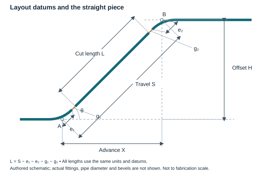
*Figure 18.2. The figure is an authored, single-plane geometric example. Dashed virtual intersections define S. The solid straight piece occupies L. Pipe diameter, actual elbow form and weld preparation are omitted. The drawing is not to fabrication scale. Its [structured dimensional method](assets/C17/c17-dimensional-methods.json) retains the defined datums and teaching calculation.*
Cut length differs from centerline travel by the actual fitting takeouts and specified joint gaps. Production dimensions also require the actual preparation and fabrication tolerance basis.
A rolled offset adds a second perpendicular separation. If **Hᵧ** and **H𝓏** are perpendicular offsets in two orthogonal directions, the resultant offset is **H = √(Hᵧ² + H𝓏²)**. The same triangle then determines travel and advance in the plane of that resultant. A roll angle, such as **φ = atan2(H𝓏, Hᵧ)**, locates the plane and preserves the signs of the two offsets.
All offsets must share a datum and units. Computing the resultant but omitting its orientation can produce the right travel length and the wrong spool. The completed elbow orientation requires stated axes and signs.
### A nozzle cutback locates a different part of the dimensional chain
A branch nozzle has to meet the intended parent surface while leaving its terminal at the specified position. The centerline layout alone does not locate the nozzle's profiled end. A **cutback** supplies a scalar reference from the header centerline to the nozzle's nearest point under a defined contact convention. It is useful in determining nozzle-pipe length, but it must remain attached to that convention. Nominal branch size, nozzle outside diameter and nozzle inside diameter are different quantities.
The straight-header method considered here is a centered, 90° nozzle whose **inside diameter rests on the header outside diameter**. A construction that instead inserts the nozzle outside diameter into a parent bore or opening has different contact and preparation datums. Do not transfer this cutback unchanged merely because both arrangements are called a stub-in. The centered long-radius-elbow method below has a different reference: the virtual intersection of the elbow's tangent centerlines. It is not the curvature center or the straight header's cross-sectional center.
To establish nozzle-pipe length:
- First establish the intended construction, parent geometry, actual nozzle bore, terminal face and component takeouts.
- Then determine the cutback.
- Close the axial dimension using those same references.
The final end profile, bevel, root opening, retained wall, reinforcement and attachment qualification remain separate work in [branch selection](#chapter-c07) and [joint preparation](#chapter-c16). A scalar cutback cannot generate the entire saddle or provide a weld-ready template around the nozzle circumference.
#### The centered 90° straight-header intersection
In the cross-section normal to a circular straight header, let \(D_h\) be header outside diameter and \(d_n\) nozzle inside diameter. The bore edges lie \(d_n/2\) to either side of the centered nozzle axis. At their intersection with the upper header outside surface, the cutback \(C_h\) satisfies
\[
C_h^2+\left(\frac{d_n}{2}\right)^2=\left(\frac{D_h}{2}\right)^2,
\qquad
C_h=\sqrt{\left(\frac{D_h}{2}\right)^2-\left(\frac{d_n}{2}\right)^2}.
\]
This is a right-triangle derivation of the depicted circular ID-to-OD contact. All quantities are lengths in one consistent unit. The radicand has squared-length units. Select the positive root for the upper-surface construction shown.
This point calculation does not include header ovality, an off-center branch, another angle or the nozzle wall/bevel profile. A nonnegative radicand is necessary for this intersection. If \(d_n>D_h\), the centered circular model has no real bore-edge contact. Another construction requires its own geometry.
A value for the missing intersection must not be invented.
Increasing the nozzle wall at fixed nozzle outside diameter reduces its bore and increases this geometric cutback. Header wall thickness does not appear in the equation because the contact is to its outside surface. It remains consequential to opening, reinforcement and welding. Neither effect should be inferred from nominal labels alone.
A useful historical dimensional comparison takes a nominal 6-inch header with 6.625-inch OD and a nominal 2-inch nozzle with 2.375-inch OD. The associated pipe-data basis lists a 0.154-inch standard wall and 2.067-inch bore, versus a 0.218-inch extra-strong wall and 1.939-inch bore. These are selected historical dimensions, not a present catalog or measured installed product. On those dimensions,
\[
C_{h,standard}=\sqrt{3.3125^2-1.0335^2}=3.14715\ \mathrm{in},
\]
\[
C_{h,heavier}=\sqrt{3.3125^2-0.9695^2}=3.16745\ \mathrm{in}.
\]
The selected standard-weight and extra-heavy cutback lookup entries are 3-1/8 and 3-3/16 inches respectively. Keep the lookup values and independently evaluated circle geometry distinguishable. Their increment and underlying fabrication conventions do not establish a universal rounding rule for every cell. They also do not establish that standard weight means Schedule 40 or extra heavy means Schedule 80 at every size.
*Table 18.1. Selected raw lookup cases for the centered straight-header ID-to-OD method. Header sizes are the column designation and nozzle sizes the row designation. [Structured values, dimensions and qualifications](assets/C17/c17-cutback-methods.json).*
| Nozzle / header nominal sizes, in. | Standard-weight entry, in. | Extra-heavy entry, in. | Meaning retained with the entry |
| --- | ---: | ---: | --- |
| 2 / 6 | 3-1/8 | 3-3/16 | Selected populated comparison; actual bore and OD still govern the geometric calculation |
| 2 / 2 | 0 | 0 | Literal zero in each lookup; not proof of zero circle-intersection cutback for actual dimensions |
| 3 / 2 | Not supplied | Not supplied | Blank case, not a zero or an inferred fabrication permission |
The diagonal zero is a consequential qualification. Using 2.375-inch header OD and 2.067-inch nozzle ID gives \(C_h=0.58484\) inch, not zero. The lookup does not explain a construction convention that reconciles its printed zero with that circle calculation. Retain the zero as a raw lookup entry and resolve the applicable physical detail before using it as a dimensional-chain input.
Do not silently replace it with 0.58484 or erase the distinction. Likewise, the blank nozzle-3/header-2 case supplies no table value. With the selected standard 3-inch nozzle bore of 3.068 inches and a 2.375-inch header OD, the radicand is negative for this model. That mathematical result does not prohibit every larger-outlet construction.
It identifies why this particular centered ID-to-OD intersection cannot supply the missing value.

*Figure 18.3. Authored circular contact geometry and a separate axial datum chain. The header OD and nozzle ID define \(C_h\). The nozzle outside-wall profile is omitted. The chain's terminal and takeout dimensions are hypothetical and are not drawn on the contact panel's scale. [Structured geometry and checked calculations](assets/C17/c17-cutback-methods.json) define the same references. This scalar reference is not a complete cutting template.*
#### The centered long-radius-elbow construction
A curved parent changes the datum as well as the contour. In the depicted ideal 90° elbow, extend the two tangent centerlines to their virtual intersection \(V\). The curvature center \(O\) lies one centerline radius \(R\) away in both coordinate directions. The nozzle axis follows the horizontal tangent-centerline extension through \(V\).
Its lower bore edge is a distance \(S\) below that axis. The outside bend circle has radius \(Z\), and its bore-edge contact is horizontally \(Y\) from \(O\). The printed relationships for this construction are
\[
Z=R+\frac{D_e}{2},\qquad S=\frac{d_n}{2},
\]
\[
Y^2=Z^2-(R+S)^2,\qquad X=R-Y.
\]
Here \(D_e\) is elbow outside diameter at the evaluated bend, and \(d_n\) is nozzle inside diameter. The actual centerline bend radius is \(R\). The local lengths \(Z,S,Y,X\) use the same units. \(R+S\) is the vertical separation from curvature center to the lower bore edge.
\(X\) is the signed horizontal contact coordinate from \(V\), positive toward the elbow's horizontal tangent end. These symbols belong to this elbow construction, not to the preceding offset triangle. A component center-to-end dimension that includes an additional straight tangent is not automatically its bend radius.
Use \(Y=+\sqrt{Z^2-(R+S)^2}\) for the contact branch depicted on the left side of the curvature center. The negative square-root branch would locate another circle point. For this contact branch:
- Evaluate the radicand.
- Verify that the point lies on the actual 90° bend surface.
- Verify that both bore-edge locations and the nozzle wall/preparation fit the intended connection.
- Verify that the sign of \(X\) agrees with the drawing.
An elbow's actual contour, straight ends, ovality or another branch location can invalidate the ideal circle even when the arithmetic has a real root.
For a worked geometric case, assume the selected 6.625-inch elbow OD, a 2.067-inch nozzle bore and an actual centerline radius of 9.000 inches. The radius is an explicit teaching input, not a dimension inferred solely from the words “long radius.” Then \(Z=12.3125\) inches, \(S=1.0335\) inches and
\[
Y=\sqrt{12.3125^2-10.0335^2}=7.13628\ \mathrm{in},
\qquad X=9.000-7.13628=1.86372\ \mathrm{in}.
\]
The selected standard-weight elbow lookup for nozzle 2 / elbow 6 is 1-7/8 inches. It is a separate raw lookup beside this explicitly dimensioned calculation, not an identity claimed for every table entry or actual elbow.
The boundaries show why a real radicand is not sufficient. At \(d_n=D_e\), \(Y=0\) and the indicated lower-edge contact reaches the tangent-end boundary of the ideal quarter circle. That degeneracy does not establish a usable branch attachment. For a hypothetical \(R=0.75\), \(D_e=0.84\) and \(d_n=0.10\) inches, the radicand is positive but \(X=-0.10376\) inch.
That real contact lies on the opposite side of \(V\) from the positive-\(X\) layout. Taking its absolute value would move the endpoint. Re-establish the actual datum and eligible physical detail before carrying such a signed result into a cut length. If the nozzle bore exceeds the elbow OD in this construction, the radicand becomes negative and provides no real contact.
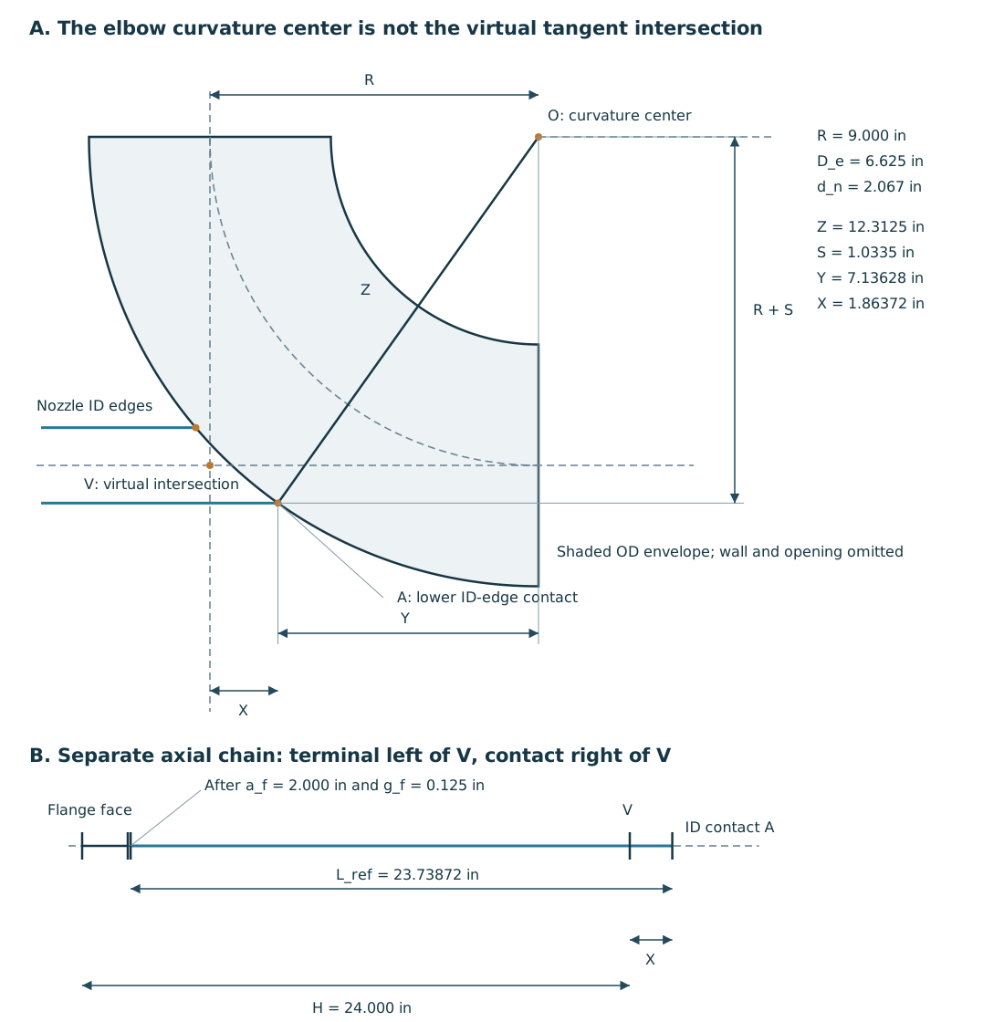
*Figure 18.4. Authored ideal 90° elbow geometry. The curvature center \(O\), virtual tangent intersection \(V\), lower bore-edge contact and tangent end are distinct references. The positive \(Y\) branch and \(X=R-Y\) are shown. A separate chain panel locates a hypothetical flange face to the left of \(V\). It does not put that face in the contact panel at a fabricated distance. [Structured points, quantities and cases](assets/C17/c17-cutback-methods.json) accompany the figure.*
*Actual end profile, wall and qualified attachment are not supplied.*
#### Close the nozzle length using the selected reference
The sign of a subtraction follows the physical datum chain. For the straight-header example, put the flange terminal face a perpendicular distance \(H\) above the header centerline. Let \(a_f\) be its face-to-nozzle-welding-end takeout and \(g_f\) the specified flange-to-nozzle butt-weld root gap. If the nozzle's reference length \(L_{ref}\) is measured from that butt end to the bore-edge intersection used for \(C_h\),
\[
L_{ref}=H-a_f-g_f-C_h.
\]
Assume hypothetical \(H=24.000\), \(a_f=2.000\) and \(g_f=0.125\) inches. The actual-dimension circle result for the standard bore gives \(L_{ref}=18.72785\) inches. The heavier bore gives 18.70755 inches. Using the separate selected lookup values would instead give 18.75000 and 18.68750 inches.
These computations retain which cutback basis produced the dimension. They do not justify choosing the shorter answer or issuing five-decimal shop dimensions. The applicable physical detail, product dimensions, drawing convention and fabrication precision must establish the production value.
For the elbow example, place the hypothetical flange face \(H=24.000\) inches **to the left** of \(V\). The contact is \(X=1.86372\) inches to its right. With the same hypothetical \(a_f\) and \(g_f\),
\[
L_{ref}=H+X-a_f-g_f=23.73872\ \mathrm{in}.
\]
This is a plus sign because the defined contact lies beyond the virtual intersection from the terminal. Subtracting \(X\) as though it were the straight-header \(C_h\) would give 20.01128 inches and locate another end. The separate elbow lookup value 1-7/8 inches would give 23.75000 inches on its own basis. Neither the curvature-center radius \(Z\) nor the elbow takeout \(R\) can be substituted for \(X\).
These are nozzle lengths **on the stated bore-edge reference**, not an automatic full-wall blank or weld-ready profile. A drawing may define a different long-point, short-point or stock-cut convention. Preserve the relation from this reference to its actual profiled end, joint preparation and trimming allowance rather than inventing those unprovided dimensions. The flange root gap used here is a specified teaching input at one named joint. It is not a general branch-mouth gap.
Actual diameters/radius, the selected ID-to-OD construction, any lookup row/column, signed takeouts and available preparation access govern the cut instruction.
After forming and joining, evaluate the completed terminal-to-parent relationship on those same datums.
A closed scalar chain can still have the wrong branch orientation, a damaged bore or an unqualified opening. The useful output is a traceable dimensional instruction that can be made and checked, connected to the separately established branch and welding basis.
## Tolerances, field fit and equipment connections
A fabrication tolerance bounds departure from a specified dimension. It does not change the nominal design dimension and does not authorize any stress produced by forcing the completed parts together. Tolerances on a spool, equipment setting and structural construction can accumulate at a closing connection. The accumulated discrepancy has translation and orientation: a line can meet the nozzle position but approach it at the wrong angle.
As an example of a bounded dimensional specification, the following limits apply when a fabrication basis adopts this particular length-tolerance schedule. They are not default tolerances for every piping system.
*Table 18.2. Conditional spool length-tolerance schedule, retained in the [structured fabrication tables](assets/C17/c17-fabrication-tables.json).*
| Controlled dimension | Specified length < 1.5 m | Specified length ≥ 1.5 m |
|---|---:|---:|
| Distance between two parallel or crossing centerlines | ±1.5 mm | ±3 mm |
| Centerline to flange face | ±1.5 mm | ±3 mm |
| Flange face to flange face | ±1.5 mm | ±3 mm |
The boundary at 1.5 m belongs to the larger-length category in this schedule. Flange-face alignment has separate criteria. The length table does not supply angular or lateral alignment limits. Other specifications use their own dimensional and alignment bases, and their values should be carried into the work package rather than mixed with this example.
Terminal tolerances can oppose and accumulate at closure; angular errors and the closing spool's own error are additional inputs. Tolerance accumulation does not establish permissible flange pull-up or equipment load, and statistical cancellation requires its own population/dependence basis.
A planned field-fit length provides material that can be measured and trimmed after the neighboring equipment and spools have reached their actual positions. A closing piece can then be prepared and joined without making the equipment nozzle absorb the dimensional discrepancy. The field joint needs sufficient straight length and access for cutting, beveling, fit-up, welding and examination. It also requires a defined test route. A fitting-to-fitting connection can remove all of this useful adjustment space. Including a suitable spool length in a pump suction or air-cooler connection is therefore a constructibility decision with mechanical consequences, not simply a drafting convenience.
Before closure, compare actual terminal location, flange face orientation, bolt-hole orientation, pipe/support position and any specified installation preset. Correct the cause of a mismatch within an accepted fabrication or engineering method. Cutting and remaking a piece may be preferable to retaining a strained fit. Heating or forcing a completed spool changes its material and mechanical history.
It needs a procedure suitable for the material, service and previous treatment. The alternatives differ in cost, reexamination and treatment work. A flange tightened until it appears aligned has concealed the discrepancy rather than demonstrated its acceptability.
Designed cold spring is a separate matter. It is an intentional installed displacement with a defined method and evaluation, addressed with [flexibility and equipment loads](#chapter-c09). Random construction pull-up must not be renamed cold spring. Likewise, a pipe that is flexible enough to move into position may still transfer a consequential force or moment to a machine. The installation check preserves the actual conditions assumed in the mechanical evaluation.
### Select a correction that preserves the material and installed result
Cutting and remaking a spool exchanges additional joint work for an unstrained fit. Heating or forcing it exchanges that work for another material and mechanical history. A heater-coil procedure ranks cutting/rewelding first, local non-uniform heating or cooling second, and force with heating third. The procedure requires the correction method to be established before work. Rewelding reopens the joint's qualification, examination and treatment. A heated correction requires its own temperature measurement, cooling and any renewed properties or PWHT.
For a particular carbon-steel route without required PWHT, the heated-correction maximum is 600°C with still-air cooling. Its temperature-crayon method reserves a 50°C margin, so the indicated maximum is 550°C. Carbon steel that requires PWHT instead retains its treatment maximum and either a compliant thermal cycle or renewed treatment of the corrected region, without quenching. The Cr-Mo route adds hardness checks on the heated/forced area under its defined criterion. These are scoped correction conditions, not temperatures at which ordinary installation pull-up becomes acceptable. The [structured correction comparison](assets/C17/c17-correction-methods.json) retains the distinctions.
The stainless variants demonstrate why selecting a stricter number is insufficient. The heater-coil route permits necessary force with brief heating limited to 500°C. A separate general spool route limits heating to 650°C and prohibits force for austenitic stainless. Each uses its specified measurement margin and complete material/work basis. Combining the coil temperature with the general route's force rule would create a third procedure with no supplied warrant. After cooling, the selected method requires renewed terminal/face/support checks and affected treatment/examination. The equipment connection must not retain a hidden strain.
## Keeping material identity through manufacture
Material identity must survive cutting, assembly and installation so the actual grade, wall, heat-treatment and impact-test condition remain attached to the installed item. A physical marking must match its certificate and specified product.
Color coding can help personnel distinguish material groups quickly, but it supplements the specified markings and records. A color is not a material certificate. Schemes also differ between projects. Marking materials must be compatible with the substrate and service. Do not cover the information needed to identify the product or contaminate weld bevels, threads, internal surfaces or gasket seating faces. A replacement piece that looks identical can differ in grade, wall, heat treatment or impact-test condition.
The procurement/construction basis determines certificate, marking and examination requirements. Some complete controlled-traceability routes permit reduced later alloy identification; others require PMI in addition. Lost identity needs its specified recovery route.
Positive material identification answers a material-composition question within the capability of the selected method. It does not by itself establish every required mechanical property, original heat treatment or certification relationship. Traceability, PMI, dimensional inspection and weld examination therefore remain complementary. Their detailed material and examination roles are developed in [materials and procurement](#chapter-c02) and [welding and examination](#chapter-c16).
A proposed substitution should state the original requirement, the proposed product and the resulting differences. A change in wall thickness may alter fitting alignment and weight as well as pressure capacity. A change in grade may alter welding, heat treatment and corrosion behavior. The accepted disposition must reach the drawings, material list and procedures before the changed item is incorporated. Recording only the supplier's replacement part number leaves these interfaces unresolved.
### Carry the heat lot and component population through verification
A material-identity check must preserve which items its result represents. One fabrication procedure performs the 300-series stainless component analyses on completed spools before any required PWHT. Component selection is distributed evenly among the completed spools. It uses at least 10% of each fitting type per heat lot and 10% of each flange type per heat lot.
It separately analyzes straight pipe on at least 10% of completed spools for each pipe diameter. Fittings and flanges without identifiable heat lots receive 100% analysis under that method. Other listed alloys have their own 100% component scope. These are identity populations, not the percentage of welds required for radiography or hardness testing.
Each fitting/flange type and heat lot is a separate sampling population. Missing heat-lot identity invokes the specified 100% scope rather than increasing an identified lot's denominator. The [structured PMI companion](assets/C17/c17-pmi-populations.json) retains scoped populations and hypothetical arithmetic.
The selected analyzer must resolve the required alloy elements. If it cannot identify a component, an accepted laboratory route can be necessary, with sample removal and traceability preserving both identity and remaining wall. In the specified response, a measured major alloy element below its required range rejects the respective heat lot unless the permitted wet-chemistry check determines its disposition. Rejected components without lot identity expand analysis to similar unidentified components. A higher-than-specified measured alloy concentration is referred for its own acceptance disposition. “More alloy” is not automatically equivalent to the ordered material.
Another fabrication basis instead permits omission of post-assembly alloy identification when its complete auditable chain of procurement marking/certificates, receipt matching, grade-segregated storage, controlled issue and maintained fabrication segregation is followed. Failure of any stage invokes completed-item PMI under that basis. A heater-coil procedure independently calls for alloy-element verification of materials and weld deposits after fabrication. These are different complete identity routes. A complete certificate file does not waive a specified sampling requirement in the first. A spot analysis does not recreate a lost heat-to-installed-item relationship in the second.
### Make the correct reassembly physically recognizable
Repeated removable spools can have similar configurations but different metallurgy. An adopted arrangement can give them different shapes or lengths. A lower-alloy item then cannot readily occupy the higher-alloy location. This physical prevention complements material marking and the restored-item check. A shape alone does not certify composition or condition. Keep the differentiating geometry in the fabrication detail rather than leave interchange prevention to a temporary tag that can be lost.
An injection quill adds orientation to that identity question. Under a specified concurrent-flow route, the detail identifies bulk-flow direction with an arrow and a secondary positive reference such as a coordinate or downstream equipment item. The quill's opening points in that same direction. One-way installation geometry, or matching downstream alignment tabs/pins on the quill and mating flange, makes the intended orientation physically recognizable.
That route retains its injection/mixing and downstream-erosion assessment. Keying does not authorize concurrent flow for every process. The [structured reassembly-prevention examples](assets/C17/c17-reassembly-prevention.json) retain the two different functions.
The detail and P&ID must preserve the quill's positive reference, keying, material and discharge orientation through withdrawal/replacement. Changed mating parts reopen that check. See [change records](#chapter-c21).
## Preparing and assembling the joints
Cutting and beveling establish the joint geometry and expose the surface that will be joined. Mechanical, thermal, plasma and water cutting have different material applicability and finishing requirements. Thermal cuts can leave oxides or an affected surface that must be removed under the specified preparation procedure. Stainless steel preparation also requires control of contamination and dedicated tools where prescribed. An allowance left for field cutting is useful only if the final cut can be prepared correctly at site. A shop-prepared bevel may have to be removed when that allowance is trimmed.
Butt-weld fit-up controls root gap, bore alignment and the relationship between unequal wall or bore dimensions. A permitted taper or transition must preserve the minimum required wall, including applicable allowances. Grinding until two bores appear flush is not a sufficient dimensional criterion. The joint preparation and production welding route are established in [the welding procedure](#chapter-c16). This chapter carries them into the sequence, space and actual dimensions of the assembly.
Socket joints illustrate why appearance alone is inadequate. A square, deburred end enters a socket, but a specified clearance is retained between the pipe end and the socket stop before welding. The clearance avoids the adverse shrinkage/restraint condition associated with a pipe bottomed hard against the stop. Insertion and clearance are separate dimensions. A satisfactory external fillet does not show that the internal fit-up was correct. The specified gap, insertion and verification method must therefore be established before concealment.
Threaded joints require the intended thread form, engagement and condition. Where a specified joint is to be seal welded, the adopted procedure determines preparation and excludes incompatible sealant or lubricant from that weld. Seal welding is not a general remedy for every threaded connection. Welding or heat treatment can also affect threads. The fabrication procedure may require checking or chasing them afterward. Thermowell and other insert openings must remain unobstructed.
At flanges, face orientation and bolt-hole orientation are independent checks. A face can be perpendicular to its pipe axis but rotated incorrectly relative to the mating flange. The specified gasket, bolting, lubricant and tightening method then establish the joint assembly. Their detailed selection belongs in [pressure-retaining joints](#chapter-c03). Use of a long stud, a different lubricant or additional washers can alter the actual assembly even when the flange rating is unchanged. Bolting must not become a tool for absorbing an unreviewed piping mismatch.
Branch and attachment sequence affects examination access. A branch root may need internal examination before its next component is fitted. A reinforcing pad may need to follow examination of the pressure-containing weld but precede required heat treatment. Support shoes and other attachments on a line requiring PWHT need locations and welding sequence compatible with that treatment.
Source specifications differ on longitudinal seam orientation, weld spacing and attachment location. The fabrication drawing should carry the selected basis explicitly. A generic preference such as “keep welds away from supports” cannot replace its actual conditions or exceptions.
Valves add an internal assembly that fabrication can damage. Welding heat can impair soft seats or distort bodies. Flushing debris can score seating surfaces. Manufacturer instructions, the specified valve condition during welding and the sequence of flushing or temporary-spool use therefore belong in the work package.
A check valve needs the correct flow orientation, and any shipping restraint on its disc must be removed at the intended stage. A butterfly valve needs mating bore clearance and a suitable installation position so that its disc and resilient facing are not damaged or jammed. Completing a mechanical operating check after installation verifies a function that an external dimensional check cannot establish.
### Sealing threads and bridging a short branch root
A short threaded branch root concentrates several interfaces into little space. These include the run-to-branch fitting attachment, nipple or valve male end, engaged threads and valve body. The weld placed at a threaded joint must therefore be described by its actual purpose and coverage. A seal weld can close the leakage path and cover exposed thread notches. It does not automatically turn a threaded assembly into a qualified full-strength welded joint. The thread engagement remains a distinct fit-up condition, and the run-to-fitting attachment remains a separate weld.

*Figure 18.5. Conceptual sections for a selected short branch-root detail. Hatched gray is component material. Blue is the selected deposited weld. Internal engagement is shown separately from the exterior coverage. The two bridge alternatives preserve the short nipple and integral male-ended valve arrangements.* [Structured geometry and conditions](assets/C17/c17-seal-bridge-root.json).
In the selected seal-weld detail, the weld covers **all exposed threads, including thread-runout scratches**, and covers the entire fitting face at the joint. It blends smoothly into the pipe without undercut. The depicted sealing profile is flat or slightly concave rather than convex. These coverage and contour instructions address the local thread/runout geometry.
A small bead that leaves the last thread scratch uncovered has not achieved that detail, even if a subsequent leak test finds no leakage. The selected assembly is made up dry, without thread compound or PTFE tape, and with proper thread engagement before welding. Establish these conditions before the weld conceals them.
The bridge detail addresses the region between the branch fitting and the valve hub in **severe cyclic service**. Its two physical alternatives are a short nipple with a socket-welding or threaded valve, and a valve with a male end. In the nipple alternative the selected seal-weld buildup extends to the **full valve-hub diameter for the full nipple length**. This is additional deposited geometry spanning the short root region, rather than two isolated sealing beads at its ends.
The male-ended alternative removes the separate nipple but retains a defined bridge between fitting and valve. The run attachment shown with these alternatives is on a **2 in or larger line**. That depicted condition does not establish a general permission for every run size or branch fitting.
The accompanying short-nipple detail has a local bridging instruction. It applies where the **remaining spacing shown between the separate seal-weld regions is less than 1/4 in**, to avoid a notch effect. That spacing is not the nipple's full length **L** between its engaged ends. Keep both dimensions identifiable: “make the nipple as short as practical” must not leave an unexamined narrow groove between adjacent beads. The 1/4 in condition belongs to this selected detail and its geometry, rather than a universal bridge-welding threshold. A fabrication drawing using it needs to identify the intended fitting, nipple, valve end and weld boundaries so that its local spacing can actually be checked.
Bridging changes the exterior section and the way local loads pass through it. Its presence does not establish a fatigue rating or a pressure-strength calculation. Material, wall, engagement, fitting/valve construction, cyclic loading and the qualified welding route still govern adoption. The selected detail cannot be applied by adding weld metal to any short threaded nipple. Heat input and any required heat treatment must also be compatible with the valve internals and the selected preparation route. [Valve thermal state and reassembly](#c17-valve-thermal-state) develops that interface; [small-bore branch integrity](#chapter-c07) connects the root to its support and vibration environment.
Thread engagement/cleanliness must be established before concealment; actual thread-runout enclosure, contour, undercut and bridge extent/hub transition are examined afterward. Pressure and functional tests do not recover an unobserved internal fit-up dimension. See [production control](#c16-production-control) and [weld-symbol interpretation](#c17-weld-symbol-reading).
### Treat the valve as an assembly during welding and PWHT
The required weld thermal cycle and the valve's internal heat tolerance must be achieved together. Seat distortion, damaged soft seats, packing or gaskets can leave a valve that is pressure-connected but cannot perform its shutoff function. Valve-body temperature, weld-region temperature and bonnet temperature are different observations. A heater setting or one favorable weld reading does not establish that the protected parts remained suitable.
Under a particular small carbon-steel valve procedure, socket/seal-weld work on P-1 valves through NPS 1½ is followed by its defined local treatment arrangement. Both welds are heated simultaneously, while the body and adjoining pipe are insulated and the upper bonnet is kept uninsulated and away from directly applied heat. The arrangement identifies weld/body preheat and interpass locations and a separate bonnet interpass location, with external thermocouples for treatment. Its valve position during PWHT—closed then backed off two handwheel turns—and its means of limiting convection belong to that particular valve/treatment method, not to every valve being welded.
A different class-specific PWHT preparation requires bolted bonnets/covers so that the bonnet or cover, gasket, internals and trim can be removed and tagged before stress relief. Restore the correct identified assembly with new gaskets after the required treatment and examination. The temporary body configuration must remain identifiable. Loose trim from a similar valve is not a verified substitute. This method does not prescribe an oven temperature or authorize dismantling another valve design.
A separate, specific soft-seat socket-valve procedure permits welding without disassembly for its specified construction in ¾-, 1- and 1½-in sizes. It uses its permitted arc processes and rod size, cools the body to 200°F between passes, and calls for prompt cooling after the last pass. A body reading above 400°F immediately after a pass triggers disassembly and visual examination for seat damage, with replacement if damaged. That scoped protection method is different from simply applying the small P-1 PWHT arrangement or removing internals under the class-specific preparation above.
*Table 18.3. Assembly states and thermal questions, with [structured route conditions](assets/C17/c17-valve-thermal-state.json).*
| Bounded route | Temporary state or protection | Evidence needed for the next state |
|---|---|---|
| Specified small P-1 socket/seal valve welding and local PWHT | Defined joint/body heating and insulation; bonnet protection; prescribed treatment position | Actual measurement locations, completed thermal cycle, required examinations and functional condition |
| Class-specific valve preparation where PWHT is required | Bolted bonnet/cover and vulnerable parts removed, tagged and protected | Correct parts restored, new gaskets, required joint/assembly checks and test disposition |
| Specified soft-seat socket-valve welding without disassembly | Model-qualified controlled passes and body cooling; overheat response | Body-temperature observations, condition after an overheat event, reassembly/packing and operating checks |
The work package selects a complete route from the actual valve construction, material, seals, joining method and treatment duty. Other adopted soft-seat routes use an open closure member during welding. A gate/globe seating-protection route can instead require closed then half a turn open. Neither position instruction supplies the other's thermal or disassembly permission. After restoration, check orientation, complete operating travel, packing/gasket condition and the required containment evidence. A valve that cycles freely still needs its prescribed pressure boundary verification, while a leak-free body alone does not establish seat performance.
### Locate the observations before applying the thermal cycle
The selected small P-1 valve method becomes more intelligible when its observation points and treatment envelope are drawn separately. The first panel identifies three locations on the valve assembly: **bonnet interpass**, **body-joint preheat and interpass**, and **body preheat and interpass**. Here *body joint* names the region at the bonnet/body connection. It is not a label for the pipe-to-valve socket weld. A reading at that connection addresses a different part of the assembly from a reading at the lower body or a weld-region thermocouple during treatment. Record which location produced each observation so that an acceptable body temperature cannot be mistaken for an acceptable bonnet condition.

*Figure 18.6. Selected procedure for socket/seal welding of carbon-steel P-1 valves through NPS 1½. Observation geometry at left and treatment geometry at right are different stages of the same bounded route. The upper bonnet is uninsulated and receives no directly applied heat. Heat conducted from the body remains possible.* [Structured observation and arrangement data](assets/C17/c17-valve-observation-geometry.json).
This selected SMAW route retains a **1/16 in minimum socket gap during tacking**, filler of the same analysis as the base material and its preferred low-hydrogen electrode with maximum 0.05% carbon. Its specified preheat/interpass range applies to pipe and valve body under the adopted B31.3/welding basis. The location diagram supplies no missing temperature setpoint.
During local PWHT, **both welds are heated simultaneously** by the selected electrical-resistance or halogen-quartz route. The treatment thermocouple/external observation locations are associated with the heated joint regions. Insulation covers the body, welds and adjoining pipe while leaving the upper bonnet exposed. For the electrical-coil arrangement, the selected insulation extends at least **6 in along the pipe on each side of the valve** to provide a gradual temperature gradient.
The halogen-quartz alternative requires its special application arrangement. It must not simply inherit every coil placement from the drawing. Heating rate, cooling rate and treatment temperature follow the adopted requirements, with a selected **½ hour hold at temperature**.
The insulation-thickness statement in this historical route gives **at least 1 in**, paired in its text with **24.4 mm**. Those printed units do not agree. The conversion of 1 in is 25.4 mm. When recovering the route, retain that discrepancy.
Before specifying or purchasing insulation, resolve the adopted thickness in the work package. The figure therefore identifies an insulation envelope and its selected inch condition, without silently treating 24.4 mm as an equivalent or choosing an undocumented substitute. The insulation material likewise needs the selected approval basis, not merely a similar appearance.
The thermal arrangement includes the valve's mechanical state. In this route the valve is closed completely and then backed off **two full handwheel revolutions during PWHT**. Short open pipe ends are sealed where required to prevent convection heat loss. These provisions are coupled to this valve/treatment method, rather than instructions to apply to another design.
An upper bonnet that is uninsulated and free of directly applied heat may still warm by conduction. Its separate observation matters. A coil controller or a good weld-temperature trace alone does not establish the packing, gasket or valve assembly condition.
The assembled-valve route does not inherit removed-internals or soft-seat-cooling permissions. Its two-turn PWHT position does not apply to those routes. Location-specific thermal evidence, final examination and restored operating/containment checks remain required; see [thermal controls](#c16-thermal-controls) and [hardness locations](#c16-hardness-location-references).
## Bends and fabricated changes of direction
A pipe bend makes a change of direction within a length of pipe. A welded elbow introduces a manufactured component and its joining work. A mitered change of direction uses oblique cut-and-weld segments. These alternatives occupy different space and create different fabrication, inspection, flow and mechanical conditions. Where large-size fittings are unavailable or a particular radius is useful, a fabricated alternative may be practical. Geometry alone does not establish pressure or fatigue suitability.
A larger bend radius consumes more space. A tighter bend subjects the material to greater deformation. Bending can change wall thickness and cross-sectional shape and can produce wrinkles or cracks. The finished bend must therefore be evaluated for remaining wall, ovality or flattening, surface condition, dimensions and material properties. If the line is to be pigged, its bore and radius must also permit the required passage. The original pipe schedule does not demonstrate the minimum wall remaining after bending.
Cold bending, hot bending and induction bending have distinct process histories. Cold forming introduces deformation without the hot-forming temperature cycle. Hot forming requires controlled heating and cooling. In induction bending, a narrow circumferential band is heated while neighboring pipe supplies support as the bend advances. The forming speed, heated-band width, temperature measurement and cooling conditions become production variables. A qualified induction-bending program connects those variables with tested bends; production dimensional and material checks establish whether the delivered items remain within that basis.
The material and service boundaries matter. A carbon-steel bend, a quenched-and-tempered low-alloy bend and a duplex stainless-steel bend cannot inherit one heat-treatment rule from their common shape. The applicable procedure considers their original condition and the change caused by forming. Some fabrication specifications prescribe five-diameter or six-diameter minimum radii, while another provides selected radii and more detailed material/process conditions. Choosing the largest number across those practices would still fail to determine process qualification, remaining wall or service applicability. A prohibited field hot-bending operation likewise cannot be made acceptable merely by using a generous radius.
For a prescribed bend acceptance schedule, measurements of thinning, flattening and wrinkles are made against that schedule and the applicable pressure-design wall requirement. The definition of a wrinkle matters: a crest-to-valley height and its wavelength are not interchangeable with an overall diameter measurement. Cracks require their own disposition. An unacceptable crack must not be hidden by a cosmetic weld repair. The geometry and material examinations are distinct from the later [test of the assembled line](#chapter-c18).
The spool detail also has to distinguish straight tangents from the curved portion. For an ideal circular centerline bend, the arc length is **Rθ**, where R is centerline radius and θ is the change of direction in radians. This is a geometric length, not a universal blank-cut instruction. The bending process, straight tangents, trimming allowance and actual finished dimensions still determine the required stock. Bend tables are useful only with their accompanying radius, angle and dimension diagram. A number taken from a table without its geometric letter or units can describe a different part of the bend.
Mitered elbows require similar discipline. Their joint count and angles affect flow disturbance and fabrication work. Fewer segments may reduce first cost while making a more abrupt change of direction. Their allowed pressure/service, wall and examination conditions must come from the selected design and fabrication basis. A table of miter cut dimensions teaches how to lay out a permitted configuration. It is not permission to replace any standard elbow with a miter.
### Subdivide the turn, then locate the miter cuts
A segmented miter changes direction at its joints. Its layout begins with four inputs. These are required total turn **Θ**, number of miter joints **m**, actual pipe outside diameter **d**, and selected centerline layout radius **R**. Here R locates the circular construction used to lay out the tangent segments. The finished centerline is a polygon, not a smooth arc. The layout-circle, segment-axis, projected-terminal and inside/outside-edge references are distinct.

*Figure 18.7. Selected planar equal-turn layouts and projected cut-plane references. The total turn, direction change at a joint and inclination of each cut from a square end are distinct angles. These are geometric layouts for an already permitted configuration, not developed-shell cutting templates or pressure/fatigue acceptance.* [Structured method, exact teaching row and calculations](assets/C17/c17-segmented-miter-layout.json).
For equal direction changes, each joint turns the adjacent pipe axes through **δ = Θ/m**. Each mating cut plane bisects that change, giving **α = δ/2 = Θ/(2m)** as its inclination away from a square end. Thus a single-joint 30°, 45° or 60° turn has cuts inclined by 15°, 22½° or 30°, respectively. For a 90° assembly with two, three or four joints, the axes change by 45°, 30° or 22½° at each joint.
Each end cut is inclined by 22½°, 15° or 11¼°, respectively. There are m + 1 pieces. Calling a four-joint assembly “four pieces,” or cutting each end at the full direction-change angle, produces a different assembly.
In the projected circular construction, the first and last radial sectors are half sectors, with full sectors between them. A 90° two-joint layout therefore has sectors **22½° + 45° + 22½°**. A three-joint layout has **15° + 30° + 30° + 15°**. A four-joint layout has **11¼° + 22½° + 22½° + 22½° + 11¼°**.
Those sector angles locate tangency points and cut intersections. They must not be added a second time as extra pipe-axis turns. Terminal faces in this construction are square to their terminal axes and located at the first/last tangency points. Additional straight tangents require their own dimensions.
Let **r = d/2** and **a = r tan α**. For a cut through a straight circular pipe, a is an axial setback in the plane of the turn. It extends from the cut's centerline intersection to an extreme outside-surface edge. The long-to-short difference of one oblique end is **2a = d tan α**.
This uses outside diameter, not nominal size, inside diameter or wall thickness. For an interior piece bounded by two symmetric cuts, let **ℓc** be its axial centerline length between those cut-plane intersections. The outer and inner extreme axial lengths are then:
**ℓouter = ℓc + 2a**; **ℓinner = ℓc − 2a**.
The construction radius gives **ℓc = 2R tan α** for a full interior tangent segment. Each unextended terminal segment has centerline length **R tan α**. For a terminal piece with one square end and one oblique end, the corresponding extremes differ from its centerline length by only **a**, not 2a. This distinction prevents applying an interior-piece allowance to an end piece. All lengths are axial or projected distances between the named planes, rather than lengths measured along an oblique edge or around the circumference.
| Selected historical layout references | Meaning in its own drawing | Use boundary |
| --- | --- | --- |
| Single-joint 30°/45°/60° columns | Axial half-setback between cut centerline and extreme edge for that total turn | Select total turn first; do not read the column angle as each cut's inclination |
| Two-joint 90° layout A | Half-setback at the selected 22½° cut | An end-cut reference, not a centerline segment length |
| Two-joint 90° layout D / E / F | Outer / centerline / inner axial lengths of the middle piece | D and F bound the same selected piece; their mean can check E |
| Two-joint layout B / C | Separate projected terminal reference intervals shown at the end of that layout | Retain their actual terminal lines; do not substitute a middle-piece length |
| Three-joint layout G / H / I and J / K / L | Its own end references and outer / centerline / inner interior-piece lengths | G–L belong to the 15° cut configuration |
| Four-joint layout M / N / P and S / T / U | Its own end references and outer / centerline / inner interior-piece lengths | M–U belong to the 11¼° cut configuration |
A table lookup must bind the configuration, size or actual diameter basis, radius, units and dimension letter together. The historical two-joint table prints Size and R. Its companion three/four-joint table prints dimension letters but does **not** print Size or R row labels. Row position alone is insufficient authority to attach a nominal size/radius to a companion value. The geometric relations above can support an independently defined layout. They do not certify an undocumented row join or turn every historical rounded dimension into an exact trigonometric result.
For a **selected table-based dimensional closure**, use the explicitly labeled Size 6 row of the two-joint 90° layout. Its R is 9 in, and A is 1⅜ in. The middle-piece lengths are **D = 10 3/16 in, E = 7 7/16 in, F = 4 11/16 in**. The row's diagram and fractional dimensions are the example inputs, not a newly selected production spool. With these fractions:
**(D + F)/2 = (10.1875 + 4.6875)/2 = 7.4375 in = E**;
**D − E = E − F = 2.75 in = 2A**.
The outer-to-inner difference is **5.5 in = 4A**. This checks that the three cut-length references describe the same symmetric middle piece. Independently, the ideal centerline construction gives **2 × 9 × tan 22½° = 7.455844 in**, about **0.018344 in greater** than the tabulated E. That small difference is retained as a difference between ideal geometry and the printed fractional table, not silently corrected or declared a fabrication tolerance. The row does not print actual outside diameter, so this example does not infer d from nominal Size 6 or calculate an undocumented outside-diameter allowance.
These lengths locate ideal cut planes. Stock cutting still needs the actual bevel/root-face preparation, fit-up gap, cutting kerf and trimming method, and the chosen finished dimensional datum. A kerf is material removed by the cutting operation. It is not a universal amount to add to every long-point dimension.
Reusing complementary cuts, reversing a piece and rotating it about its axis can change which marked edges meet. Keep the turn plane, inside/outside marks and piece sequence visible through fit-up. A reversed asymmetric piece or an unplanned axial rotation can introduce a different orientation even if individual long-point measurements agree.
Completed fit-up must preserve total axis turn, piece count, cut inclination, inner/outer orientation, terminal positions and actual root preparation, remaining wall, weld spacing and access. [Spool datums](#c17-spool-description), [weld symbols](#c17-weld-symbol-reading) and [production control](#c16-production-control) carry the layout into a qualified joining route. Material/wall, examination, allowed pressure/service and cyclic/vibration suitability remain separate: geometric closure does not permit replacing a manufactured elbow.
### Measure the formed bend and qualify its production route
The bend's geometric observations remain separate from its pressure-design wall and material condition. One acceptance basis limits a wrinkle's vertical height $h$ from the average elevation of two adjoining crests to the intervening valley. It requires gradual blending of the wave shape, $h\le0.03D_n$, and crest spacing $\lambda$ relative to that height of $\lambda/h\ge12$, where $D_n$ is the nominal pipe-size length under that basis. All lengths use consistent units. These two inequalities describe different aspects of a wrinkle. They do not define overall ovality or permit a crack.
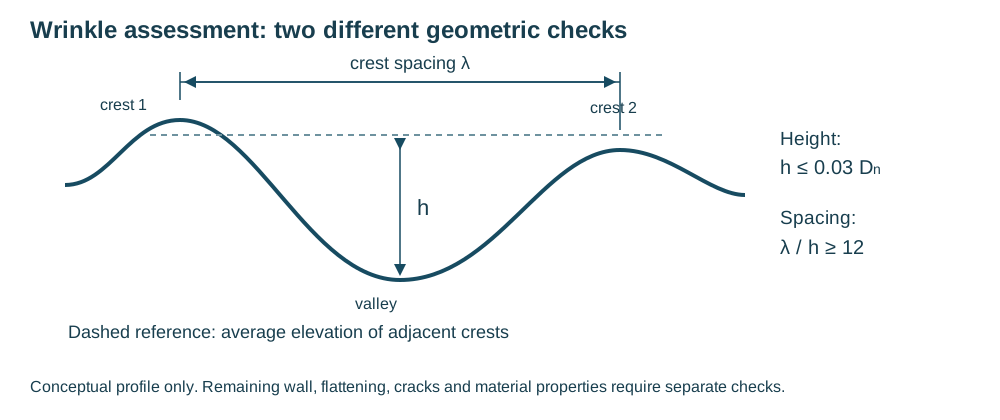
*Figure 18.8. Authored measurement geometry for the stated wrinkle method, with [structured geometry, conditions and hypothetical checks](assets/C17/c17-bend-assessment.json). Unequal crest elevations use their average as the height reference. This profile is not a manufactured bend or a permitted forming setup.*
Wrinkle-height and crest-spacing conditions must both be satisfied. Remaining wall, flattening, cracks, dimensional fit and properties have separate criteria; the nominal-size length in this wrinkle method is not outside diameter in a strain formula.
An induction-bending qualification likewise does not replace production observations. One route qualifies at least two bends per material type at the smallest and largest diameter/wall combinations. Low-alloy work adds its stated heat-specific test bends and microstructure examination. Test bends cannot be repaired by welding.
For production, every bend receives its dimensional and visual checks after forming and heat treatment. One bend of each defined production run receives the specified wall, surface and hardness examinations. A run retains the same size, wall, material and controlled bending parameters. A changed setup cannot quietly remain inside the old representative population.
Under that production method, wall measurements cover complete inner and outer radii and record extrema. Material-appropriate surface examination addresses linear indications. Hardness locations at one-sixth, one-half and five-sixths of the bend angle include inner radius, outer radius and neutral-axis positions, with the specified additional internal access where possible. This pattern makes a representative bend's observations inspectable.
It does not establish properties everywhere in every later bend. Hydrostatic testing of the installed spool/system remains a further question. Material and service determine any forming treatment. The cold-bend exception for a specified general-service stainless route cannot extend to another service or alloy merely because its final radius matches.
## Systems whose manufacture needs a different approach
### Meter runs and heater coils
An orifice-meter run has a measurement function as well as a containment function. Pipe straightness, internal smoothness, bore shape, the transition to the flange and the condition of pressure tappings affect that function. Selecting the nominal size and material is therefore only the first fabrication decision. The bore at the relevant ends is measured. Protruding weld material is dressed by the specified method. Pressure-tapping holes are kept sharp and free of burrs.
Base pipe material must not be removed casually while smoothing a transition. The required measured diameter and its datum are retained for [the measurement calculation](#chapter-c22). A pressure-tight but incorrectly prepared run can still provide poor measurement.
### Verify the manufactured meter run before using its diameter
One shop/field meter-run route covers DN 50–600 and shows an upstream length of 15 times DN and a downstream length of 7 times DN. Those nominal layout lengths usually meet that route's minimum straight-length requirement; they are not a universal sufficiency claim. Where the governing ISO 5167 arrangement needs more straight length, the adjacent piping must supply it with the required matching internal diameter. The upstream disturbance, selected meter arrangement and actual bore therefore remain inputs to [measurement](#chapter-c22).
Pipe selection and finished-run measurement are different stages. The selection schedule controls differences between perpendicular pipe-end ID measurements, with separate upstream/downstream size conditions, and bounds the downstream/upstream mean-diameter difference. After welding and dressing protruding weld material without removing base pipe, the route takes at least two perpendicular diameter measurements near the upstream flange facing. Each measurement has its stated accuracy—±1% or ±0.2 mm, whichever is greater, or better—and their mean is marked in millimeters near the pressure tap. That accuracy condition is not the pipe-end roundness limit or an allowable error in the final flow result.
The [structured meter-run fabrication observations](assets/C17/c17-meter-run-measurement.json) preserve the local length/size scope and distinguish the three questions. Sharp, burr-free taps, a smooth transition, recorded actual diameter and the correct terminal datum allow the instrument calculation to use the manufactured item. A nominal schedule bore or the typical marked example from a drawing is not a measured diameter of the delivered run.
Heater coils are another distinct assembly. Their material identity, return bends, intermediate weld permissions, attachment finish and geometry follow the heater drawings and fabrication basis. Assembly and final dimensional correction have to preserve both fit and material condition. Heating a completed coil to bring it into alignment may require renewed heat treatment and checks.
Cutting and rewelding may require new joint examination. The applicable procedure can rank these correction alternatives and set material-specific restrictions. Such a ranking for heater coils is not automatically a rule for every plant spool. The completed manufacturing record connects coil geometry, materials, joints, treatments and tests to the actual delivered assembly.
### Lined and double-containment piping
A lining creates a second construction obligation: maintain the protected internal surface through each joint and field adjustment. Plastic-lined steel commonly uses fabricated flanged lengths. Changing their length at site can be much more difficult than trimming unlined steel. Internally epoxy-coated girth welds need a feasible method to clean and restore the coating at the joint. If the internal work cannot be performed, a permitted flange or other mechanical connection may be the practical alternative. The choice exchanges internal restoration difficulty for the leakage, space and maintenance consequences of another joint.
Lining-specific handling and preservation rules remain local. A system that prohibits welding or torch cutting after lining needs its dimensions and joint plan resolved before delivery. A cement lining may require moisture preservation and careful handling. Another lining may need protection against heat or damaged flange sealing surfaces. Instructions to keep every spool dry would be wrong for a lining whose preservation method requires moisture. The coating/lining system and its required condition govern that choice.
Double containment adds a carrier pipe, a secondary containment pipe, and the supports and connections between them. Prefabrication can establish these internal relationships in a controlled setting. The erection plan must still reach the carrier joints, secondary closures, drains, vents and leak-detection connections. Closing the outer pipe prematurely can prevent completion or verification of the carrier.
The secondary system must preserve its collection and detection function rather than merely surround the primary pipe. Its materials, clearances and access also change the possibility of later repair. These interfaces connect manufacture with [buried systems](#chapter-c11) and [equipment and drainage arrangements](#chapter-c06).
### Thermoplastic and reinforced-resin piping
Nonmetallic assemblies do not inherit steel cutting, joining and handling rules. HDPE butt fusion uses aligned and faced ends, controlled heater conditions, fusion pressure and time, and a cooling interval. Resin/pipe identity and the fusion procedure remain connected to the joint record. The joint must remain undisturbed through its specified cooling period.
Moving the assembly early can defeat the joining process even if its visible bead appears regular. Equipment setup and recorded drag pressure also matter because a machine indication is not automatically the pressure acting at the joining interface. The detailed qualification and inspection route is material-specific.
Solvent-cemented PVC and CPVC require their correct cement, end preparation and curing conditions. A fully assembled appearance does not establish completed cure. Handling also requires care against impact and crushing. Forcing these pipes into a misaligned connection is particularly unsuitable.
Above-ground support and thermal movement arrangements must reflect the material's behavior. For buried HDPE, continuous bedding and a suitable trench/subgrade support the installed shape. Blocks or irregular bearing can introduce local problems that a satisfactory fusion joint does not remove.
Reinforced thermosetting-resin piping adds resin, reinforcement and manufactured joint surfaces. Adhesive sockets or field wraps must use the appropriate system, prepared ends and qualified work method. Components and adhesives from different manufacturers cannot be treated as interchangeable where the selected system excludes that mixture. Exposed cut glass fibers are sealed by the specified resin treatment, and frayed or delaminated ends require disposition.
Excess adhesive can obstruct the bore. Insufficient or improperly applied adhesive can leave a defective joint. The applicable curing conditions must be completed before the joint is loaded or tested.
Wide fabric slings and suitable bearing avoid the concentrated contact and abrasion that can damage these pipes. Support surfaces need enough contact length and the manufacturer's specified arrangement. Guides may control lateral motion while permitting intended axial movement. Their spacing reflects pipe type, wall, temperature, fluid weight and additional fitting or insulation weight. A steel support detail that fits the outside diameter can still impose the wrong contact condition. [Material selection](#chapter-c02), [support design](#chapter-c10) and [test planning](#chapter-c18) carry these distinctions beyond the fabrication task.
## Preserving the assembly and establishing its installed state
Transport/storage supports must avoid excessive sag, rolling, concentrated contact and damage to branches, coatings and instruments. Valve handwheels/stems are not lifting attachments. Standing water or sustained wet contact can corrode uncoated steel, while coating exposure/softening and subsequent sliding contact can damage protection. End closures must exclude the service-relevant contamination without damaging sealing surfaces and remain removable.
Preservation methods are not all interchangeable. Ventilated stockpiling of ordinary uncleaned pipe may be appropriate under one storage procedure, whereas cleaned sensitive-service spools require sealed protection against recontamination. A lining can have a specific moisture-preservation duty. These are different required states. At installation, verify the state that was specified rather than apply a universal instruction to leave ends open, close them, wet them or dry them.
For buried installation, establish the required grade, depth, bearing and backfill condition. Where gravity flow or drainage requires a slope, it must be maintained along the intended route. A visually neat horizontal run is not an adequate substitute. The trench and supports should not injure the coating or pipe, and lowering, bedding and backfill must preserve their checked condition. A coated line needs inspection and repair at the stage specified before it becomes inaccessible. Cover, bedding thickness and compaction values belong to the selected buried-system basis, with the material differences discussed in [buried piping](#chapter-c11).
Above ground, the installed pipe must meet both the route and the support/contact arrangement. Shoes should occupy their specified cold positions. Guides should retain the required gaps and directions. Weight supports should actually contact the items they are intended to carry. Some attachments must precede PWHT. Others can be located after the line is set.
Neither sequence can be chosen solely for installation convenience. Spring locks, expansion-joint shipping ties and presets require the adopted installation/test/release procedure. Removing every restraint immediately or leaving every restraint through operation would each erase a different part of the intended state.
The final configuration includes actual terminals, flow direction, identity, branches/joints, slope, clearances, support contact/gaps, operating access and preserved internal condition. Dimensional changes must reach the engineering configuration basis.
## From completed construction to a ready system
The installed configuration distinguishes valid shop examinations/tests from new field joints and accepted dimensional changes. Temporary supports, blinds, plugs, substitutes, screens and restraints require their defined final disposition.
Work on an existing installation also begins from an established local state. A nominally closed valve or an old drawing does not establish that the point to be opened is depressurized or isolated. Cutting, welding, heating, radiography, testing and flushing expose different hazards and require their appropriate work arrangements. The methods for intervention and restoration are developed in [repair and modification](#chapter-c20). Construction planning should preserve the information and access that make those methods possible.
[Examination, pressure testing, cleaning and readiness](#chapter-c18) then establishes the defined test boundary, required internal condition and restored service configuration. A shop-tested spool becomes part of a larger field assembly containing additional joints. A cleaned spool may be recontaminated when connected. A correctly preset spring may still be locked.
Construction establishes the physical installation on which those next methods act. Readiness confirms that their results survive the final configuration and intended service conditions. The practical handover is therefore a usable account of the installed system and its remaining transitions, carried into [engineering records and lifecycle decisions](#chapter-c21).
# Chapter 19 — Examination, pressure testing, cleaning and readiness
Pressure testing establishes a result for its defined boundary and test state. It does not establish correct terminals, freedom from debris or release or removal of shipping and temporary restraints, removal of temporary connections, or restoration of the service arrangement. Internal condition and reinstatement remain separate readiness requirements. The governing code, service and adopted procedures determine the methods and acceptance criteria; [joint examination](#chapter-c16) and [fabrication and construction](#chapter-c17) supply the preceding joint and installation requirements.
## Examine the installation and define the boundary
Installation examination covers line identity, sizes and connections; class conformity of materials, ratings or wall, component types and ends; joint makeup, weld profile, flange alignment and visible condition; and location, slope, supports, guides, anchors, clearances and access. A correctly rated valve can face the wrong way, a pressure-tight instrument connection can reach the wrong sensing point, and a guide can act as an unintended anchor. These configuration errors require separate checks from pressure containment. See [measurement and control](#chapter-c22) and [support behavior](#chapter-c10).
The *test boundary* is the volume and pressure-containing arrangement actually subjected to the test. Its diagram identifies:
- Included lines and equipment, and excluded equipment.
- Isolation points, test blinds and temporary spools.
- Fill and pressure sources, gauges, vents, drains and relief provisions.
It also identifies joints requiring observation and any previously tested assemblies whose valid evidence is being reused. The boundary must agree with the physical configuration.
Including compatible vessels or other equipment can simplify filling and reduce repeated setup. Excluding a lower-rated or sensitive component can permit an appropriate piping test, but creates replacement joints and restoration work. Combining lines with different test requirements may be impossible within one pressure range. Sequential tests, beginning with an appropriate higher-pressure subsystem and then including it in a lower-pressure test, can reduce setup work under an adopted plan. Each configuration still needs its own limits and evidence.
Equipment limits must be obtained from the actual design and manufacturing basis. Testing through rotating machinery is generally unsuitable unless a specifically accepted arrangement establishes the permitted pressure and mechanical consequences. A heat exchanger has a further differential-pressure limit. Pressurizing or depressurizing one side faster than the other can overload a common tubesheet or separating part. This can occur even when neither individual pressure exceeds its own rating. The test and release sequence must preserve that differential limit.
Jacketed piping likewise has two pressure boundaries and a differential-pressure condition on the carrier. Testing a jacket can apply external pressure to an empty inner pipe. Under an adopted procedure that tests carrier and jacket independently, the allowable differential still governs. The inner line may require a controlled balancing pressure during the jacket test.
Filling, holding and releasing those pressures must preserve the designed difference. A pressure rating for the jacket alone does not establish the carrier's external-pressure capability. A completed carrier test does not establish that the jacket has been tested.
## Make the test state physically suitable
A liquid-filled line can weigh far more than its operating vapor-filled state. Supports, equipment skirts and the connected structure must sustain this condition. Spring locks, temporary supports and restraints follow the selected installation/test method. They are not inferred from the normal operating arrangement. A locked spring changes load paths and movement, while an unlocked spring can move under added fluid weight. [The defined test support state](#chapter-c10) supplies the applicable contact, load and release requirements.
Provide high-point vent paths for filling. A closed high-point pocket can leave compressed gas in a nominal hydrostatic test. Low-point drains and local pockets determine how completely the medium can later be removed. Orifice plates, meters, strainers or other restrictions may have to be removed or replaced temporarily to permit filling, venting, flushing or draining. These changes must remain identifiable for reinstatement.
Sensitive instruments and components need their specified protection. Removing an instrument differs from closing an isolation valve. A valve does not automatically provide the required pressure isolation. The test arrangement must also consider valve seat differential, manufacturer-recommended position, check-valve flow direction and trapped cavities. Instrument takeoff piping up to the root valve and lead lines beyond it can have different test boundaries. Disconnecting the instrument does not establish which adjacent tubing has been included or tested.

*Figure 19.1. Authored example: a sensitive component is removed and an approved temporary pressure-containing spool occupies its place. Blinds define the test ends. Fill, drain, vent and gauge points belong to that configuration. Restoration removes the temporary items and remakes the service connections. The sketch does not specify a pressure rating, isolation design or support arrangement.*
Test blanks and temporary spools must be suitable for the test pressure, material and joint arrangement. Their rating cannot be assumed from their size or from the adjacent pipe. Temporary items should be marked and recorded so that they can be located after the test. Removed internals and instruments should retain their identities and locations. Replacing the wrong orifice plate or valve internal can alter service function while leaving a pressure-tight line.
Joints requiring observation must remain accessible at the required stage. Concealment rules differ. One adopted test procedure prohibits painting or priming before pressure testing. Another permits a fully painted spool only after its specified weld-layer, examination and non-sensitive-test conditions have been satisfied.
A further procedure has documented painting exceptions but still leaves joints uninsulated for leak examination. Apply the complete chosen route. The [coating](#chapter-c15) and [insulation](#chapter-c14) sequence belongs in the test plan before access is lost.
### Size the temporary plate for its gasket geometry
A test blind carries pressure through a plate supported by the selected flange and gasket arrangement. Its loaded geometry differs from straight pipe wall. A historically used ASME B31.3-based test-plate expression is
\[
t_m=d_g\sqrt{\frac{3P}{16SE}}+c.
\]
In this equation, $t_m$ is required plate thickness. $d_g$ is the gasket inside or pitch diameter specified by the applicable arrangement. $P$ is pressure difference carried by the plate. $S$ is the stress basis for this method. $E$ is its quality factor, and $c$ is its additional thickness provision.
Use equal pressure units for $P$ and $S$, and equal length units for $t_m$, $d_g$ and $c$.
Test-side gauge pressure gives the plate pressure difference only when the opposite face is at the same local atmospheric pressure. Otherwise, use the actual pressure difference between faces on a common reference. Nominal pipe size is not a substitute for $d_g$.
The particular temporary-plate basis sets $c=0$, $E=1$ and $S=24{,}000$ psi. This applies to its specified ASTM A285 Grade C or ASTM A516 Grade 55 plate, using 80% of minimum yield. That is a scoped test provision, not a general service allowable at any temperature.

*Figure 19.2. The plate is shown alone to identify the method's diameter and thickness. Actual flanges, gaskets, bolts and support conditions are separate design inputs. The [structured method companion](assets/C18/c18-test-blind.json) retains the geometry and a hypothetical arithmetic example. The sketch supplies no fabrication dimensions.*
Identification must keep the temporary duty visible: material, size, permitted test pressure and a test-only designation accompany the plate. The adopted detail can require a projecting handle, distinctive marking and gaskets on both faces to protect the flange surfaces. Its outer diameter follows the selected flange-face arrangement. A pressure-grid entry cannot replace verified geometry, material and thickness. Ambiguous unit annotations or inconsistent entries remain unqualified data until resolved.
After testing, remove the test plate under the restoration plan. Service blinds require their own temperature, corrosion, pressure and code basis. A plate suitable for a short test cannot quietly become a permanent operating boundary because its nominal size fits the flanges.
## Determine pressure at the relevant temperature and elevation
Design pressure, component rating, required test pressure and maximum permitted test pressure are distinct quantities. Test-pressure selection depends on the governing basis, included materials and components, test and design temperatures, and applicable limits.
A historically stated hydrostatic method for process piping uses
\[
P_T=1.5P\frac{S_T}{S},
\]
In this equation, **P** is internal design gauge pressure. **P_T** is internal hydrostatic test gauge pressure for the illustrated route with an atmospheric exterior. Both pressures are referenced to the local atmosphere. **S** is the applicable basic allowable stress at design temperature, and **S_T** is that value at test temperature.
Pressure and stress quantities use consistent units. S_T/S is dimensionless. This pressure reference follows [the system pressure definitions](#chapter-c01) and [the atmospheric-exterior internal-pressure route](#chapter-c08). Absolute pressure must not be substituted into this gauge-based multiplication.
A different exterior pressure condition requires its applicable pressure-difference and test-route limits, including external-pressure and jacket/equipment differential constraints. This atmospheric-exterior gauge formulation does not establish them.
The stated temperature correction applies when design temperature exceeds test temperature. Under this method, the ratio is capped at 6.5. A calculated pressure that would produce hoop stress above the specified minimum yield strength at test temperature is reduced as that basis requires. The governing edition and material stress values must be established before project use. The equation does not provide them.
Other adopted procedures select pressure from a limiting component's maximum allowable working pressure or use class-, material-group- and size-specific rules. They must be applied as their own complete basis rather than combined with the temperature-corrected method into a universal formula.
### Static head belongs in both the minimum and maximum checks
In a stationary, connected test liquid, pressure changes with elevation. For the following equation, **P_g** is gauge pressure at elevation **z_g**. **ρ** is test-liquid density in kg/m³, and **g** is gravitational acceleration in m/s². **z_i** is the elevation of point i in meters, with elevations positive upward. The relation is
\[
P_i=P_g+\rho g(z_g-z_i).
\]
The pressure terms are in pascals for these units.
To express the head term in kPa, divide it by 1,000.
This relation describes static liquid head. It omits dynamic filling/flow losses and assumes the specified density represents the column. Pressure increases below the gauge and decreases above it. A gauge at the bottom can show adequate test pressure while a high point remains below its required minimum. A gauge at the top can hide an excessive low-point pressure.
Each included point supplies a permitted range. Using consistent pressure units, the gauge setting must be at least the largest value of P_min,i − ρg(z_g − z_i). It must be no greater than the smallest value of P_max,i − ρg(z_g − z_i). If the lower bound exceeds the upper bound, the proposed test configuration cannot satisfy all of its pressure constraints. A larger pump setting cannot solve that conflict.
If the bounds conflict, split the boundary, change the approved test arrangement or resolve the applicable limits.
An educational example assumes a top gauge and a lower component 12 m below it. It uses ρ = 1,000 kg/m³ and g = 9.81 m/s². The additional pressure at the component is 117.72 kPa. Assume the top requires at least 900 kPa and the lower component permits at most 1,100 kPa during this test.
On these assumed constraints, the top-gauge setting must lie between 900 and 982.28 kPa. A 1,000 kPa top reading would produce 1,117.72 kPa at the lower component and violate its assumed maximum. This calculation establishes the geometric pressure relationship, not the validity of the hypothetical component limits.
Metal and fluid temperatures are separate inputs. Allow the test fluid and system to reach the required equilibrium before interpreting pressure behavior. Brittle-fracture concerns depend on the applicable material and test condition, not simply a comfortable ambient temperature. A procedure may specify a margin above the highest component minimum design metal temperature or another minimum pressurizing basis. Its numerical temperatures remain local to that material/code route. Source-era boiler and process-piping limits are not interchangeable.
## Hydrostatic testing: liquid, weight and observation
Water is often the practical hydrostatic medium because it can fill the boundary and permits examination for visible leakage. Its compatibility, quality, temperature, disposal and complete removal still require attention. Air must be expelled before pressurization, and fluid weight must be included in the support state. A nominal liquid test with a substantial air pocket retains a compressed-gas hazard as well as an incomplete filled configuration.
The test arrangement must permit isolation of the pressure source, the required joint observations and the selected holding period. Minimum holds differ between adopted shop, final-line and other test routes; their timings are not interchangeable.
Thermal change can affect a held liquid test. Expansion of a trapped test liquid can increase pressure, so overpressure protection must remain connected to every relevant test volume. A relief device isolated from the boundary by a closed valve cannot protect that boundary. A pump shutdown also does not remove the possibility of thermal pressure rise after filling. The set pressure and capacity of temporary protection follow the selected test basis and limits.
Medium compatibility reaches more than the pipe wall. Test water, inhibitors, antifreeze and their residues must be compatible with valve trim, seals, linings, process fluids and any sensitive catalyst or equipment. Stainless and nickel alloys can require specified chloride limits and thorough removal of deposits. In a prior high-temperature stainless service, the selected preparation may address sensitization and the damage associated with exposing the material during shutdown. A concentrated-acid service can be harmed by residual water that dilutes the acid. A permitted alternative test liquid or a validated drain/dry route follows its specific service basis.
Different chloride schedules illustrate why medium quality cannot be copied from one general paragraph. A particular piping test procedure limits test-fluid chlorides to 50 ppm for its austenitic stainless and nickel-alloy scope. Another construction account uses a different limit for 300-series stainless. Cleaning procedures can have still different values according to acid, neutral/alkaline or rinse conditions. The liquid's purpose, material and governing procedure determine which criterion applies. The chosen criterion should be supported by a water or solution analysis, not by an assumption that potable water satisfies every sensitive service.
A service may need to be water-free. Effective drying after a permitted hydrostatic test may then be preferable to a more harmful test liquid or a gas test. This does not permit an adopted service-specific exclusion to be ignored. A particular test basis excludes water for instrument air, hydraulic and oil systems, LNG and nitrogen systems.
It has a separately controlled HF-acid exception. The permissible medium is decided within that service and material route. [Special cleanliness and hazardous services](#chapter-c13) retains the service acceptance condition.
## Pneumatic testing: the compressed-gas condition
Gas reduces the added test-fluid weight and may avoid an incompatible liquid, but a compressed gas can expand and release substantial energy when containment fails. The choice must consider the boundary's volume, pressure, material, failure consequences and ability to protect personnel and neighboring equipment. A preference to avoid drying is not sufficient justification where a feasible liquid test and drying method exist.
The gas-test arrangement requires suitable overpressure protection, gas quality and temperature, an exclusion zone and access for the selected staged-pressurization and leak-observation method. The high-pressure hold can be separate from close inspection at reduced pressure.
Pressure-volume screening criteria need particular care. One adopted procedure states a maximum of 50,000 for pressure in pounds per square foot gauge (psfg) multiplied by volume in ft³. Another test guide triggers detailed hazard analysis above 50,000 ft³·psig. The gauge-pressure units differ by a factor of 144, and a maximum screening limit differs from a trigger for further analysis. These are not the same criterion.
Neither pressure-volume product alone is an exact thermodynamic calculation of released energy or a complete exclusion-zone design.
The test medium can create another hazard. Air introduced into a system that has contained hydrocarbons requires the specified cleaning and purging to avoid an explosive mixture. Nitrogen or another inert gas creates a discharge and personnel-exposure condition that remains part of the test and purge plan. Steam or another condensing medium can create a vacuum as it cools. The equipment must be suitable for the resulting condition, and the procedure must control it. A gas appropriate for service does not automatically make a pressure-test method appropriate.
Material permissions also remain local. Brittle materials and plastics not specified for compressed-gas service are excluded by a stated test guide. A general construction basis excludes pneumatic testing on nonmetallic systems. If hydrostatic testing is impractical, a specific RTR basis permits selected alternatives under its material and code route. Those conditions cannot be resolved by treating all plastics as steel or by converting the RTR option into general permission. The material-specific qualified method, service, temperature and approved alternative govern the actual decision.
## Leak detection, sensitive tests and eligible alternatives
A proof or primary leak test and a later commissioning leak check can serve different purposes. A module can be tested before transport and require renewed leak checking after installation because movement or remade joints changes the final arrangement. A sensitive test can also be required in addition to the primary hydrostatic or pneumatic test for a defined service or emissions objective. Its method and acceptance sensitivity must match the leak question.
Bubble testing requires accessible leak paths and the prescribed medium, pressure and observation method. Residual water can interfere with sensitive gas testing, so the boundary must permit the required drying. Helium testing requires a defined tracer concentration, calibration, collection/probe arrangement and leak-rate reference conditions.
A system-average leak criterion also needs its actual denominator. If an adopted method uses total measured joint leakage divided by all inspected joints, those joints and valve-packing locations must be identified. A favorable average cannot conceal a joint that fails its individual criterion. “Zero” under a stated acceptance method is a result relative to that method's observation capability and procedure. It is not proof that leakage is physically impossible at every later condition. Standard-volume leak units also retain their reference basis rather than becoming actual flowing volume without conversion.
### Apply both local and aggregate leak criteria
A sensitive method must preserve its test question and eligibility. One guide's post-primary bubble route uses the lesser of 15 psig or 25% of design pressure and requires the dry system needed for effective observation. A separate commissioning procedure uses nitrogen/helium for lethal service (including H₂S) and hydrocarbon systems above Class 300. It has its own pressure limits, required overpressure protection and mixture verification. The first pressure rule does not establish the second procedure's pressure, and a helium rate result does not replace the required primary test.
The adopted system procedure uses 99% nitrogen/1% helium with verified mixture and matching calibration. A component-calibration guideline using 10% helium has a different concentration and purpose. The two calibrations are not interchangeable.
The scoped normal-hydrocarbon acceptance example applies to hydrocarbon systems above Class 300 within that adopted nitrogen/helium procedure. Its individual rate limit is 50 standard ft³/year, and its maximum system average is 40 standard ft³/year. The corresponding rounded metric entries are 1.416 and 1.133 standard m³/year.
For rate measurement, define the standard-volume reference conditions under the measurement procedure.
These rates are not uncorrected actual flowing volumes. The average is combined measured leakage divided by the total number of inspected locations, including the specified flange joints and valve packings. Lethal-service zero entries remain results under that detection procedure, not proof of zero physical leakage in every later state.
The [structured criteria companion](assets/C18/c18-leak-criteria.json) retains the scoped limits, denominator and hypothetical arithmetic examples. Both individual and system-average conditions apply; averaging cannot conceal a failing joint. The inspected population and changed joints govern the required retest.
Pressure retention is another observation. An existing-piping test route permits a closed valve at the boundary. Under that route, the valve is not assumed leak-tight. Pressure drop and the quantity and time of make-up liquid are recorded.
A steady pressure while fluid is added does not prove no loss. Leakage through that isolating valve, external leakage from a fabricated joint and a later tracer measurement are different paths and acceptance questions. That existing-boundary permission cannot be imported as a general allowable leak in new construction.
An initial service test is available only within its governing service and construction/maintenance conditions. A procedure for new Category D systems is different from a post-maintenance hydrocarbon service-test route limited by toxicity, ventilation, isolation, drainage and prescribed monitoring. The latter is not permission to release a new hazardous system without its required construction test. Likewise, a hydrocarbon purge's selected oxygen endpoint must remain service- and procedure-specific. A project value is not a universal flammability boundary.
Alternative testing is another bounded route. Where neither hydrostatic nor pneumatic testing can be performed under an applicable method, the alternative can require:
- A formal flexibility analysis.
- Complete specified volumetric examination of untested groove welds.
- Penetrant examination of other welds, including attachments.
- A bubble test.
It is not a general reduction to visual examination because a connection is difficult to reach. The applicable code, service and engineering/regulatory disposition determine eligibility and the full required work.
A closure weld has its own prerequisites. Under the closure route described in [joint examination](#c16-repair-closure), the connected systems, subassemblies or components have already been successfully leak tested. The particular in-process/traveler procedure illustrated there is confined to eligible new construction and excludes tie-ins to previously commissioned systems. In-process observation and final NDE establish that joint's required evidence.
They do not establish eligibility for any arbitrary untestable final weld. Other permitted tie-in or intervention alternatives have their own scope. They do not inherit either a blanket ban or a blanket permission from that closure example.
### Identify what remains untested at a final tie-in
An existing-system tie-in alternative can be limited to the final field welds of repairs, modifications or tie-ins whose full hydrotest is impractical. Its components and subassemblies are hydrotested beforehand. The route does not extend to substituting examination for a vessel or exchanger test. A live or hot isolation boundary, unavailable closures or an unsuitable full-water support state explains the difficulty. It does not by itself select the alternative examination.
The adopted schedule can distinguish butt-weld volumetric and in-process examination, fillet/socket surface examination, stainless penetrant and ultrasonic scope for large-bore branches. These assignments depend on its service/material/joint basis. It also requires subsequent initial-service observation with the weld area accessible, so the preceding examinations and startup check supply different warrants.
A particular critical-closure restriction applies when pressure is above 900 psig **and** temperature is above 600°F. That conjunction is separate from the schedule's severe-service classification and from other code routes. Do not change it to either threshold alone or make it a universal permission below those numbers. The selected governing procedure, previously established proof and actual joint type determine eligibility. The formal-analysis/full-examination/bubble route above is a different complete alternative, and its prerequisites cannot be discarded by borrowing only the convenient part of the tie-in schedule.
## Material-specific test behavior
Nonmetallic tests retain their joining, temperature, deformation and timing conditions. HDPE testing can require a different procedure from steel, including a relaxation interval before retest. In a specified composite HDPE/steel boundary, the selected procedure can require the HDPE route for the combined test. A calculation at nominal pressure does not establish that a steel holding/pressure-loss criterion describes that mixed boundary.
Prepared ends, thrust restraint and test connections must remain secure. An HDPE installation method can delay testing until its concrete thrust-reaction blocks have reached the specified age and end restraints are in place. All air is expelled, fluid temperature stabilized and component pressure limits respected. A failed section is repaired and retested under the material-specific relaxation and sequence requirements. These conditions connect [joint formation and installation](#chapter-c17) with the current physical test state.
Adhesive or cemented RTR joints must finish their required cure before pressure testing. A specified resin-cure observation is not a substitute for the complete joint-production method. The RTR route also has temperature-dependent pressure, maximum total test duration and relaxation after an interrupted test. Its minimum pressure and maximum component limit are evaluated at every relevant point, with head included. Careful pressure increase and suitable controls avoid overpressure or water hammer. Tightening a leaking flange beyond its material's permitted assembly method is not a valid repair.
Testing the material system differs from merely applying a steel test to a different pipe. The system's joint cure, support/contact behavior, pressure/temperature rating, medium compatibility and time dependence remain visible in the test package. [Materials](#chapter-c02) supplies the selected system, and [supports](#chapter-c10) supplies its actual contact and load conditions.
### Observe HDPE expansion in the selected test sequence
A pressure fall in a liquid-filled HDPE line is not necessarily a leak. Time-dependent expansion of the pipe can increase the water volume needed to restore pressure. Changes in pipe or water temperature add another influence. The useful observation is therefore made in a defined sequence. Makeup added while the pipe is initially expanding is not the same quantity as the measured return-to-pressure amount after a later hold. Applying a steel pressure-decay criterion or adding the two volumes together would change the question being tested.
In the HDPE water-test method developed here, fully cooled fusion joints and a suitable restrained test boundary are prerequisites. Before pressurization, equalize the pipe and test-medium temperatures. The route aims for a common temperature below 38°C (100°F) where possible.
Above that temperature, reduce test pressure under the manufacturer's recommendations. Remove or isolate valves and other components that cannot withstand the required system test pressure.
Clean water is the default medium unless another medium is specified under this method. Fill the section completely and purge trapped air through the high points. The installed-system observation is separate from the trial fusion, procedure and bonder qualification developed in [joint qualification](#chapter-c16).
The selected sequence has three stages:
1. **Initial expansion:** pressurize to the selected test pressure. Then add makeup medium each hour for three hours to return to that pressure.
2. **Test hold:** immediately follow the expansion phase with a two-hour hold. Add no makeup medium during this phase.
3. **Measured return:** at the hold's end, add a measured amount of medium to return the section to test pressure. Compare this final amount with the selected size-and-length allowance. Under this method, an amount not greater than that allowance indicates no leakage by this volume observation.
All joints still require leakage inspection during the pressure test. A low final makeup amount does not excuse a visible leaking joint, an unsuitable component, an unstable temperature or a departure from the required test state. The initial expansion makeup is recorded as part of the sequence. It is not the final comparison quantity.
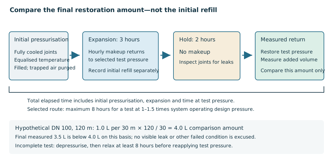
*Figure 19.3. Authored state sequence for the selected HDPE test method. The three-hour expansion phase permits hourly makeup; the following two-hour hold does not. Only the measured addition after that hold is compared with the listed allowance. Initial pressurization is included in the method's total-time limit, although it is shown before the timed phases. [Structured sequence, quantities and size data](assets/C18/c18-hdpe-test-states.json) supplies the companion representation. The diagram specifies no project test pressure or valve line-up.*
*Table 19.1. Final test-phase makeup amounts in the selected method, after its two-hour no-makeup hold. The two length/unit columns are the method's rounded published alternatives, not exact conversions of one another. [Structured cells and scope](assets/C18/c18-hdpe-test-states.json).*
| Pipe size, DN (NPS) | Litres per 30 m | Gallons per 100 ft |
| --- | ---: | ---: |
| 80 (3) | 0.5 | 0.15 |
| 100 (4) | 1.0 | 0.25 |
| 150 (6) | 2.3 | 0.60 |
| 200 (8) | 3.8 | 1.0 |
| 250 (10) | 4.9 | 1.3 |
| 300 (12) | 8.7 | 2.3 |
| 350 (14) | 10.6 | 2.8 |
| 400 (16) | 12.5 | 3.3 |
| 450 (18) | 16.3 | 4.3 |
| 500 (20) | 20.8 | 5.5 |
| 600 (24) | 33.7 | 8.9 |
| 750 (30) | 48.1 | 12.7 |
| 900 (36) | 68.1 | 18.0 |
For a homogeneous length evaluated on one column's basis,
\[
V_{allow}=v_{ref}\frac{L}{L_{ref}}.
\]
Here \(V_{allow}\) is the final makeup comparison amount. \(v_{ref}\) is the table amount for the selected size and reference length. \(L\) is the evaluated pipe length. \(L_{ref}\) is 30 m or 100 ft for the chosen column.
Use the same length unit for both lengths and retain the selected column's volume unit. This proportional calculation explains the length basis. It does not establish a method for mixed sizes, unlisted components or an altered test configuration.
Select one complete unit/length column; the rounded companion entries do not justify additional precision.
Time limits also belong to this route. For a test at one to one-and-a-half times system operating design pressure, total duration must not exceed eight hours. This duration includes initial pressurization, expansion and time at test pressure. That condition supplies a duration limit. It does not itself select a permissible test pressure for an actual assembly.
If leakage, equipment failure or another interruption prevents completion, depressurize. Before applying test pressure again, allow at least eight hours of relaxation. The three- and two-hour phases do not permit indefinite pressurization before or after them.
Other nonmetallic test guides use different hold periods, temperature guidance or manufacturer-selected pressures. Their conditions cannot be assembled into a hybrid by taking a pressure from one, a holding time from another and this makeup table from a third. The HDPE method used for a specified mixed HDPE/steel boundary, the thrust-block-age requirement mentioned above and an RTR alternative each retain their own eligibility and sequence.
Record the chosen test method, actual temperature, pressure, elapsed times, makeup quantities, length/size basis and leakage observations in [the test record](#chapter-c21). This record lets later retesting use the same physical meaning.
## Define cleanliness before selecting the cleaning method
Cleanliness is a required internal condition, not the name of one process. Loose debris can obstruct a burner or damage close-running machinery. Adherent scale can later detach and enter a compressor or oil circuit. Oil, grease, preservatives or cleaning residues can interfere with a sensitive service. A cleaning method is appropriate when it removes the unwanted material without creating an unacceptable new condition in the included materials and equipment.
One useful scoped vocabulary separates four duties:
*Table 19.2. Internal-condition duties under the selected cleaning basis.*
| Duty | Required internal condition under this cleaning basis |
|---|---|
| A | Remove loose non-adherent material and adherent material that could break away in operation |
| B | Remove oil, grease and protective coatings |
| C | Remove adherent rust and mill scale to leave bare metal |
| D | Protect the cleaned surface against rust bloom before startup |
The equipment/material schedule selects the combination and method sequence. Under this particular basis, C and D are performed only when specified by the responsible engineer. The same schedule treats stainless lube/seal-oil piping differently from carbon steel, and its stainless scope includes duplex. These letters are useful locally. They are not universal cleanliness grades or particle-count acceptance categories.
### Match the route to the material and equipment boundary
A material-specific machinery-piping procedure chemically cleans ferritic steel to remove dirt, grease, paint, rust and scale down to base metal. It detergent-flushes austenitic stainless steel to remove dirt and grease. Shop cleaning of flanged/threaded work, in-place cleaning where field welds are required and recleaning of equipment-supplied piping have different access and isolation arrangements. Final oil flushing is expressly outside that procedure. The chemically cleaned spool is one input to the later operating oil system.
The following representative routes preserve that distinction beside a broader equipment-cleaning schedule. They describe the selected method family. They do not authorize one route for every installation.
| Bounded route | Required condition or stage sequence | Interface that controls the choice |
|---|---|---|
| Ferritic machinery-piping chemical route | Flush, degrease, pickle, passivate, dry and protect against rust | Chemical compatibility and stage observations; bearings/seals excluded; later oil flushing separate |
| Austenitic machinery-piping detergent route | Remove dirt/grease by degreasing and flushing | Compatible water/solution and included components; ferritic pickling is not automatically required |
| Carbon-steel lube/seal-oil schedule | Selected debris/oil/scale/protection duties; water flush, alkaline wash, acid/chelant, passivation and protection | Bare-metal/protection duties remain conditional where specified by that schedule |
| Stainless lube/seal-oil schedule, including duplex where stated | Selected debris/oil duties; clean construction, mechanical and compatible solvent cleaning | This schedule's scope differs from the austenitic detergent route; hydrochloric acid excluded |
| Centrifugal/axial-compressor suction schedule | Selected debris/oil duties and mechanical cleaning; compatible inhibitor/oil protection or a nitrogen blanket under this route | Wholly stainless systems are excepted from those preservation measures; temporarily disconnected joints still require blinds, plugs or caps |
| Reciprocating/rotary-compressor suction/interstage schedule | Listed clean-construction/mechanical or chemical sequences, including connected vessels, exchangers and pulsation devices | Specific suction chemical-cleaning duty and material exclusions must remain in the selected instructions |
*Table 19.3. The [structured route comparison](assets/C18/c18-cleaning-routes.json) retains each scope and its qualifications. Letters A–D above remain local internal-condition duties, rather than universal material cleanliness classes.*
A broad matrix can list alternative routes while a specific compressor-suction requirement calls for chemical cleaning. In that case, retain the distinction in the selected instructions.
Neither a table row nor the generic name “cleaning” independently settles the applicable route. Likewise, a stainless base pipe does not establish the material of every valve trim, gasket or instrument in the circulation boundary. The solution must be compatible with every included item, and excluded components must actually be isolated.
A chemical circuit that excludes bearings and seals must retain that bypass. A subsequent manufacturer-defined oil flush can use a different final path through bearings after its initial bypass. Its medium and operating function explain the difference. Combining the two instructions without their boundaries can damage a bearing or leave its operating oil path unverified.
Construction must control weld debris and temporary material before internal access is lost. Mechanical cleaning needs access and debris-removal paths; the chemical route depends on material compatibility and the selected internal-condition duty.
A compressor suction or lube/seal-oil system illustrates the consequence. The required result is not merely a shiny accessible flange. Material that can detach from a hidden pocket must be removed, and the cleaned state preserved through final connection. The extent can include coolers, dampers, bypasses and vessels as specified, while excluding sensitive machinery or internals from a particular cleaning circuit. Burner-fuel lines require unobstructed burner openings after their selected blow/cleaning method. The cleaning diagram should show the actual circulation, bypasses, restrictions, collection points and final acceptance observations.
### Flushing flow and the passage it cleans
A fixed circulation flow produces lower mean velocity in a larger bore; parallel branches can receive less flow than the pump discharge total. Use actual internal diameter and flow in each cleaning path. A selected process-system route specifies a minimum 10 ft/s (3.048 m/s). Pump duty, restrictions and the temporary circuit must support the selected route; velocity alone does not establish cleanliness.
## Cleaning chemistry, observations and preservation
A chemical-cleaning boundary must be compatible with pipe, valve trim, gaskets, instruments and every included component. A carbon-steel line can contain a stainless instrument or chromium-containing trim. Choosing a cleaner solely from the line's base material can damage that item. Bearings and seals are bypassed in a chemical-cleaning procedure that excludes contact with its cleaning solutions. This is distinct from a final lubricating-oil flush whose equipment-specific method can require flow through bearings after an initial bypass. The medium, phase and equipment instructions distinguish the two routes.
High-point vents and low-point drains are needed to fill, circulate and remove the selected solutions. Acid is not introduced into a boundary lacking its required removal path. Direct heating of an acid-filled item can be excluded by the procedure, which instead heats the diluted solution externally. Degreasing, pickling, rinse, passivation and final examination are separately observed so that completion of one stage does not conceal an unfinished subsequent stage.
The cleaning circuit needs leak-tight temporary connections, high-point vents and drains at low points and blanked-end pockets. Degreasing, oxide removal, rinsing, passivation and drying are distinct stages under a complete material-specific procedure. Required sample/endpoint observations determine completion; individual chemicals or endpoint tests cannot be transferred between routes. Collection and disposal capacity belong to the temporary circuit.
Material restrictions govern chemical selection. Under a stated austenitic-material route, hydrochloric acid and other halide-containing acid cleaners are excluded. Acidic alternatives, neutral/alkaline solutions and rinse water have their respective chloride criteria. Duplex is included where the cleaning schedule says so.
Caustic solutions have their own concentration/residue and flushing concerns. Carbon-steel acid-cleaning appendices describe a different material route and must not be transferred to stainless assemblies. Cleaning penetration and temperature limits likewise belong to the selected procedure.
Completion is established by the required observations and tests, which can include visual and tactile examination, stage-completion checks, filters, screens or specified particle measurements. Visual absence of foreign matter and lack of grittiness can be the selected general condition. A machine-specific lubrication duty can require a finer quantitative criterion. Particle-count classes, screen observations and microscopic-size designations are different methods. Their limits cannot be combined by choosing the smallest displayed number. The manufacturer and service basis establish the method and sampled location.
### Keep removal, material loss and moisture criteria distinct
One ferritic/austenitic cleaning basis permits no retained particle larger than 5 mils and limits chemical metal penetration to 0.2 mils. A mil is 0.001 in: the particle length is 0.127 mm (127 μm), while the metal-loss limit is 0.00508 mm (5.08 μm). The first describes remaining debris. The second describes loss of material during cleaning. Neither is a particle-count class or a final machine-oil criterion, and satisfying one does not demonstrate the other. The [structured cleaning quantities](assets/C18/c18-cleaning-quantities.json) preserve these different duties and conversions.
Flushing velocity also belongs to a stage. The process-flushing example above uses a 10 ft/s condition. A particular ammoniated-citric-acid circulation/rinse route specifies 2 ft/s. Its chemical concentration, pH, temperature and oxide-removal observations act with that flow condition.
The complete cleaning procedure governs chemistry, stage endpoints and material compatibility. The circulation velocity is a stage condition, not a substitute for the required internal-condition result.
Temperature quantities differ as well. A stainless test-water drying route specifies air below 140°F, while a cleaning restriction limits austenitic equipment metal to 125°F. Gas temperature and attained metal temperature are different observations. A ferritic cleaning route instead uses 160–180°F nitrogen to achieve a stated −40°F dewpoint immediately after draining. Another carbon-steel route uses 150–170°F drying gas.
For drying criteria, retain the selected procedure, material and measured moisture basis with the values. Do not combine the values into one band.
Dewpoint interpretation still requires its measurement pressure/reference and representative location.
The cleaning state can include disassembled, water-filled piping with temporary supports. A particular procedure's 3/8 in deflection limit belongs to that state. It does not replace an operating span's sag criterion. Flow reach, drainability, chemical compatibility and support adequacy must survive the temporary circulation arrangement together.
Preservation closures depend on exposure duration and material. One procedure distinguishes a seven-day erection horizon: specified film at flange ends and line-class plugs for short exposure, secured metal protectors with gaskets and closures for longer exposure. These contamination barriers have no inferred pressure-test rating. Covers remain until permanent connection, with dry attachment/storage and cleaned-state identification.
Compatible rust preventive follows ferritic drying, with excess drained from pockets. In the particular centrifugal/axial-compressor suction route above, compatible vapor-phase inhibitor/rust-preventive protection or a nitrogen blanket are alternatives. Its lubricant-based measure excludes non-lubricated and refrigeration compressors. Under that route, a system constructed entirely of stainless steel does not require those preservation measures.
Temporarily disconnected joints still require blinds, plugs or caps against contamination. That bounded exception does not exempt stainless systems from other selected drying, cleanliness or preservation duties. Changing the exposure period or opening the cleaned joint reopens the preservation decision.
Draining and drying then remove a further contaminant: the cleaning or test medium itself. The fluid can remain in dead legs, low points, instrument connections and cavities. A required dewpoint is a measured moisture condition under its method, not a name for a chosen gas supply. Drying temperatures and gases must be suitable for the material, equipment and service. Cleaned ferritic piping may require compatible rust prevention, while stainless or a non-lubricated compressor can have a different protection duty. Excess preservative in a pocket is itself a condition to remove where required.
Protective covers, plugs, blinds or a prescribed inert blanket preserve the accepted state until final connection. Their duration and integrity affect whether the earlier result remains valid. Opening a cleaned joint, transporting a module, welding a field connection or leaving a system wet can reopen cleanliness or preservation evidence. A final cleaning as close as practicable to first machinery operation can reduce this exposure under the selected equipment route. [Special-service cleanliness](#chapter-c13) determines any additional service-specific condition before introduction of the fluid.
## Restore the service configuration and demonstrate readiness
Before removing test items or opening joints, depressurize and drain by the prescribed sequence.
Venting prevents trapped pressure and can prevent an unintended vacuum during drainage. Differential-pressure limits remain applicable while releasing connected equipment. The final pressure reading at one gauge does not establish that an isolated pocket is depressurized. Its local boundary and bleed arrangement must be known.
Reinstatement removes test blinds, temporary spools and other items designated for removal. It returns identified instruments and internals to their correct locations. It remakes the affected joints by their assembly method. A restored flange has a new joint-making event even though the adjacent spool passed its earlier test. The required subsequent leak check or examination follows that changed condition. Test records should distinguish the boundary tested from the boundary finally restored.
Restore the defined support state: remove or retain spring locks, shipping ties and temporary supports according to the selected transition; confirm cold settings, contact, guide gaps, movement freedom and expansion-joint preset. Releasing a restraint differs from removing a permanent support. See [support states](#chapter-c10).
*Table 19.4. Readiness evidence and changes that reopen it.*
| Readiness question | Evidence to preserve | Change that can reopen it |
|---|---|---|
| Is the intended arrangement installed? | Walkdown, accepted dimensional/configuration changes and component identity | Substitution, moved equipment, altered branch or valve arrangement |
| Are local joints in their required condition? | Applicable welding/bonding, treatment and examination records | Repair, added field joint or later thermal work |
| Was the required boundary tested? | Marked boundary, medium, pressure/temperature, gauge and observation records | A new joint, changed isolation or different included component |
| Is the internal condition suitable? | Cleaning stage and final acceptance results, dryness and compatible preservation | Opening, transport damage, residues or loss of protective condition |
| Is the service configuration restored? | Removed temporary-item list, returned internals/instruments, remade-joint and support-release checks | An incomplete replacement or retained shipping restraint |
| Can operation begin under its intended conditions? | Outstanding-work disposition and service-specific release checks | Unresolved leak, missing equipment condition or changed service |
The [structured readiness tables](assets/C18/c18-readiness-tables.json) retain the same handover questions and internal-condition duties. The table is an authored handover method, not a universal certificate form. It keeps different warrants connected to the actual line and its transitions. A successful pressure test does not permit closure of an unresolved cleanliness or configuration question. A sensitive leak result does not establish every operating load case. A valid shop result can be reused when its scope and unchanged condition are demonstrated, while a changed joint or boundary receives its affected checks.
The test record identifies its actual boundary/configuration, medium, pressure, temperature, duration, gauges, protection, observations, repairs and retests. Cleaning and reinstatement records preserve their own conditions. [Engineering records](#chapter-c21) makes that evidence usable for later inspection and [maintenance, repair and change](#chapter-c20). Readiness is the established connection between those results and the configuration that will enter service. Unresolved work and genuinely missing information are made visible to the people responsible for release.
# Chapter 20 — Operating integrity, inspection and maintenance
## Begin with the installed system and its present duty
The installed material, wall, support contact, joints and protective functions can differ from the original design/test state. Replacing a valve changes concentrated weight; changing temperature changes movement; lower gas flow can move water and deposits. These changes can invalidate an earlier assessment without changing the line's identity.
Measured condition needs its physical reference: thickness location/method, vibration point and operating/amplitude convention, hose identity and new-length baseline, or the actual protective-function boundary. [Repair and modification](#chapter-c20) addresses the resulting changed configuration.
## Ask what the observation can establish
A visible leak establishes local containment loss, not the surrounding wall or temporary-enclosure life. No leakage does not exclude cracking. Local coupons, thickness points and vibration measurements need coverage of the controlling mechanism: average thickness can conceal pitting, and small motion at a highly stressed attachment can govern over larger span motion.
Inspection access constrains routing and assembly. The selected tool must enter the pipe; required surfaces must be reachable and preparable; covered joints need a feasible examination route. See [buried and offshore geometry](#chapter-c11).
*Table 20.1. Observation evidence and consequential limits.*
| Observation or test | Useful evidence | Consequential limit |
| --- | --- | --- |
| Local thickness measurement | Wall at the measured location under the method's conditions | May miss isolated attack elsewhere; location/history matter |
| Corrosion coupon or recovered pig debris | Local exposure/attack or qualitative evidence of material removed | Does not prove the full route is undamaged or give a route-wide rate |
| Vibration displacement measurement | Actual motion at the measured point and operating state | Needs stress/geometry and state coverage; magnitude alone does not establish fatigue acceptability |
| Hose pressure and elongation assessment | Containment and measured length response under the specified test | Does not excuse inner-tube, reinforcement, vacuum or handling damage |
| Electrical continuity check on hose | A conductive path under the measured condition | Water can supply a false path; bonding purpose and construction matter |
| Protective-function test | The defined action within the tested boundary | A partial component test does not demonstrate the entire detection/logic/final-action path |
## Observe wet sour corrosion where the changing flow puts water
Wet sour gas can produce markedly different corrosion behavior in lines carrying similar chemistry because flow changes where water, deposits and inhibitor contact the wall. A production decline can move an annular/mist condition toward stratified or slug flow. Water can settle at the bottom, solids can interfere with protective scale and inhibitor reach, and the resulting attack can be highly localised. A steady-operation program designed for the previous flow state may no longer address the controlling mechanism.
Coupons can miss isolated pitting; monitoring/inspection locations must cover expected water residence, deposits, turbulence, elevation and temperature changes. Fluid analyses, flow and actual inhibitor delivery distinguish a nominal concentration target from availability at the wet wall.
Inhibitor residual is another piece of evidence, not a substitute for understanding where the relevant phase goes. A chemical that partitions appropriately under mixed flow may reach the wet surface differently under stratification. Solids can adsorb inhibitor or shield the wall. High salinity, low pH or altered production fluids can also change performance.
The inhibitor's selected operating envelope and actual wet-wall coverage govern mitigation; see [corrosion control](#chapter-c15). A faster sampling cadence cannot correct a point that misses the controlling pit or crack.
## Reassess mitigation through startup, shut-in and restart
Non-steady states can change the corrosion mechanism. Initial well cleanup can bring solids, salinity and low pH. Mill scale can consume inhibitor as it converts and loosens. Prolonged blanketing can change protective scales, and opening a line to moist air can change the surface that later sees wet sour flow. Methanol addition can affect both chemistry and inhibitor behavior, including the consequences of oxygen introduced with it.
The mitigation arrangement must remain effective through startup, stimulation, shut-in and restart as fluids and exposed surfaces change.
Opening sour equipment also creates exposure hazards distinct from corrosion rate. Iron-sulfide deposits can heat on air exposure. Sensitised material can have another moisture/oxygen cracking concern. [Sour-service intervention](#chapter-c13) keeps those mechanisms and local precautions separate. Cleaning, preservation or gas-free evidence for one hazard does not establish every material and atmosphere condition required for entry or restart.
An outage offers access to a hidden location but also changes support, contents and contact conditions. Drainage can leave deposits in another location. Removing insulation can expose the pipe or damage its protection. A temporary spool or a newly welded connection can change material or stress state.
## Investigate vibration in the operating states that excite it
A vibration report should identify where motion occurs, the connected span/branch/components, support/contact condition and the operating event. Flow, pressure, valve position, pump/compressor condition and a transient can change excitation or response. A spot measurement in an easy-to-observe condition can miss the maximum condition. Measurements over a well-defined operating envelope establish a different evidential basis from a single observation.
Cyclic stress is often highest where motion is restrained. Large displacement in a flexible portion of a span may coexist with modest local stress. Small motion close to an anchor or branch root can impose a high alternating stress. Measure the actual response and evaluate it with the geometry, attachment and loading model appropriate to the system.
Amplitude conventions (peak, peak-to-peak or other) must match the selected limit.
The adopted fatigue method also matters. One operating-vibration procedure distinguishes a system monitored over its full expected range from cases with only spot observations. For the latter, it uses a separate factor on its selected endurance-curve basis. For a project adopting that particular steel-weld endurance-curve convention, its spot-observation case divides the selected design endurance value by 2.0. This factor cannot correct an unsuitable measurement point or an unobserved operating state, and is not a universal multiplier for every displacement or material. [Dynamic and fatigue evaluation](#chapter-c09) supplies the analysis.
Corroded/loosened supports change response and load paths. Adding a guide can suppress visible vibration while blocking thermal movement and increasing equipment loads. A changed transient, valve or process can initiate late-life fatigue; restoring a failed support does not remove existing pipe/attachment fatigue damage. See [support and restraint function](#chapter-c10).
## Diagnose a leaking joint before selecting its intervention
Leak paths can arise from assembly/alignment, sealing-surface damage, gasket/packing deterioration, vibration, corrosion or changed duty. The actual medium, pressure/temperature, location and components determine intervention eligibility.
A clamp-type hub connector provides a useful example. If a properly tightened joint leaks, additional or excessive bolt tightening does not necessarily restore alignment or a damaged seal. Field observations for one such connector basis require opening the joint to determine the cause. That observation is a locally applicable repair/inspection route, not a universal instruction to tighten or dismantle every leaking joint while pressurized.
Opening requires the service-specific isolation and work configuration.
For any contemplated tightening in service, torque or bolt-load instructions must be established for the actual joint, condition and intervention. A torque value from initial assembly is not automatically a suitable live-leak remedy. A visible seal-ring scratch also needs assessment before repair or reuse. [Joint behavior](#chapter-c03) explains the component mechanism; [Repair](#chapter-c20) explains the evaluated intervention and changed containment.
Valve-stem or bonnet leakage can affect containment and exposure without creating an obvious pipe-wall defect. Packing/lubrication, seal design and the chosen service requirements matter. A bellows or injectable seal feature creates its own maintenance and failure modes. It does not make inspection unnecessary.
A temporary repair then becomes another item to monitor. Its weight, newly wetted components, temperature envelope, deterioration beneath it and planned removal matter. Reinjection or retorque is a reassessment event under the applicable repair basis, not merely repetition of the original action. The diagnosis and continuing condition evidence belong here. The enclosure, wrap or online connection design belongs in [repair and modification](#chapter-c20).
## Treat flexible hose as an identified operating assembly
A hose combines an inner tube or lining, reinforcement/carcass, cover and end fittings. Its flexibility comes from its construction, and its pressure, temperature, chemical and vacuum duties must fit that construction. A flexible route still has limits on bend, torsion, tension, support and handling. Calling it a hose does not permit it to absorb arbitrary equipment or vessel movement.
Cargo and submarine hose, steam hose, LPG hose and other specialty assemblies have different bases. The methods below illustrate a particular cargo/submarine in-service inspection arrangement, including its 275-psi-grade context. They are not general requirements for every hose family.
A rated working pressure is not burst pressure or test pressure. New-hose burst margin cannot be credited as a permitted operating excess, and aging/damage can reduce that margin.
Maximum available pressure includes pump, head and surge with the selected protection, rather than normal transfer pressure alone.
Flange/coupling temperature ratings and liner chemical limits are part of the same assembly envelope.
Dragging/rolling, sharp end-fitting bends and concentrated lifting can damage the assembly.
Support the hose so vessel motion and tide changes do not kink or abrade it. Adjust the actual supported curve as the vessel moves. Rollers, saddles and chafing protection serve different locations and loads. Pressure pulsation and contact with a hot surface can add another damage mechanism. An operating hose string needs enough length and support for the actual movement, not only an initial dockside fit.
External inspection looks for cover damage, flattening, ridges, bulges, corrosion and end-fitting condition. Circumferential ridges can indicate a broken helix capable of damaging the inner tube or reinforcement. Internal inspection looks for looseness, tears, bulges and fitting cracks. A harmless manufacturing lip in one construction is not a loose lining in another. Cutting a lining feature can destroy a particular barrier layer.
### Compare measured length response with a defined new-hose baseline
The adopted cargo/submarine route measures flange-to-flange length in defined pressure states. The original benchmark \(L_o\) is measured at 10 psi after raising the hose to rated working pressure, releasing to zero and holding the 10-psi state for five minutes, unless that original benchmark is already recorded. Test length \(L_t\) is measured during the 15-minute hold at 1.5 times rated working pressure. After the 25-psi low-pressure leak check, the hose returns to 10 psi for a 15-minute rest before measuring permanent length \(L_p\). Support/extension and air removal follow the complete selected test method; see [testing](#chapter-c18).
The two percentages are
\[
E_t=100\frac{L_t-L_o}{L_o},\qquad
E_p=100\frac{L_p-L_o}{L_o}.
\]
In these equations, all lengths use the same unit and measurement convention. \(E_t\) and \(E_p\) are percent.
Periodic results use the original new-hose reference and recorded new-hose test/permanent elongations; resetting the baseline to an aged length conceals permanent extension.
Its limits use the greater of the new-hose value plus four percentage points or twice that value. Thus, for \(E_{t,new}\) expressed as a percent number,
\[
E_{t,limit}=\max(E_{t,new}+4,\,2E_{t,new}),
\]
An analogous expression applies to \(E_p\). The added 4 is on the same percent-number scale. It is not a 4% relative multiplication of the new value.
The greater-value rule belongs to this procedure; the percent-number addition is not relative multiplication. Hypothetical new/current arithmetic remains in the structured companion.
Leaks, inner-tube damage, broken reinforcement, fitting condition, vacuum performance and other applicable criteria still matter.
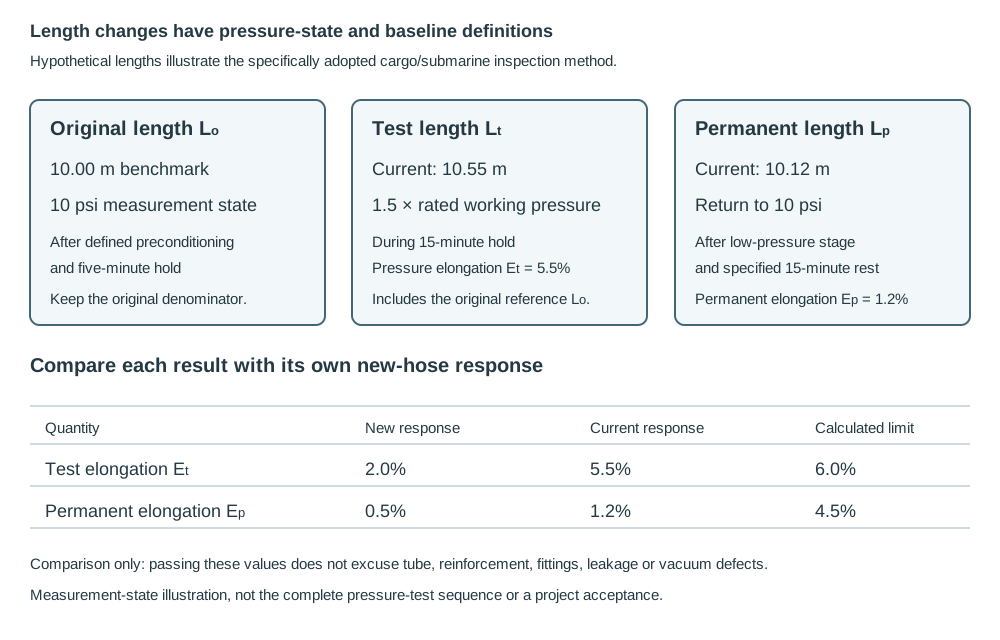
*Figure 20.1. An authored measurement-state illustration using hypothetical current lengths. Original, test-pressure and permanent lengths have different definitions; the original new-hose benchmark remains the denominator. The panels do not supply the complete pressure-test procedure. [Structured teaching calculations](assets/C19/c19-methods.json) retain the new/current values, units, comparison rules and assumptions.*
The 1.5-times-working-pressure inspection route is distinct from manufacture/qualification tests and actual component limits.
## Give each hose test its own purpose and disposition
Hydrostatic inspection observes leakage, bulges, ridges, fitting movement and measured length response under the specified condition. A low-pressure stage can reveal a fitting leak not apparent at the preceding pressure. Vacuum examination addresses inner-tube separation, flattening and kinking. Electrical continuity addresses the conductive path needed for a particular assembly purpose. These are different warrants.
Water inside or outside the hose can provide a conductive path and conceal a broken intended bond.
The selected continuity observation uses an empty hose as dry as practicable.
In a submarine assembly, internal bonding can be part of cathodic-protection continuity. It is not automatically required for static protection, and the consequence of a loss depends on the assembly and whether it signals broken reinforcement. A different position in a string is a separate evaluated disposition, not permission to ignore an internal helix break.
Construction changes the visible damage criteria. A solid-wire-reinforced hose with a severe local kink is evaluated differently from a helix-free or kink-tolerant construction under its vacuum test. The adopted procedure gives separate criteria for these families.
A single flattening criterion cannot apply to all hose constructions, and an intact cover does not establish sound reinforcement.
External-cover-only damage in an otherwise acceptable hose can be repairable under the applicable method, followed by full required testing. Inner-tube tears or looseness, cracked fittings, broken strength reinforcement and pressure leaks lead to a different disposition. Mark and remove condemned assemblies so they cannot be confused with serviceable stock. A destructive evaluation of a retired hose can provide information about degradation. It is not a way to return that item to service.
For a cargo/submarine inspection program specifically adopting the following maximum intervals, keep the type and accessible location distinct:
*Table 20.2. Conditional cargo and submarine hose inspection intervals.*
| Inspection under this program | Cargo hose | Submarine hose that can be lifted above water | Submarine hose at depth |
| --- | ---: | ---: | ---: |
| External | 6 months | 6 months | 12 months |
| Internal | 6 months | 12 months | 12 months |
| Vacuum and hydrostatic | 12 months | 12 months | 12 months |
*These are local program maxima, not universal intervals for every hose. The [structured inspection table](assets/C19/c19-inspection-methods.json) preserves their construction/service and access scope.*
That program also normally requires hydrostatic assessment before reuse when a hose has been out of service and untested for more than six months. Retained-pressure/chemical/handling history still matters. Unusual stress, pressure, storm or handling damage calls for the required additional assessment before reuse. A calendar maximum is not a promise that a damaged hose remains suitable until its date, and an old manufacture test is not current-condition evidence.
Storage and cleaning preserve another state. The selected drainage/aeration/preservation method depends on the product and hose construction. Indefinite storage differs from frequent duty. Sun, ozone, retained product and a damaged cover affect the stored assembly.
## Keep maintenance access and the load path available
Inspection and repair require a physical work arrangement. A filter needs room to remove its element without dropping trapped material downstream. A heavy valve needs a maintained weight path for the remaining pipe when it is disconnected. Insulation/coating access can require removable covers or a planned restoration of the barrier. An instrument bridle needs safe isolation and access to the measurement element.
Spring settings/locks, resting-shoe contact, guide clearance, bracket corrosion and movement relative to neighboring steel define the maintenance load state.
A removed or failed support can change the sustained load path before a visible pipe leak appears. Added repair weight, a seized slide or an unintended restraint can alter equipment reactions. [Support assessment](#chapter-c10) supplies the mechanical decision. The maintenance configuration must preserve or re-establish the relevant contacts and freedoms.
Coatings and insulation can hide or create deterioration. A support crevice retaining seawater and an insulated cold surface retaining moisture have different exposure and access conditions.
The arrangement needs access for required surface preparation, recoating and inspection.
Opening the protection to inspect also creates a restoration task. Leaving a broken vapor barrier or poorly sealed penetration can recreate the mechanism after an apparently successful wall examination.
Nonmetallic and lined systems need their own condition evidence. Metal-wall adequacy does not establish retained liner integrity. A permeated-gas annulus can affect depressurization behavior. Reinforced resin or polymer joints cannot be assessed or repaired simply by importing a metallic weld/torque method.
[Material variants](#chapter-c02), [installation](#chapter-c17) and [repair](#chapter-c20) carry those detailed interfaces.
Offshore access adds restricted space, marine exposure and limited lifting/support services. A riser or under-deck line may require diver or remotely operated inspection access fixed by its original geometry. A removable spool can enable equipment withdrawal, but introduces joints and a changed load path.
## Match material-condition evidence to the system that can be damaged
A metal wall, an internal lining and a reinforced-resin laminate perform different roles. A thickness reading on the steel may establish part of its containment section while leaving a damaged liner unresolved. Permeated gas retained behind a lining can create another differential-pressure state on depressurization.
The annular vent/pressure arrangement and liner condition govern that differential state; an unlined-steel corrosion allowance does not establish liner adequacy.
The maintenance consequence depends on construction. Under particular lined-system repair methods, damage to a plastic or resin liner can require replacement or relining of a complete joint/section. Under those methods, local cement-liner end damage may permit a selected patch. This distinction identifies the evidence and access needed for the proposed intervention; [repair methods](#chapter-c20) owns its actual eligibility and execution. A small visible defect can therefore demand substantially different preparation in two systems with the same steel outside diameter.
Reinforced thermosetting resin needs laminate/reinforcement condition evidence as well as surface observations.
Crazing, dry reinforcement, fracture/interlaminar separation and cut roving are different observations from a shallow scratch that does not expose fibers. Manufacturing visible-defect descriptions help identify those features. Their purchase-acceptance table is not automatically an in-service discard rule. For a critical high-pressure FRP application, a selected acoustic-emission assessment can be considered under its own method.
This does not make it mandatory for every resin line or an unrestricted substitute for other quality and condition evidence.
Thermoplastic fusion joints and resin-bonded joints also have different qualification, damage and repair routes. A repair sleeve/clamp acceptable under a particular low-pressure FRP method is not thereby a general pressure-pipe repair for HDPE. The relevant HDPE repair basis favors replacing/fusing the damaged section.
Cleaning and inspection can themselves damage a nonmetallic internal surface. Particular HDPE/FRP guidance permits smooth polymer pigs and excludes scraper pigs for those products.
[Material behavior](#chapter-c02), [inspection-tool geometry](#chapter-c11) and [cleaning](#chapter-c18) together establish whether the chosen access and action preserve the system.
## Demonstrate protective and utility function as well as containment
A protective valve's body integrity does not establish the required detection, logic, utility and final-action path. Temporary bypass/isolation can disable that function while hardware remains installed. See [protective systems](#chapter-c08) and [measurement/control](#chapter-c22) for the actual functional boundary.
Utility observations should also follow their required function. Air pressure alone does not prove dryness or remote reserve. Heater circulation alone does not prove the fluid is uncontaminated. A hot condensate discharge does not distinguish every trap failure or low-differential condition.
Consumer quality, pressure and temperature requirements remain those of the selected [utility architecture](#chapter-c12).
Maintenance of a shared filter, compressor or return header can affect several consumers at once.
Service-specific restoration remains local. Oxygen work must retain clean components and the stated separation/atmosphere distinction. A chlorine water test must be followed by its cleaning/drying basis. Sour equipment opening must address deposit and material exposures. Cold liquefied-service work must preserve temperature and pressure-protection assumptions.
The general readiness method in [verification and restoration](#chapter-c18) connects these tasks, while [service mechanisms](#chapter-c13) explains why their conditions differ.
# Chapter 21 — Repair, hot tapping and modification
## Decide what the intervention is intended to restore
A repair can restore the original design, establish a permanent change or contain a defect for a bounded period. Enclosing a leaking joint leaves its damaged components in place; replacing the joint can remove them. An online branch adds a pressure boundary and load path while the run remains live.
Shutdown/replacement, a qualified permanent repair, redesign, a temporary enclosure/wrap and justified online work have different remaining-wall, deterioration, containment, load and inspection requirements. Temporary leak stoppage does not establish permanent suitability. [Operating integrity](#chapter-c19) addresses the actual damage observations.
## Make the damaged component and planned life part of the design
A thin region, a growing crack, a damaged joint and an unsuitable material have different repair problems. Define the remaining section, location, extent and geometry with the applicable examination. Determine whether the defect is local or indicates a larger affected region. An enclosure placed over one hole can leave surrounding internal corrosion active. A pressure test at the end of work does not establish the future rate or crack-growth behavior.
External and internal deterioration also change the choices. Improving external protection can remove part of an exposure mechanism. Enclosing an internally corroding line does not remove its corrosive contents. If internal loss continues to a through-wall condition, the repair can then contact process fluid it did not initially see. Its material and sealing basis must cover that credible state and its condition must remain assessable.
Repair life depends on operating/startup/shutdown duty, continuing deterioration, monitoring capability and the required permanent end disposition. Changed duty, unexpected deterioration or rework can require removal before a planned outage.
Fitness-for-service or crack-growth assessment can support particular decisions, but the present account does not supply a complete general method for them. A wall-loss budget or a stopped leak cannot establish fitness by itself. Preserve the required assessment and actual unresolved inputs where they affect eligibility, while continuing the supported evaluation of alternatives, exposure, loading and verification.
## Treat an enclosure as a new containment and contact arrangement
A clamp or welded leak box encloses a leak region. Its annulus and the components inside can become exposed to the service fluid. Wrapping or peening around a flange can have the same exposure consequence even when no separate box is visible. Bolting that originally operated in air can now be wetted by steam, hydrogen or another medium. The original joint's material selection does not automatically cover that new contact.
Under an adopted temporary-enclosure method, assess those newly exposed parts. Either establish their suitability, replace/protect them by an applicable means or choose another repair. A strongback can provide a separate holding function where the original fasteners cannot be relied upon in the new exposure. It must actually carry the required separating load through its attachments. A device that merely surrounds the leak is not automatically such a load path.
In this steam-enclosure example, originally dry B7 or B16 studs can face stress corrosion cracking after steam contact. Leakage capture and joint retention are therefore separate questions.
Added clamp, strongback, sealant and retained-fluid weight must reach a suitable support. A locally thin line or a heavily loaded nozzle may not carry that addition acceptably. Establish the actual supporting section and the affected span/equipment reactions before installing the repair. [Mechanical evaluation](#chapter-c09) and [supports](#chapter-c10) explain the broader load method. The repaired configuration supplies the changed mass and attachment.

*Figure 21.1. An authored function schematic for an enclosed leaking joint. The repair can expose the original bolting to fluid and adds weight. Any selected strongback provides a separately designed holding path. The diagram supplies neither a clamp geometry nor a qualified repair detail. [Structured enclosure data](assets/C20/c20-enclosure-functions.json) records the assumed contact change and required functions.*
### Reassess the movement function when a joint is enclosed
An enclosure over an expansion, slip or ball joint changes a component selected to accommodate motion. Its added weight is only one question. The enclosure, injection material, contact or attachment can alter the motion available to the joint and the loads transmitted into adjoining pipe. Stopping the leak does not establish that the original movement function remains available.
Under the specifically adopted enclosure method, installation over such a joint requires load analysis with the enclosure installed. The analysis covers the system, anchors and component nozzles. Thermal-induced movement under **both operating and shutdown conditions** is part of that analysis. A hot-state reaction check alone can miss contraction, changed contact or a different restraint on shutdown. The [structured enclosure assessment](assets/C20/c20-enclosure-assessment.json) retains these distinct inputs and verification questions.
Compare the actual joint's intended movement and load path with the proposed repaired configuration. Establish joint travel/rotation, contact and clearance, enclosure attachment, the relevant pipe/support state, temperatures and terminal conditions. The assessment determines what motion is retained, what loads are transferred and whether a different repair or operating restriction is required. It does not assume that every clamp is rigid or assign a stiffness that the repair construction has not established. [Mechanical evaluation](#chapter-c09) and [restraints](#chapter-c10) supply the broader modeling and reaction methods. The enclosure supplies the actual changed configuration to evaluate.
### Distinguish leak capture from control of crack growth
For a project adopting one temporary-enclosure procedure, a cracked component is ineligible unless one of its stated engineering conditions is established. These include:
- Eliminating or mitigating crack formation/propagation over the repair life
- An applicable fitness assessment establishing acceptable growth confined within the enclosure boundary
- A defined crack condition with an enclosure designed for full circumferential separation
- Full encapsulation of the specified cracked vent/drain case
These are alternatives with different evidence and load requirements, not a common permission inferred from the presence of a clamp.
A sealing enclosure can remain leak-tight while an unassessed crack propagates beyond it or the original component separates. The chosen function therefore has to match the damage scenario. If complete separation is part of the assessment, pressure-generated axial force and retention become design questions in addition to seal pressure. If growth is controlled by mitigation, the continued availability of that mitigation belongs to the repair's operating basis.
Sealant injection introduces another loading and interaction. Annulus pressure and uneven injection can damage the weakened original component. A void-filled enclosure and a perimeter-seal arrangement distribute injection differently. Sealant entering the process can block strainers, small connections or meter passages, interfere with control valves or reduce a relief path's capacity. Evaluate both the local load and the downstream destination/function before choosing the injection detail.
Temperature selection must cover the repair's credible duty. A standby-pump warm-up line can be cool when clamped and much hotter when the pump is used. A sealant selected only for installation temperature can volatilize or lose its sealing behavior later. Keeping a high-temperature sealant warm with temporary tracing/insulation can introduce other exposure and corrosion effects. That is another evaluated configuration, not an automatic cure. Re-injection or retorque also reopens the repair assessment under the applicable procedure.
### Inspect the existing repair before repeating its intervention
Reinjection and retightening act on an enclosure that already has a service history. A renewed leak can indicate changed sealant condition, bolt loading, corrosion, joint movement or damage. It is not evidence that the original assessment remains valid. Rework should begin with the observed defect and repair condition, then determine the selected method and whether the original life and permanent-removal plan still apply.
One adopted enclosure procedure requires inspection of the enclosure, bolting and adjacent components before every reinjection or retightening. It additionally requires a complete new assessment before the fourth **reinjection**; retightening is not counted as reinjection. The [structured history companion](assets/C20/c20-enclosure-assessment.json) retains that local trigger and examples.
Changed temperature, continued internal loss, changed joint freedom or rework can invalidate containment, material-contact, crack-growth and load assumptions before that count. The repaired region must remain inspectable through its evaluated life.
## Keep repair methods with their material and defect scope
A composite wrap can reinforce or seal a specified defect only within its qualified material, bond, service and loading basis. A procedure can distinguish a non-leaking external repair from a wrap over an active leak. Under one specifically adopted temporary-repair basis, non-leaking external wraps have no stated pressure-class exclusion. Leaking defects are restricted to Class 150 service and treated as temporary. They require permanent repair at the next turnaround under that procedure. Their evaluated technical life, monitoring and intervention triggers can require earlier action.
That eligibility is local to the adopted method. Nominal class is not the actual operating pressure, and it does not prove compatibility or strength of a particular wrap.
The medium, temperature, steam-out, fire exposure, ultraviolet protection and deterioration beneath the repair can reverse the selection. A resin/bond that works in ordinary duty can be unsuitable in a later high-temperature state. Plan how the affected wall/defect will be monitored with the wrap installed, and what observation requires removal or replacement. Historical ASME PCC-2 and ISO 24817 references identify relevant repair routes, but do not by themselves establish a current qualified design for an application.
Nonmetallic pressure pipe and lined systems require different repair alternatives. Particular HDPE guidance favors cutting out and fusion-replacing a damaged section rather than general compression sleeves, clamps or patches. Particular FRP methods can allow a sleeve or bonded repair for a minor low-pressure leak or as a temporary higher-pressure intervention. Severe damage requires section replacement. Bond preparation, compatibility, cure and examination must belong to the actual resin system. A metallic clamp precedent is insufficient.
A liner also changes what is repaired. Damaged plastic/resin-lined steel can require replacement or relining of a complete section/joint. Cement-liner end damage may have a selected patch route, while another damaged section requires a differently prepared replacement.
The steel wall and lining perform different functions. A sound metal pressure boundary does not establish liner continuity. Access sufficient to examine a local liner patch can be unavailable in a smaller bore. [Material systems](#chapter-c02), [installation](#chapter-c17) and [verification](#chapter-c18) supply their detailed interfaces.
## Justify online welding and hot tapping for the actual case
Hot tapping installs and opens a connection through a pressurized boundary. Welding that attachment while the medium remains inside creates a thermal/material/pressure problem before the cutter ever enters the line. The activity is justified only when the selected online method is technically feasible and offers a clear advantage over shutdown or another alternative. Continuity may be essential, or an outage may create different safety/environmental consequences. Neither consideration demonstrates feasibility without the actual pipe, fluid and equipment conditions.
Establish the run-pipe material and history, measured wall/defect condition, pressure/temperature/flow range, deposit state and intended branch. Include the welding process, consumables and qualified procedure, drilling-machine capability, valve/cutter clearance, connection loads and protective arrangement. The work must remain within those conditions as it proceeds. A drawing prepared for one scheduled operating rate is inadequate if routine plant action can interrupt flow or change pressure during welding.
## Select the governing restriction basis before using its numbers
The restrictions here illustrate specifically adopted procedures. They do not authorize hot work on every service that satisfies a single thickness or velocity. One hot-tap method covers carbon, carbon-manganese and selected high-strength low-alloy steels. Its scope examples run from ISO 3183 L245 to L485 or API 5L B to X70. Its stated experience is limited to L450/X65, so higher-grade procedures require specific attention within that adopted basis.
Other materials require a separately established welding/material procedure. Material grade, weldability, toughness, sour-service condition and prior heat treatment remain part of the choice.
For a narrowly stated blow-out screening condition within that method, measured minimum wall is at least 5 mm under these conditions:
- Yield strength is not above 450 N/mm².
- Operating temperature is not above 350°C.
- Hoop stress is not above 72% of specified minimum yield strength.
This is a coupled condition, not a universal 5-mm hot-tap entitlement. Product chemical stability can require a much lower temperature. The material's allowable operating-temperature envelope has separate exclusions in that procedure. These include maximum allowable temperature above 370°C and minimum allowable temperature below −20°C. The band between −20°C and 0°C needs additional toughness attention. Those envelope limits must not be confused with the hot local wall temperature generated by welding.
A second adopted practice gives a ¼-in minimum wall unless its responsible engineering review accepts a specifically evaluated lower thickness. That value is 6.35 mm, but choosing the larger number does not reconcile the two methods. Their other material, process and qualification conditions still apply. The first method also distinguishes measured actual wall from nominal thickness and reduced wall during welding. The relevant examination must establish the required quantity at the chosen location.
Welding on lined, clad or internally coated pipe is excluded under the first method, and the second excludes its specified jacketed/clad/lined applications. Postweld-heat-treatment requirements need explicit feasibility evaluation. An online attachment must not quietly replace the metallurgical condition that made the original item acceptable. [Joining and heat treatment](#chapter-c16) explains those mechanisms and qualifications.
Fluids must remain stable under welding heat and the air/contact conditions introduced by perforation. An apparently ordinary hydrocarbon can have a decomposition or reaction concern at a local welding hot spot. Oxygen or compressed air with hydrocarbon contamination can create an ignition condition. Toxic media, hydrogen conditions, vacuum and pyrophoric deposits create other hazards. Under one adopted method, its listed hazardous fluids/conditions require positive evidence before welding/hot tapping may proceed. The listing is indicative rather than exhaustive.
Another practice has its own prohibitions and evaluation requirements. A permission or exception in one is not transferred to the other.
Hydrogen illustrates the difference in scope. A temporary-leak-repair practice prohibits live drill-and-tap on its Class 1500 hydrogen systems. A hot-tap procedure separately identifies a hydrogen partial-pressure condition requiring demonstrated safe application. A pressure class, total pressure, partial-pressure criterion and dissolved hydrogen history are different inputs. Do not convert them into one averaged or presumed-conservative permission. [Service mechanisms](#chapter-c13) supplies the local hazard context.
### Use composition as an input to the cooling and welding assessment
Material grade, chemical composition and thermal history are different inputs. A carbon-equivalent calculation weights selected alloy elements to organize a steel's welding assessment. It does not measure hardness or certify weldability. One online-welding procedure uses:
\[
CE=C+\frac{Mn}{6}+\frac{Cu+Ni}{15}+\frac{Cr+Mo+V}{5},
\]
In this equation, each element symbol is its numerical composition percentage on the identified material-analysis basis. Enter 0.15 for a reported 0.15%, not the fraction 0.0015. The result retains that percentage-based numerical convention. The [structured composition method](assets/C20/c20-material-welding-inputs.json) defines the inputs and the procedure's limitations.
The stated procedure treats CE up to 0.4 as a guideline; above it, metallurgical review considers cooling rate and the specific hot-tap WPS. A result below 0.4 does not establish material condition, fluid compatibility, penetration, interpass temperature or delayed-cracking resistance.
Preheat also depends on composition and weld thickness within the actual qualified procedure. [Welding qualification](#chapter-c16) supplies the material/process/examination relationship. The live contents supply another heat-removal condition here.
A separate temperature shortcut cannot be substituted for the evaluated thermal method below. One procedure prints a log-mean expression using operating and HAZ-base temperatures labeled in Celsius. It does not supply a validated relationship to maximum inner-wall temperature or a clear scale/domain justification for its logarithmic ratio. This account therefore does not use it to generate a qualified hot-tap temperature or silently replace its temperature scale. Preserve that unresolved premise with the applicable procedure while using supported thermal assessment and simulation evidence.
## Balance weakening from heat against cracking from rapid cooling
The inner pipe wall must contain pressure while welding locally reduces strength and forms the weld pool. Excessive heat input or penetration can cause blow-out. Strong cooling by the retained fluid can instead prevent the specified interpass condition and produce hard, crack-susceptible zones. More flow or less heat is not automatically a safer solution to the combined problem.
Qualification and application therefore join heat input, initial wall temperature, actual thickness, pressure/hoop stress, fluid behavior and cooling. The WPS must define the relevant parameter range, not merely name an electrode. Simulation/heat-loss work has to represent the proposed material, thickness, process, geometry and essential parameters within the selected method. [Welding qualification](#chapter-c16) owns the general metallurgy/examination. The online method owns the live-fluid heat-removal and retained-pressure coupling.
The scoped manual shielded-metal-arc calculation uses:
\[
HI=K\frac{VA}{S_w}.
\]
In this equation, \(HI\) is the method’s heat input in J/mm. \(V\) is arc voltage in volts. \(A\) is current in amperes, and \(S_w\) is travel speed in mm/s. \(K\) is the adopted net factor. It is 0.85 for the butt weld calculation and 0.57 for the fillet weld calculation.
Use actual qualified values or the specifically permitted WPS basis. The coefficients are not universal efficiencies for all welding processes.
Travel speed must use the stated mm/s basis; WPS data in mm/min require conversion. The calculated input does not itself establish penetration or wall temperature.
One method provides separate thermal graphs for initial wall conditions of 25°C and 150°C. A hotter initial state requires additional assessment rather than extrapolation without support. The predicted penetration and maximum inner-wall temperature then inform the pressure/qualification evaluation. Marginal predictions require the specified simulation response. For pipeline applications that procedure requires the simulation irrespective of the preliminary result.
After simulation, examine penetration and hardness in the critical locations with the applicable material criteria. Neither a heat-input value nor a temperature graph alone demonstrates that the resulting weld/pipe is acceptable.
### Placement and order are part of the thermal method
Heat input describes one part of an online weld. Where each bead contacts the live run pipe, and where later beads heat the earlier deposit and its underlying HAZ, also matters. A selected temper-bead attachment sequence therefore specifies spatial deposition as well as process variables.
The first layer is adjacent to the run-pipe surface. Later beads build on that layer. The selected principle is to **avoid completing the cap pass on the run-pipe base metal**. This avoids creating a new untempered run-pipe toe merely to finish the exterior profile.
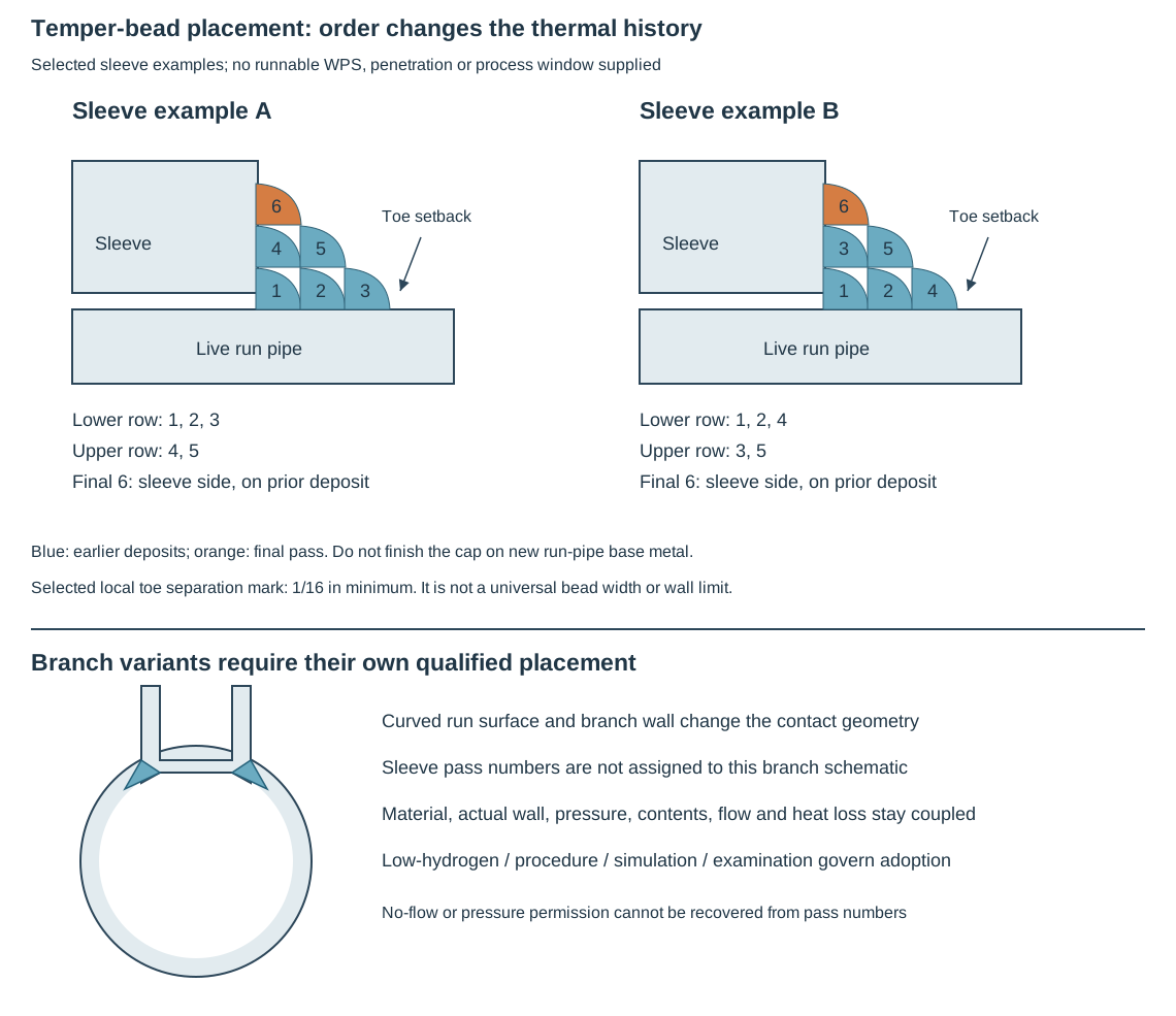
*Figure 21.2. Two selected six-pass sleeve examples preserve different numbered placements. They are not one interchangeable recipe. First-layer contact, subsequent buildup and the final sleeve-side pass are shown schematically. Branch attachments require their own qualified pattern rather than transplantation of a sleeve sequence.* [Structured sequence and conditions](assets/C20/c20-temper-bead-placement.json).
In the first sleeve example, passes 1, 2 and 3 establish the lower row, progressing away from the sleeve. Passes 4 and 5 build above it, and pass 6 finishes at the sleeve side.
In the second, the lower row is 1, 2 and 4. Passes 3 and 5 occupy the next level. Pass 6 again finishes at the sleeve side. The difference is meaningful. The numbers identify deposition order, not simply the final stack height.
The selected illustrations mark **1/16 in minimum separation at the depicted lower-layer/upper-layer toe region**. That local geometric mark belongs to these drawings. It does not supply a universal bead width, electrode travel or penetration limit. The diagram conveys which toe is kept behind the established run-pipe contact boundary, while an executable procedure must define the actual placement and dimensions.
The accompanying branch examples use a different curved run surface and attachment geometry, including different numbers and placements of deposits. The qualified branch sequence must cover its own fusion surfaces, access and thermal response. Reversing a sleeve drawing, changing branch wall or extending a final bead onto previously unwelded run material changes the represented condition. This applies even if the nominal heat-input number stays the same. Record the selected geometry and order with the material, fit-up and live-fluid state. This allows the production welder to reproduce the qualified arrangement and the examiner to locate its critical regions.
The selected historical carbon/low-alloy-steel discussion pairs temper-bead deposition with **low-hydrogen electrodes** and illustrative **3/32 or 1/8 in electrode diameters**. Its attachment chemistry guidance uses IIW carbon equivalent **C + Mn/6 + (Cr + Mo + V)/5 + (Ni + Cu)/15**. The selected maximum is 0.42 below 0.5 in attachment wall and 0.40 at or above 0.5 in. Where only C and Mn are reported it adds 0.03 for the other elements. These are retained method inputs for that attachment discussion, not a chemistry certificate for the live run or a universal qualified range. Actual run chemistry and wall, pressure, contents, heat removal, preheat/interpass state, process and placement remain necessary inputs to the adopted WPS and simulation/qualification.
Its flow discussion divides walls into very thin **0.172 in and less**, thin **0.188–0.250 in**, intermediate **0.25–0.500 in**, and thick **greater than 0.500 in**. The printed categories leave a gap between 0.172 and 0.188 in and share the 0.250 in boundary. Do not invent a category for those conditions.
That historical discussion favors maintained flow for very thin wall. It favors reduced or stopped flow for its thin/intermediate cases to reduce cracking. It describes favorable no-flow/pressure conditions outside the very-thin case. Those statements differ from the [separately adopted flow procedures](#c20-flow-bases), including a procedure that prohibits no-flow welding. They cannot create a hybrid permission to use this bead pattern at unrestricted flow or pressure. Low-hydrogen versus cellulosic penetration, fluid cooling and retained pressure must be evaluated together under the selected route.
The carbon/low-alloy tempering explanation is not a universal material rule. Wet sour service and hydrogen charging keep delayed cracking consequential. Caustic or another service requiring PWHT cannot inherit an online temper-bead substitution, and reactive contents, linings or an unsuitable thermal state can exclude the work.
The selected discussion treats stainless steel differently and does not require temper beads for it. That does not authorize copying a carbon-steel WPS onto stainless. [Production control](#c16-production-control) carries placement, cleaning and examination access into the actual deposit sequence. [Online wall coverage](#c20-online-wall-coverage) locates the run material that must be established before any bead is placed.
### Retain the thermal chart's initial state and welding geometry
A thermal chart lookup must preserve the initial wall state and the welding geometry represented by its axes. The discussed 25°C and 150°C charts are for carbon/carbon-manganese steel with covered-electrode welding. They distinguish first fillet weld, second fillet weld and bead-on-plate/buttering heat-input scales. The horizontal axis shows actual measured wall thickness together with its squared-thickness scale. Selecting a convenient heat-input axis or reading squared thickness as thickness changes the lookup.
Carry the WPS heat-input calculation into its corresponding chart geometry and read maximum inner-wall temperature and penetration as separate outputs. Retain the chart's collapse/risk regions, transition to three-dimensional heat dissipation and the stated limits on extending the lines. A chart for an initial 25°C wall is not evidence for a wall initially at 150°C. Neither establishes another initial condition by an unqualified interpolation. The [structured lookup questions](assets/C20/c20-graph-reading.json) keep the initial state, geometry and quantity references visible.
These charts also show a 4.8-mm reference, and the associated checklist calls for a 4.8-mm minimum. The procedure's body instead states its coupled 5-mm blow-out screen with material, temperature and hoop-stress conditions. Those are not demonstrated equivalent eligibility statements. Retain the existing 5-mm coupled body condition above and the local unresolved 4.8-mm references. Neither rounding downward nor choosing a larger wall alone resolves the full method. Simulation and examination remain the required response under the selected application, rather than a way to disguise an uncertain chart input.
### Follow the recovered thermal contours on the chosen weld scale
The paired native maps add the graphical relationships to the [thermal lookup path](#c20-thermal-chart-path). Their horizontal coordinate is **x = t_a²**, in mm², where **t_a** is the minimum actual measured run-wall thickness in mm. The vertical plotting coordinate **q** is the bead-on-plate/buttering heat-input scale in J/mm. At the same plotted height the first-fillet scale reads **1.5q**, and the second-fillet scale reads **1.25q**. These are scales on the selected graphic, not new efficiencies to apply on top of a WPS heat-input calculation.
For a first-fillet input, use q = HI/1.5. For a second-fillet input, use q = HI/1.25. For bead/buttering, use q = HI. Mixing those scales changes the point being evaluated.
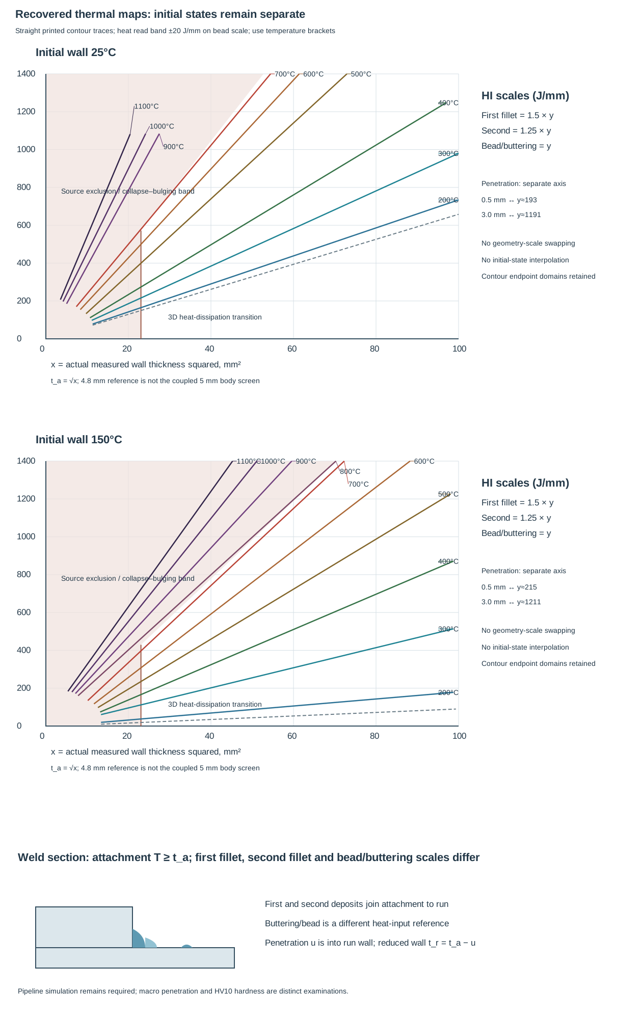
*Figure 21.3. Recovered graphical teaching maps for covered-electrode welding of carbon/carbon-manganese steel. Traced contour segments preserve their visible endpoint domains. Heat readings carry a ±20 J/mm band on the bead scale and the squared-thickness coordinate a ±0.7 mm² reading band. These are recovery bands, not permissible WPS variation. Temperature is read as a contour bracket.* [Structured contours, axes and recovery limits](assets/C20/c20-recovered-thermal-domain.json).
The 25°C map retains its printed 200, 300, 400, 500, 600, 700, 900, 1000 and 1100°C contours. Its absence of a labeled 800°C contour is preserved rather than filled with a new acceptance line. The 150°C map retains 200 through 1100°C at its printed 100°C steps. Each line is a maximum inner-wall-temperature relationship for the selected initial state and chart geometry.
The shaded source exclusion/collapse–bulging region and the three-dimensional heat-dissipation transition are separate features. A point below a contour does not erase a source exclusion region or establish a safe pressure. Where the three-dimensional transition applies, the source describes maximum temperature as independent of wall thickness and/or pipe contents. It does not make every thick-wall, high-heat-input condition independent of its other assessment inputs.
Read penetration **u**, in mm, separately from the right-hand scale corresponding to the selected plotting height. It is not the temperature contour label and is not an additional wall thickness. The pressure evaluation uses **t_r = t_a − u**, retaining the actual-wall and penetration definitions. The structured recovery binds separate right-axis calibrations to the two initial-state maps. It does not infer a common penetration equation or silently shift one initial state into the other. Recovering that graphical read cannot establish actual weld-pool penetration or the hardness of its HAZ.
For a **hypothetical lookup exercise**, take an actual-wall teaching input **t_a = 8 mm** and a first-fillet heat input **HI = 750 J/mm**. This selects **x = 64 mm²** and **q = 500 J/mm**. On the recovered 25°C map that location lies between the 200 and 300°C contours. On the recovered 150°C map it lies between the 300 and 400°C contours. The different brackets demonstrate the initial-state consequence without interpolating a fictitious third initial state.
Reading the separate penetration scales at that height gives a coarse **about 1.1–1.4 mm** teaching envelope. Thus t_r is approximately **6.6–6.9 mm** for the assumed 8-mm wall. The envelope deliberately covers the graphical recovery bands of both separate maps. It does not select a conservative production penetration or approve an operating pressure.
The source permits **horizontal extension of lines for increased wall thickness**. The saved dataset stops at its traced segment endpoints and does not implement that provision as a universal numeric extrapolator. Any use of the source's local extension still has to preserve the selected state, output, exclusion/transition regions and procedure. No interpolation between initial 25°C and 150°C states is established, and initial wall temperature above 150°C calls for specialist advice. Values beyond the printed heat-input range or absent contour endpoints cannot be supplied by extending a fitted line merely because the visible portion is straight.
The chart/checklist **4.8-mm** reference remains unresolved against the procedure's coupled **5-mm** body screen. That screen also depends on yield strength, operating temperature and hoop-stress ratio. A line on the chart does not resolve the material's permitted temperature envelope, reactive contents, hydrogen history or live-fluid cooling. Preserve the [flow and examination basis](#c20-flow-bases) and the [retained-pressure calculation](#c20-welding-pressure) with the actual WPS values, geometry and measured wall.
The source procedure also limits process pressure during the operation to **7000 kPa gauge**, or the equipment maximum if lower. This applies in addition to the calculated welding-pressure limits. The thermal map does not replace these limits.
The required simulation uses an empty pipe with the proposed materials, wall, process, weld configuration, preparation and essential parameters, with inside-surface temperature observations. A marginal or unacceptable preliminary prediction invokes the defined simulation response. **Pipeline applications require simulation regardless of the preliminary result**. For the critical simulated locations:
- Section them to check penetration and macro condition.
- Assess hardness separately by **HV10 under the selected material acceptance basis**.
[Deposit placement](#c20-temper-bead-placement) adds the contact/sequence dimension of that representation. The recovered chart is an inspectable preliminary relationship, not a qualified WPS, hardness result or pressure rating.
### Determine the pressure permitted during welding on its actual basis
A temperature-derating method reduces the wall available at the weld pool and accounts for its temperature-dependent strength. Its equation is:
\[
P=\frac{2S\,t_r\,F\,E\,T_f}{D},\qquad t_r=t_a-u.
\]
In these equations, \(P\) is the calculated permitted inside-to-exterior pressure difference during welding in MPa. For the illustrated atmospheric-exterior applications, the outputs are internal gauge pressures relative to local atmosphere. Other exterior conditions require their applicable pressure-difference and method/route limits. Absolute internal pressure is not substituted for the illustrated gauge quantity.
\(D\) is nominal outside run-pipe diameter in mm. \(t_a\) is the minimum actual wall established by examination in mm. \(u\) is the method’s penetration allowance in mm. \(t_r\) is reduced wall in mm. \(S\) is specified minimum yield stress for the off-plot pipeline calculation, or basic allowable stress for the on-plot piping calculation, in N/mm².
\(E\) is the applicable longitudinal-joint factor, \(T_f\) the temperature derating factor and \(F\) the off-plot design/safety factor. For its off-plot factor the method recommends a maximum of 0.8. For the described on-plot ASME B31.3 basis, that factor is already included in basic allowable stress. It is not applied again as an extra pipeline reduction.
The penetration allowance can come from the selected thermal assessment, or the specifically permitted 3-mm assumption in that method. It is not a measurement of every weld's penetration. The temperature factor uses predicted maximum pipe temperature during welding, rather than normal fluid temperature. Under this adopted table, linear interpolation is permitted between the stated entries:
*Table 21.1. Conditional welding-pressure temperature factors.*
| Predicted maximum pipe temperature during welding | Temperature factor |
| --- | ---: |
| Above 675°C | 0.00 |
| 675°C | 0.20 |
| 600°C | 0.35 |
| 500°C | 0.57 |
| 400°C | 0.65 |
| 300°C | 0.75 |
| 200°C | 0.85 |
| 120°C | 0.91 |
| Below 120°C | 1.00 |
*These are factors for this specified calculation, not a new material-property table for general design. [Structured method data](assets/C20/c20-methods.json) retain their scope and separate quantity definitions.*
For off-plot pipelines, that procedure also calculates a pressure from its applicable toughness/crack-propagation method and takes the lower of the two method results. This is an explicit combined requirement within one adopted basis. Its conversion from the applicable toughness-method hoop stress to pressure is:
\[
P_{tough}=\frac{2S_h\,t_n}{D},
\]
In this equation, \(S_h\) is the corresponding allowable hoop stress in N/mm², and \(t_n\) is nominal thickness in mm. \(D\) remains nominal outside diameter in mm. Pressure follows the stated inside-to-exterior basis in MPa. For the illustrated atmospheric exterior, it is gauge pressure relative to local atmosphere. Fluid, burial and the applicable toughness formulation determine \(S_h\). Nominal thickness here must not silently inherit the reduced-wall definition of the temperature method.
That adopted procedure additionally limits the operation to 7 MPa gauge and to a lower tapping-equipment working rating where applicable, and excludes subatmospheric hot tapping. Those bounds are separate from the two calculated pressures. They remain part of the complete eligibility, process and equipment evaluation.
### Obtain the supported toughness-method stress on its stated unit basis
The toughness method answers whether a crack can propagate unstably in the specified pipeline application. That is a different failure question from local weakening and penetration during welding. The discussed historical method distinguishes fluid type and burial. Its supplied equations for gas and two-phase lines differ between buried and aboveground applications. A higher Charpy value does not erase the thermal method or the tapping-equipment limits.
For the buried gas/two-phase relationship:
\[
S_h=\left[126.9\,MCV\left(\frac{Dt_n}{2}\right)^{-0.333}\right]^{0.5},
\]
For the aboveground gas/two-phase relationship:
\[
S_h=\left[93.19\,MCV\left(\frac{Dt_n}{2}\right)^{-0.284}\right]^{0.5}.
\]
In these equations, $MCV$ is the specified Charpy toughness in **ft·lbf**. $D$ is nominal outside run-pipe diameter in **inches**. $t_n$ is nominal wall thickness in **inches**, and calculated $S_h$ is in **ksi**. The coefficients and exponents belong to these empirical, unit-bound relationships. They do not remain numerically valid after entering millimeters or joules. Nominal wall here remains distinct from the measured, penetration-reduced wall of the thermal method.
The method calls for minimum average values specified for procurement and confirmed by certificates where possible. These are at minimum pipeline design temperature or lower, using full-size 10×10-mm transverse specimens. It also states a minimum of 10 ft·lbf, approximately 14 J, for its high-vapor-pressure-liquid, buried-gas/two-phase and aboveground-gas/two-phase applications. That rounded equivalence is not permission to enter a joule value directly as $MCV$.
The separate high-vapor-pressure-liquid formulation is not supplied in this account and depends on its referenced assumptions/graphs. It cannot be recreated from the two gas equations. Its no-additional-requirement statement for specified land water/stabilized-liquid pipelines concerns this particular toughness check, not every pipeline design or hot-tap requirement.
The [structured toughness companion](assets/C20/c20-charpy-hoop-method.json) retains the equations, method units, rounded 1 ksi = 6.895 N/mm² conversion and hypothetical calculations. Apply the lower thermal/toughness result and separate 7-MPa-gauge/equipment caps; a toughness conversion alone is not an operating permission.
Compare the required methods only within the one adopted off-plot basis, with a consistent pressure reference. These historical equations and teaching inputs do not establish a current fracture-control qualification or accept a pipeline.
## Preserve the distinct flow and examination conditions
One adopted online-welding practice prohibits no-flow welding and uses a minimum velocity of 1.3 ft/s. It suggests a maximum liquid velocity of 4.0 ft/s and procedure adaptation for excessive cooling.
Another adopted method permits its assessed no/intermittent-flow case only when the required absence of an explosive/flammable mixture and oxygen ingress is confirmed. Otherwise, it uses its defined purge arrangement. Its suggested maximum liquid velocity is 1.75 m/s, with heat-loss testing and procedure response above that value. Both preserve acceptable interpass temperature. Neither provides an unrestricted gas-flow permission independent of that condition.
A separate historical checklist’s flow-reduction instruction excepts wall at or below 0.188 in. That local statement remains distinct from both adopted flow procedures. The values are not one envelope assembled from the lowest minimum and highest maximum. Choose the applicable procedure and its whole material/fluid/thermal/operating basis. For unstable flare duty, the specified purge, instrumentation and fast warning functions are part of the selected application. A nominal average velocity measured before the job cannot establish continuous conditions through welding and cutting.
Examination also has purpose and timing. Establish actual wall, laminations/defects, ovality and the soundness of relevant nearby welds before attachment. Inspect the qualified attachment as specified during and after welding, including the applicable hardness and delayed-cracking examination. One practice uses a 48-hour delayed examination with defined metallurgical adjustment provisions. Another references its selected weld-inspection procedure. An immediately clean surface examination is not proof that a later hydrogen-assisted crack cannot develop.
The personnel, method and acceptance basis must be appropriate to the material and feature being examined. Magnetic-particle, penetrant, ultrasonic, radiographic and hardness evidence address different questions. [Examination](#chapter-c16) develops them. Keep the actual online thermal/process state and any delayed verification with the evidence.
The [structured procedure distinctions](assets/C20/c20-procedure-distinctions.json) retain the separately adopted thickness, flow, examination and testing scopes for this comparison.
### Survey the proposed attachment footprint, not a nominal pipe wall
A hot-tap wall survey is located by the actual tie-in center and proposed weld line. Measuring an accessible point elsewhere on the run does not establish the material beneath a planned attachment. The selected footprint drawing therefore combines a general surface grid with a separate series of measurements around the attachment weld line. Keep the coordinates of the proposed center and weld footprint recoverable after cleaning, surveying and fitting placement. Moving the attachment after examination can move the weld onto material that was never examined.
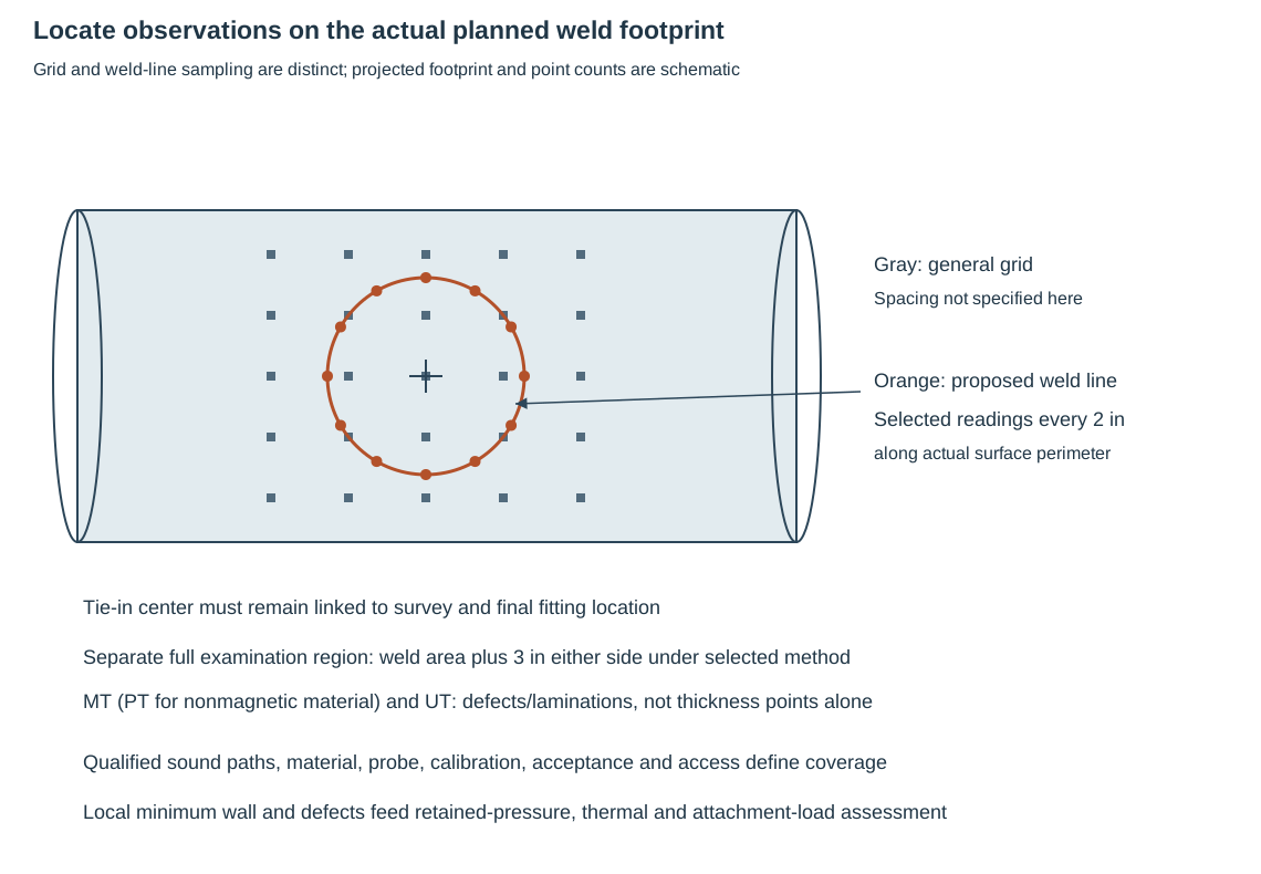
*Figure 21.4. Selected measurement-location example: readings every **2 in along the weld line**. The general grid spacing is undimensioned. Drawn point count and projected circular appearance do not establish actual circumference, complete scan coverage or acceptance.* [Structured footprint and coverage distinctions](assets/C20/c20-online-wall-coverage.json).
The grid supports a spatial picture of actual thickness and local variation. The weld-line observations address the perimeter where the attachment will transfer heat and load. The 2 in instruction applies along that actual weld line on the pipe surface, not to every horizontal or vertical grid interval in the sketch. A projected circle on a curved run is not a dimensioned flat template. Establish the actual attachment perimeter and survey coordinates under the adopted method rather than scaling this illustration to obtain a count or a physical diameter.
A companion preweld requirement fully examines the **weld area plus 3 in on either side**. It uses magnetic-particle examination, or penetrant for nonmagnetic material, and UT to locate defects and laminations. That region is a separate examination obligation. The 3 in width is not the weld-line sampling pitch. Thickness readings alone cannot demonstrate the required lamination search or sound path through the intended volume.
A local checklist’s 3-in seam-distance question remains subject to its body’s exception/review route; it cannot override another method’s weld-separation rules. Probe, coupling, material, surface, curvature, calibration, coverage and acceptance criteria must suit the feature being assessed. [Examination evidence](#c16-examination-evidence) distinguishes these questions from a generic “UT complete” entry.
Record the evaluated minimum wall and local anomalies in the proposed weld/load region, together with pipe ovality, existing weld locations and relevant flaws or laminations. Use those actual conditions in the retained-pressure/thermal assessment and in the [attachment and machine load evaluation](#c20-connection-loads). The welding condition reduces effective strength and can consume part of the load-carrying thickness. One original nominal schedule or an average of grid readings is not the wall remaining beneath the critical bead. A relocation, different fitting footprint or changed support position reopens the affected coverage and design inputs.
The selected route also requires pre-machine visual inspection, root/cap surface examination, weld/HAZ hardness and normally 48-hour delayed examination with its defined metallurgical adjustment. The surveyed footprint does not replace those stage/access requirements. [Temper-bead placement](#c20-temper-bead-placement) connects the surveyed material to the actual thermally affected region.
## Make the attachment, valve and machine one evaluated configuration
A branch removes part of the run wall when drilled. Reinforcement and remaining pressure strength must cover that changed geometry. A conventional area-replacement method can be appropriate within its application. A highly stressed pipeline with a large branch ratio may require a more rigorous local assessment. Pressure adequacy also does not establish that the run pipe carries the valve and tapping-machine loads acceptably.
Cantilever weight can bend the run pipe or buckle the local wall at the branch. An off-vertical machine can also twist it. Provide the evaluated support and clear working space in the actual drilling position. One design procedure applies a factor of 2 to its calculated tapping-load stress contribution before combination with pressure stress. This is a specified assessment allowance, not a prediction that the machine physically doubles in weight or a universal dynamic factor for every pipe load.
For a connection procedure specifically adopting the following reduced-fitting limits, retain both size and ratio conditions:
*Table 21.2. Conditional reduced-fitting size and diameter-ratio limits.*
| Application | Maximum branch size | Maximum branch/run diameter ratio under this method |
| --- | --- | ---: |
| On-plot piping | DN 75 | 1/3 |
| Off-plot pipeline | DN 50 | 1/4 |
*Its reduced-fitting minimum is DN 25 and these fittings are excluded where vibration is expected. Retain the method's diameter convention. The ratios do not define an internal-area calculation.*
Reinforced set-on branches and full-encirclement sleeves form other choices. A preformed split tee can serve a stopple or a connection arranged for subsequent pig passage. Its annular gap can introduce a fluid-dependent corrosion issue. These alternatives have different joining, test and local stress conditions. A full-bore valve must allow the actual cutter to pass and close after retraction. Nominal branch size alone does not prove that clearance.
Location affects both loading and debris. A downward-oriented tapping configuration on a horizontal line can simplify support and reduce the tendency to retain swarf near the isolating valve. Existing welds, deposits, local corrosion and pipe ovality also constrain the site. The selected weld-separation/attachment rules must be retained with the adopted procedure rather than borrow one clearance dimension from another basis. Upstream sensitive equipment needs the specified swarf protection or another evaluated means.
A cut coupon can spring or jam, especially in some large or spiral-welded pipes. A selected reinforcement/retention arrangement must preserve the cutter/retraction and valve-closing functions. The branch opening can be smaller than its nominal internal bore, and a retained plug or later pig operation imposes other geometry. [Branches](#chapter-c07) and [pipeline/pigging interfaces](#chapter-c11) carry those relationships beyond the original cutting task.
### Separate the maintained service path from the section being removed
A temporary bypass and two plugging sites can create an alternative topology for local pipe replacement without losing the intended service path. The bypass joins the live upstream side to the live downstream side outside the section bounded by the plugging locations. The old section between them is the work section. It is not the bypass. Lying between two drawn plugs does not establish that it is an isolated pressure volume.
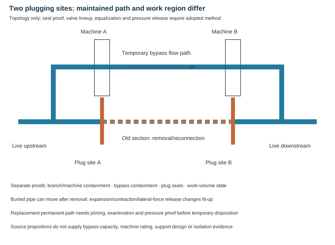
*Figure 21.5. Authored topology based on the selected two-machine arrangement. Solid blue is the intended maintained path. Orange boundaries identify plugging sites. The dashed old section is the removal/reconnection work region. No valve lineup, seal proof, pressure equalization sequence, bypass size or machine capacity is inferred from the drawing.* [Structured boundary questions and restoration states](assets/C20/c20-temporary-bypass-boundaries.json).
The topology creates several simultaneous pressure-boundary questions:
- Containment at each installed branch/plugging machine
- The temporary bypass itself
- Each plug-to-run interface
- The work section’s actual isolated/depressurized state
Their proofs are different. A passing attachment pressure test does not establish plugging seal performance. Observed bypass flow does not establish zero pressure or no ingress in the removed section. The adopted supplier/project method defines seal verification, leakage response, monitoring, pressure equalization and safe release. The figure supplies locations for those questions rather than answering them with generic actions.
Service continuity also needs an evaluated bypass path. Its inputs include actual fluid, pressure/temperature, required flow, allowable pressure loss, temporary component ratings, supports and load cases. The plugging-machine and bypass connections must remain compatible with the live run during installation, use and removal. A nominally available route can still fail its capacity, thermal, access or support requirement. [Connection and machine loads](#c20-connection-loads) apply to the actual bypass and plugging configuration. No bypass sizing follows from line proportions in this sketch.
Removing a buried section can release expansion, contraction or lateral forces and move the cut ends. The replacement needs actual released terminal positions, support/restraint assumptions and joining allowances. Unplanned pull-up through the new spool or bolting can retain stress; [pipeline modification](#chapter-c11) and [fabrication datums](#c17-spool-description) govern the changed fit.
The restored path has new joints, pressure boundaries and possible permanent plugs/branches. Its joining, pressure proof, coating/cathodic protection and support state must suit that permanent configuration before removing temporary bypass/machine supports under the selected method.
### Separate the wetted branch from its reinforcement and enclosure
The three selected branch alternatives change which surfaces contain fluid and which welds supply reinforcement. A reduced branch fitting creates its outlet locally on the run. A reinforced set-on branch has its own run-to-branch pressure connection, with a surrounding sleeve providing reinforcement. In the selected set-on illustration **fluid does not contact the reinforcing sleeve**, and the branch flange is omitted from that view.
A preformed split tee instead supplies its own outlet and encircling shell with longitudinal joining. After perforation, its annular space can communicate with the process. A dry reinforcement assumption cannot be transferred from the set-on sleeve to every encircling attachment.

*Figure 21.6. Reduced fitting, reinforced set-on with dry sleeve, and preformed split tee with annular interface. This is a qualitative contact/load comparison, not reinforcement sizing. Flange omission in the set-on view does not eliminate its valve/machine interface.* [Structured functions and conditions](assets/C20/c20-branch-interface-geometry.json).
The [reduced-fitting size/ratio limits](#c20-connection-loads) jointly define that selected category. A larger reinforced set-on branch has its own assessment; this route prefers a full-encirclement sleeve over a pad/saddle and requires at least one nominal size below the run, except its selected stopple case. The cut opening remains smaller than branch ID.
A split tee designed for full pipeline pressure can provide plug/pigging or full-bore stopple interfaces in this selected connection method. Its small annular gap introduces a corrosion question for some fluids. A different adopted method excludes its split-tee route in corrosive/steam service where crevice corrosion is accelerated. It normally treats the fitting as temporary, with replacement and regulatory routing. It separately permits consideration of permanence for non-expansible-fluid systems under its consultation requirements.
These eligibility and permanence bases remain distinct. The three-interface drawing cannot override either. Keep component material, sour-service suitability, longitudinal/end-weld function and required examination/test sequence with the selected route.
The [machine-load assessment](#c20-connection-loads) remains separate from pressure strength and must match actual orientation, branch height, working space and subsequent piping loads.
### Fit the cutting and retraction states through the same valve
The drilling machine, isolating valve and branch form a stack whose geometry must work in all three states below. The machine drives a boring bar, pilot and cutter through the open valve and branch toward the live run wall. The opening establishes a new live fluid path. The cutter and retained coupon must then retract far enough to clear the valve's moving closure member. Only after verified retraction can the valve close and isolate the machine-side volume for controlled pressure release and removal.
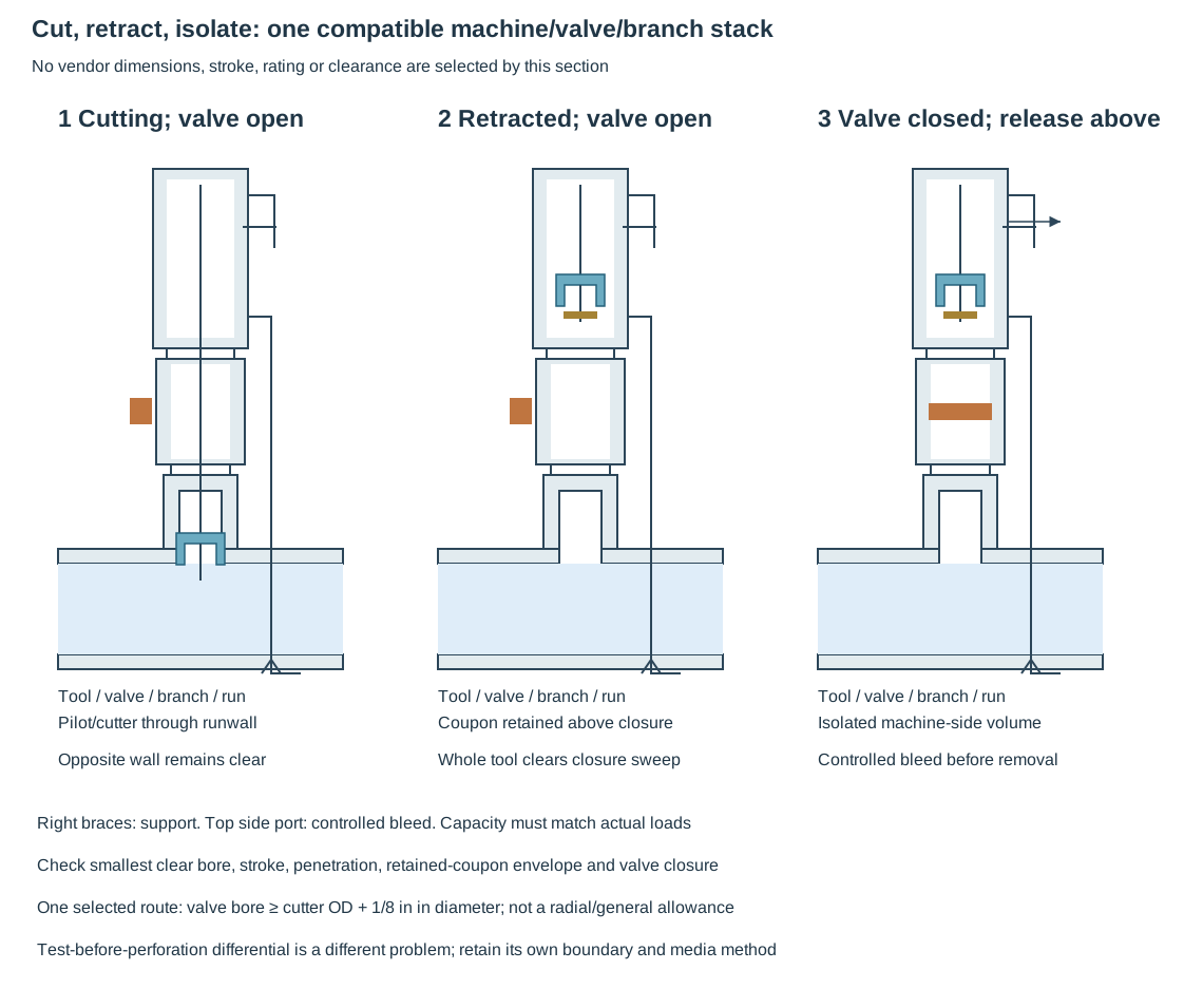
*Figure 21.7. Conceptual three-state section. Cutter travel, coupon envelope, branch length, opposite-wall clearance, valve closure and machine support require equipment-specific dimensions and loads. The schematic supplies no stroke, rating or clearance measurement.* [Structured state and interface checks](assets/C20/c20-cutter-valve-envelope.json).
Check the actual smallest clear bore through valve, flange/adaptor and branch against the cutter and retained-coupon envelope. In one selected inspection route, the valve has a clear full round opening at least **1/8 in greater in diameter than the specified cutter/drill OD**. That is a diametral condition for its route, not a radial allowance or a general clearance for every cutter. Bore alone does not establish adequate stroke. The stack height and branch length must permit the intended penetration and full withdrawal. A short branch reduces leverage, yet it must still accommodate the selected cutter/pilot travel and a place for the coupon above the valve closure envelope.
Establish the cutting depth against the actual run geometry so that the pilot and cutter do not strike the opposite wall. The coupon can spring or jam, particularly in some large or spiral-welded pipe. Where selected, its reinforcement device is installed before the connection hides the run surface. Retention, cutter compatibility and the retrieval envelope remain part of the machine method. A successful pilot penetration is not completed coupon retrieval, and a retrieved coupon is not evidence that the finished valve can isolate. Swarf protection and downstream equipment/pigging consequences belong with the evaluated cutting and contingency plan.
The machine pressure boundary includes its seals, packing and adaptation to the valve. Ratings and compatibility must match the actual pressure, temperature and contents. A historical illustrative machine arrangement provides no manufacturer stroke or rating.
The external bleed/drain connection addresses the isolated machine-side volume after the valve is closed. Verify the actual isolated state and controlled release under the manufacturer's method before removing flange bolts. A vent reading alone does not establish that every trapped pocket has drained, especially where hot liquid remains above a closure member. The [test boundary and media sequence](#c20-test-sequence-media) remains a separate preperforation problem. Pressure testing against an intact run wall is not a demonstration of cutter travel or valve-closing clearance.
## Test the added boundary without collapsing the live run pipe
Before perforation, the branch/fitting test can pressurize the outside of the still-intact run wall. The external differential can govern buckling even when the new branch itself is strong enough. A higher test pressure is therefore not automatically a more useful verification.
A split-tee test procedure using the stated external-pressure basis uses:
\[
P_T=P_A+\Delta P_{allow}.
\]
In this equation, \(P_T\) is the fitting/branch test pressure. \(P_A\) is actual operating pressure inside the run pipe during the test. \(\Delta P_{allow}\) is the established allowable external differential for that run-pipe configuration. Use consistent pressure units and reference. The allowable differential needs the applicable external-pressure calculation, such as the specified ASME VIII Division 1 UG-28 route under the adopted method. It is not supplied by the branch pressure class.
If the actual run pressure changes while test pressure remains held, the differential changes too. With hypothetical \(P_A=2.0\) MPa and an independently assumed allowable differential of 0.4 MPa, the relation gives \(P_T=2.4\) MPa. If \(P_A\) falls to 1.7 MPa without changing the test, the external differential becomes 0.7 MPa, exceeding that assumed allowance. This demonstrates why operating-pressure control/observation and the contingency belong to the test basis. It establishes no actual pipe's buckling capacity. The applicable branch/code test ceiling also remains a separate limit.

*Figure 21.8. Authored pressure-condition schematic, not a split-tee design detail. Test pressure acts outside the intact run wall while process pressure acts inside. Their difference must stay within the evaluated run-pipe allowance. [Structured method data](assets/C20/c20-methods.json) preserve the illustrative values and distinct bounds.*
A set-on branch uses a different local buckling/test method. Its graph-based assessment uses actual operating stress relative to specified minimum yield, outside run/branch diameters and actual run wall. The stated graph simplification assumes equal branch and run thickness. It is described as conservative for buckling in the normal case where the branch wall is thinner.
Where that assumption or conservative condition does not hold, use the specified alternate formula rather than the graph. Its test pressure may not exceed the branch design-code test pressure. Do not use a split-tee differential allowance as a universal set-on value or apply the graph's pipeline stress-ratio convention without its defined scope.
### Read the set-on test ratio from its actual geometry and stress family
For the discussed set-on chart method, choose the family $F=S_{h,op}/SMYS$ from actual operating hoop stress and the material's specified minimum yield stress. This $F$ is an operating stress ratio. It is not automatically the pipeline's selected design factor. Use actual run diameter/wall ratio $D/t_a$ to select the curve, and branch/run outside-diameter ratio $d/D$ for the horizontal coordinate. The vertical read is $P_T/P_A$. Each ratio is dimensionless, but its diameter, thickness and pressure quantities must still share the stated measurement/reference basis.
As a hypothetical coordinate example, let $D=400$ mm, $t_a=8$ mm, $d=200$ mm and $SMYS=245$ N/mm². Assume operating pressure $P_A=5.88$ MPa on the atmospheric-exterior gauge basis. A simple hoop input $P_AD/(2t_a)$ is 147 N/mm², so $F=0.60$, $D/t_a=50$ and $d/D=0.50$.
The displayed curve read is about 0.55. This teaching comparison retains a coarse 0.50–0.60 read band rather than imply more precision than the plotted observation. Multiplying by the assumed $P_A$ gives approximately 3.23 MPa, with a 2.94–3.53-MPa teaching band. These are graph-reading arithmetic, not a test-pressure approval or a derived buckling capacity.
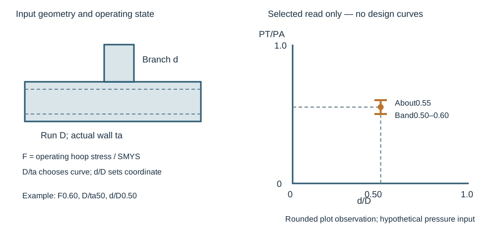
*Figure 21.9. Authored lookup schematic and selected rounded plot observation. The marked band illustrates the stated $F=0.60$, $D/t_a=50$, $d/D=0.50$ read. It is not a reconstruction of complete design curves or a new accuracy criterion. [Structured lookup geometry and data](assets/C20/c20-graph-reading.json) retain the hypothetical inputs, read band and eligibility limits.*
The chart's equal branch/run-wall assumption and stated conservatism for a thinner branch remain necessary. A thicker branch or an unrepresented configuration requires the applicable alternate method, whose underlying formulas are not supplied here. The source also gives specific conservative uses at lower on-plot stress ratios and smaller diameter ratios. Those bounded provisions do not create a general extrapolation rule. Finally compare the result with the branch design-code test ceiling, the evaluated welding/process condition and equipment limits. The split-tee relation $P_A+\Delta P_{allow}$ answers a different configured test problem and cannot replace this lookup.
### Compare configured set-on test-ratio curves
The two-panel recreation adds the missing plotted domain beyond the [single set-on teaching observation](#c20-seton-chart-reading). The upper panel contains **F = 0.60 and 1.00**. The lower contains **F = 0.50 and 0.72**. Each family contains **D/t_a = 30, 50, 80 and 120**, with its own line style.
Here F is actual operating hoop stress divided by SMYS. D is run outside diameter, t_a is actual run wall, and d is branch outside diameter. The horizontal ratio **d/D** and vertical ratio **P_T/P_A** use those actual references. F must not be silently replaced by the safety/design factor used in a different welding-pressure equation.
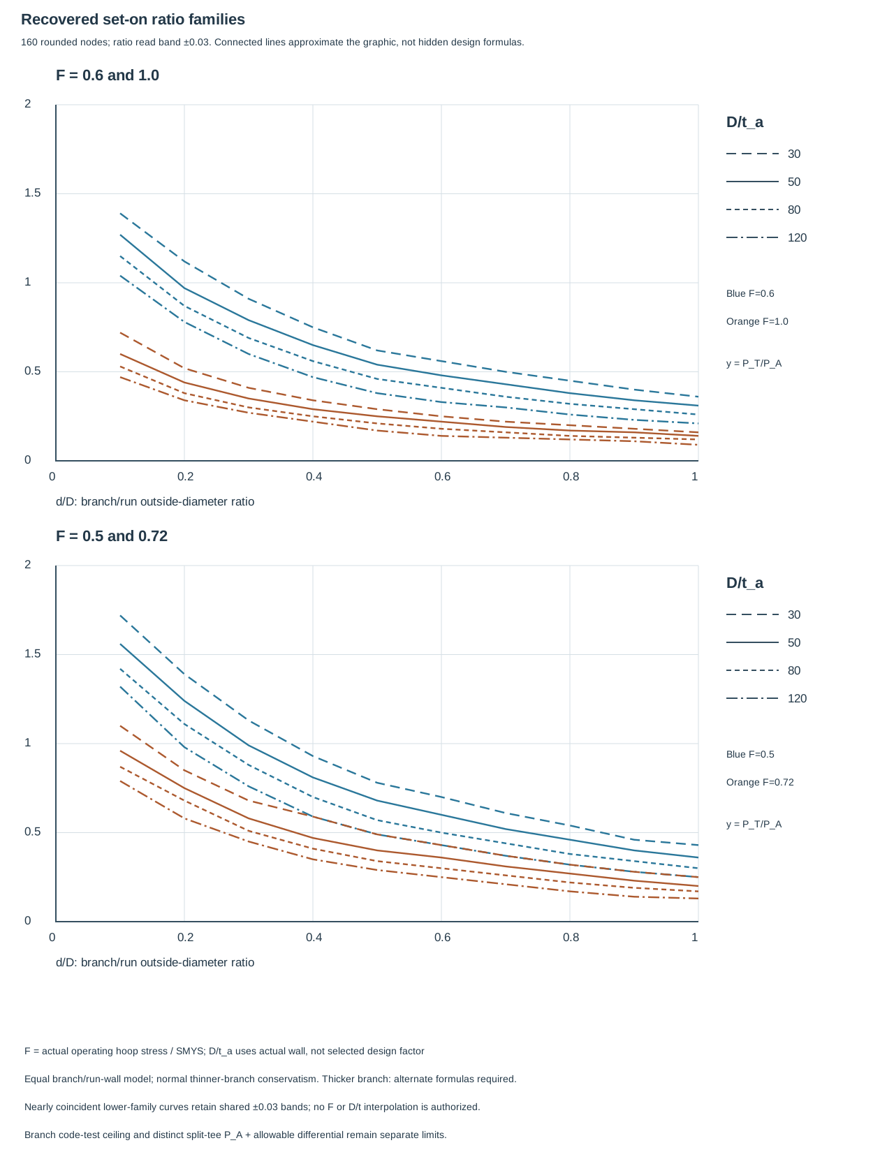
*Figure 21.10. Graphical teaching recovery of sixteen configured curves over d/D = 0.10–1.00. Rounded node readings carry a ±0.03 ratio band and ±0.012 horizontal-coordinate band. These bands describe recovery from the graphic, not engineering scatter or a pressure-test acceptance margin. Connecting nodes supplies a graphical approximation. It does not introduce an approved interpolation rule between stress or wall families.* [Structured curve nodes and limits](assets/C20/c20-recovered-seton-domain.json).
Choose a represented F and D/t_a pair before moving along d/D. Increasing the branch/run diameter ratio reduces the plotted test-pressure ratio in each recovered series. Changing the wall ratio or operating-stress family changes the result at the same branch ratio. A visually nearby curve is not a substitute for a missing configuration.
The source’s actual legends govern the recovery. Conflicting historical captions that name an F = 0.8 family or D/t = 60 are not data for these panels. The saved curves retain their actual displayed families and do not construct those absent curves.
For a **hypothetical comparative read**, take d/D = 0.50 and D/t_a = 50. The recovered ratios are approximately:
- **0.68 at F = 0.50**
- **0.54 at F = 0.60**
- **0.40 at F = 0.72**
- **0.25 at F = 1.00**
Each has its ±0.03 graphical band. These are separate configured observations rather than one pipe whose pressure or material is assumed to satisfy all four cases. They expose how selecting the wrong family can materially change the proposed branch test pressure.
For the particular hypothetical F = 0.60 case already developed above, P_A = 5.88 MPa. The recovered 0.54 band **0.51–0.57** would give P_T approximately **3.18 MPa**, with a **3.00–3.35 MPa graphical band**. This narrower recovery band is not a replacement for the earlier deliberately coarse 0.50–0.60 teaching band. Both express an approximate observation rather than an accuracy certification. The product P_T = (P_T/P_A) × P_A keeps actual run pressure visible, but the arithmetic alone does not establish an allowable test pressure.
Near larger d/D, some lower-panel lines nearly coincide. In particular, the F = 0.50, D/t_a = 120 curve and F = 0.72, D/t_a = 30 curve occupy shared graphical read bands. Their saved rounded centers can agree while their configuration identities remain separate. That agreement is not evidence that the underlying models or configurations are identical. The recovery does not invent separated numerical values below the resolution of the plotted lines, and it does not infer their generating formulas.
The model assumes equal branch and run walls and is stated to be conservative against buckling for the normal thinner-branch case. A thicker branch requires the selected alternate formulas from the underlying report. Those formulas are not supplied by this recreation. The particular on-plot use of F = 0.50 for a lower actual stress ratio, and conservative use for d/D below 0.10, remain source-specific provisions. The saved domain begins at 0.10 and does not convert either into a general extrapolation rule. Compare any selected result with the **branch design-code test ceiling**, actual test-state run pressure, attachment and equipment limits, temperature/media conditions and the adopted approval route.
This is the **set-on branch-before-perforation** test problem, where a still-intact run-wall patch lies beneath the branch test pressure. The [dry reinforcing sleeve interface](#c20-branch-interface-geometry) must not be confused with a split tee enclosing an annulus. The split-tee method uses **P_T = P_A + ΔP_allow**, where ΔP_allow comes from its separately evaluated run-wall external-pressure/buckling assessment. Its fluid contact, test medium and external differential are different configured questions. Preserve the existing [test-boundary explanation](#c20-test-boundaries) and [test sequence/media](#c20-test-sequence-media). No set-on ratio curve supplies a split-tee buckling calculation, a machine leak-test requirement or a permissible welding flow state.
### Verify each seal and test state under its own conditions
One adopted sequence distinguishes three tests before cutting:
- Leak testing the hot-tap valve, preferably separately so the correct seal is evaluated
- Testing the completed branch with the valve installed/open for strength and leak tightness
- Leak testing the mounted drilling machine with the valve closed
Its stated minimum durations are five, thirty and five minutes, respectively. Valve/machine leak tests use the highest run pressure that could occur during the operation. Branch test pressure follows its separate calculated basis. Passing one test does not establish all three seals or states.
Select media from the governing procedure, surface temperature, contamination and stored-energy conditions. One method prefers water where practical and considers a compatible alternative to avoid water in a split-tee annulus. It excludes gas testing above 7 bar gauge unless its risks and mitigation are fully assessed. Another limits its hydrostatic branch test to skin temperature of 93°C. It specifies nitrogen or helium above that condition, with its own staged pressure/stabilization and protection requirements. These are separately adopted methods, not a combined universal temperature/pressure permission.
Before perforation, the intact live wall gives the branch test a different load, temperature and external differential from the open service connection. Limits on run-pressure change remain part of the test. See [testing and restoration](#chapter-c18).
## Carry the evaluated conditions through cutting and special applications
Cutter/coupon retention, machine stroke and valve-closing clearance must remain compatible under the actual process conditions. Leakage, a stuck coupon or lost process control requires the selected contingency/isolation arrangement. Downstream debris protection must be available during cutting.
After the opening is made, the branch becomes part of the live system. The valve and remaining connection must carry the service and loads assigned to them when the machine is removed. Reinstatement and examination must establish that actual end configuration, including any plug, temporary valve removal or later branch piping. Under the specifically adopted completion procedure, the branch is blanked off immediately after removal of the drilling machine. The required coating, site and cathodic-protection condition is restored.
Retain the cut coupon as applicable for evidence of local internal pipe condition. This removed wall piece is different from a corrosion-monitoring coupon. A lost cut coupon is a changed condition requiring evaluation of downstream damage and pigging, not a completed retrieval. A successful coupon retrieval does not establish all the resulting connection functions.
Tank hot work is a distinct application. Liquid level, vapor-space ignition, plate strength/thickness/carbon content, impact/heat-treatment history and the selected nozzle geometry matter. One specifically adopted tank procedure requires at least 1 m liquid head above the hot-work region. Another specifies 3 ft. Within the particular 1-m-head procedure, ordinary tank welding is limited to mild-steel shell plates with these conditions:
- Yield strength not above 240 N/mm²
- Maximum 12.5-mm thickness
- Carbon content below 0.23%
Other steel needs its specifically accepted basis.
Its heat-treated major-nozzle plates are excluded, and the required simulation hardness/impact work must use identical material with the same thermo-mechanical history. The differing head figures do not erase these material, operating and test conditions. Pumping, heating-coil operation and roof/above-liquid hot work restrictions remain with the selected procedure. A pipe-wall qualification cannot be transferred automatically to a heat-treated tank plate or pressure-vessel nozzle.
Pressure vessels and miscellaneous cast/fabricated equipment also have different geometry and manufacturing concerns. The illustrated pipe hot-tap methods discourage or exclude such applications within their own scope. Flare lines combine uncertain/intermittent flow with changing mixture and disposal duties. The selected purge and fast warning arrangement must be established, not inferred from ordinary gas-line velocity. [Equipment](#chapter-c06) and [service hazards](#chapter-c13) supply the additional physical context.
## Retain the repair's technical intent through return and removal
Return to service must establish the intended containment, isolation, loading, cleanliness and protective functions of the resulting configuration. Remove or retain temporary items according to that evaluated state, not a generic rule that all temporary steel disappears. A strongback needed for joint retention, an inspection access or a temporary sealant-heating arrangement can remain consequential through the repair life. Its continued presence and operating constraints must be visible to later operators and maintainers.
A temporary repair retains its evaluated deterioration/life, enclosure/wrap function, exposure/temperature limits, monitoring access and end disposition. Reinjection, retorque, changed duty or unexpected damage can invalidate that basis.
A permanent changed design also needs the affected neighboring assumptions re-evaluated. Added branch mass, new isolation inventory, revised flow, a changed restraint or another material/lining can alter equipment reactions, protection, cleaning and inspection. [Continuing integrity](#chapter-c19) and [technical continuity](#chapter-c21) connect these effects through the operating life. The useful endpoint is the demonstrated system configuration and its maintained service basis, with an inspectable route to the next intervention.
# Chapter 22 — Engineering records, human factors and lifecycle decisions
## A useful record explains the installed decision
An evaluated piping arrangement depends on actual component identity, service state, settings, geometry and support/contact conditions. A sliding guide differs from a loose attachment; a calibration reference differs from an uncorrected offset; a temporary filled test state differs from the service arrangement. The record must locate those physical distinctions, not only the line tag and pressure class.
A process diagram supplies function and connections; layout supplies position and working space; calculation supplies its model, loads and criteria; fabrication/inspection and as-built information supply what was made, examined and installed. A statement in one representation does not establish all these conditions.
## Use information at the maturity it can support
A preliminary vendor envelope can support alternative equipment arrangements. It does not necessarily support final nozzle connections or a fabrication spool. Internally generated equipment information can be sufficient for a study while the selected supplier data is pending. When the confirmed outline arrives, compare the consequential differences rather than simply file it alongside the earlier assumption. A change in nozzle projection, weight, actuator height or withdrawal length can reopen several neighboring decisions.
An assumed removal envelope supports arrangement comparison but does not establish final withdrawal clearance. Preliminary line size can support routing while hydraulics and quantities remain unresolved. Final spool/connection dimensions require confirmed equipment data.
A certified drawing establishes a particular supplier representation and revision. Its status should not be extended into a claim that every connected pipe, support or operating task has been evaluated. Likewise, a calculation marked complete should retain its input identity and state. A later geometry or service change can invalidate its applicability without changing the calculation file itself.
## Keep line identity and physical attributes consistent
Line identification allows process, piping, fabrication and operating participants to refer to the same intended service and route. A convention may combine unit, service, sequence, nominal size, material class, insulation and other information. Those fields have different meanings, and identification conventions vary. Adopt the actual project convention without turning one organization's syntax into a universal engineering rule.
The identifier is not a substitute for the physical data. A line can change size, class or other attribute along its route under a specified convention. A class break can require another identifier or a defined segment and exception. The adopted basis determines that treatment. Do not infer that every component sharing a line number necessarily has the same dimensions or allowable conditions.
Preserve where an attribute applies. A size or material entry must connect to the relevant segment or component. A nominal pipe size and schedule identify a selection category. They are not measured inside diameter or wall thickness.
A pressure class is not an operating pressure. Design, operating, upset and test conditions should retain their state and pressure reference, and a minimum temperature at pressure should remain paired with that pressure. [Materials](#chapter-c02), [pressure design](#chapter-c08) and [testing](#chapter-c18) develop the technical use of these distinctions.
Units and meaning need to travel together. A pressure stated in psig, an absolute pressure and a pressure difference are not interchangeable records even when their numerical strings look similar. Force and moment require their respective units and directions. Fluid temperature, metal temperature and a thermal displacement can describe different inputs to one evaluation. A field named temperature without its state, location and purpose can conceal the condition that actually governs the decision.
Unknown, not applicable and zero also have different meanings. A missing equipment load limit is not a zero allowable. A zero imposed movement is an input, not proof that movement was never considered. Identify unresolved data and its effect on use rather than populate a blank with a convenient value. Keep significant precision and a declared conversion or rounding basis where it affects a result.
The selected service/class, component revision, valve mass, support state and calibration fluid/range must apply to the same physical segment across P&ID, line list, isometric, mechanical model and instrument record. Matching a tag alone does not establish that agreement.
### Translate the convention without translating away the engineering
An identifier needs its namespace and dictionary. The same service letters can identify high-pressure steam in one convention and hydrogen sulfide in another. A letter used for clean condensate elsewhere can identify caustic. A shared character string is therefore not evidence of a shared fluid. When combining records from different units or projects, first establish which convention assigned the identifier and what each field means. Preserve the original reference alongside the resolved item rather than match records by an unqualified service code.
A composite convention can explicitly carry unit, service, sequence, size, schedule, material specification, insulation thickness and insulation purpose. Another can order these differently or omit a unit prefix inside a defined battery limit. A shorter purchasing identifier may point to a fuller specification. It does not itself contain that specification. Resolve the selected item and revision before using the code for procurement, replacement or analysis. A supplier can retain a catalog label while changing the supplied design, so the label must be checked against the actual required construction and service.
Trace identity through the physical route as well as across documents. A selected numbering scheme can retain one number across a reducer or a control-valve bypass. It can assign new numbers to branches or equipment connections and leave particular instrument connections unnumbered. Another adopted scheme may draw those boundaries differently.
Record the topology and the applicable size or class segments independently of the convention's number changes. A line number remaining constant across a reducer does not turn two bores into one hydraulic input. An unnumbered instrument connection remains a physical pressure path requiring its own design and restoration.
A resolved identity binds the original convention to a physical item/segment and its applicable fluid, material and allowable conditions. An unresolved service code or class exception cannot be treated as a confirmed engineering input. See [components](#chapter-c03), [flow geometry](#chapter-c07) and [sensing paths](#chapter-c22).
## Give each representation the information needed for its job
Spool/isometric information must define actual geometry, component/material identity, joint locations and dimensions for the selected shop, module or field-fit construction. [Fabrication](#chapter-c17) supplies those dimensional interfaces. A model clash check cannot detect an omitted work envelope or field-run connection, and quantities from an incomplete selection remain incomplete.
Instrument records connect the process function to device, range, connection, signal and receiving arrangement. Installation details and loop information can include the selected calibration, supplier model and input/output role. A later replacement or service change should be connected to those records, not treated as a new tag with the old loop assumed valid. [Measurement and control](#chapter-c22) supplies the sensing and mode basis.
Calculation and evaluation records need their own state and interfaces. Geometry, material, contents, temperatures, contact/restraint conditions, equipment movements and selected allowables should remain identifiable. Outputs should distinguish the result and its applicability from the criteria used to judge it. A stress result, a nozzle-load comparison and a supporting-structure check address related but different acceptance questions. [Analysis](#chapter-c09) and [supports](#chapter-c10) develop their physical evaluations.
A safety-critical item's credited protective function requires the actual scenario, performance basis and configuration; an equipment tag or filled SIL field does not establish capacity, independence or a test interval. Local criticality classifications are not universal exemptions from piping integrity. See [protective systems](#chapter-c08) and [functional integrity](#c19-functional-integrity).
## Reuse an evaluated family, not an unexamined drawing
A reused arrangement applies only to installations within its evaluated physical premises and interfaces. Reusing spool geometry does not automatically reuse material selection, hydraulic results or the complete mechanical analysis.
*Table 22.1. Conditions to compare before applying a repeated arrangement.*
| Comparison | What must remain applicable or receive a defined reevaluation |
|---|---|
| Process function and states | Fluid, phase, flow range, pressure/temperature references, startup, standby and intervention paths |
| Pipe and component selection | Actual bore/wall/material, valve and assembly mass, joint construction and relevant service limits |
| Geometry and equipment interface | Nozzle location/projection, terminal movement and load limits, equipment/support stiffness and connected neighbors |
| Support and analysis model | Contacts, restraint directions, friction, contents, temperature distributions and evaluated load combinations |
| Hydraulics and control | Suction head, pressure losses, distribution, sensing/control locations and selected available margin |
| Work and restoration | Isolation, tool/release access, withdrawal/lifting paths, temporary support, sensing and final configuration |
| Deliverable and implementation | Current drawing/specification revisions, quantities, fabrication interfaces and installed departures |
A smaller diameter changes more than pipe weight. It changes bending stiffness, flow resistance and potentially the selected wall or joint construction. A lower normal operating temperature does not necessarily bound startup gradients, a steam-out state or differential movement between connected equipment. A different valve mass or equipment support can alter loads without changing nominal line size.
The proposed member therefore needs a comparison of the conditions that govern the reusable result. A bounding claim needs an engineering reason for each governing effect. Simply selecting the largest diameter and highest listed temperature is not that reason.
A different nozzle projection can require revised spool geometry and terminal-load comparison while leaving the valve operating position unchanged. Matching, demonstrated-bounding and reevaluated inputs are distinct from unresolved applicability.
The alternative to reuse is not necessarily a completely new design. A controlled family can provide a common core with explicit variants or exceptions. Compare that approach with individual routing: common geometry can simplify drawings, assembly and future intervention while adding pipe length, supports or joints to some members. Individual routing can reduce those items while increasing distinct fabrication and operating arrangements. Evaluate the actual containment, service, loads, work frequency and lifecycle consequences. Drawing economy alone cannot select the physical solution.
Confirmed equipment data, member-specific exceptions and actual installed departures determine applicability to the family revision. [Pump interfaces](#chapter-c05), [analysis](#chapter-c09), [supports](#chapter-c10) and [realization](#chapter-c17) supply the physical checks.
## Interfaces that fix neighboring geometry
Shop/field division changes spool boundaries, field-fit connections and required dimensional maturity. Compressor removal changes shelter height, break-out piping, lifting paths and temporary support. Manual control-station operation changes which indication must be visible from the operating position. These physical interfaces need the selected task and equipment data before the neighboring geometry is committed.
## Human factors begins with the work to be performed
Operating, startup, shutdown, emergency and maintenance tasks can require different views, access, tools and handling arrangements at the same location. A reachable valve is insufficient if the required indication is elsewhere or the operating mode is unclear.
Task demand also depends on the operating organization and environment. Simultaneous readings and actions, unfamiliar equipment, work cycles, visibility, noise, heat or protective equipment can change what a person can do at the intended position. Identify the relevant demands and the selected performance/health/safety basis rather than assume a generic person in ideal conditions. No numerical reach, strength, exposure or workload limit is supplied by a convenient equipment layout.
Thermocouples need insertion/withdrawal paths, and equipment opening needs the selected isolation and work state. [Layout](#chapter-c04), [equipment](#chapter-c06) and [instrumentation](#chapter-c22) supply those interfaces.
A replacement labeled like-for-like should be examined against the work system, not only its nominal component description. If actuator access, indication, handling or operating mode changes, the task may have changed even when the line size and class remain the same. Where an adopted HFE program permits a limited exception for genuinely unchanged work, retain the actual conditions and decision. Do not infer the exception from a purchase description.
## Turn a task into an inspectable design requirement
The work envelope includes the complete approach, operating position, tool/part movement, release, withdrawal, lift and reinstatement path in the relevant operating/maintenance state. A temporarily isolated indication or active neighboring item can change that state. [Work envelopes](#chapter-c04) supplies the spatial method.
Manual bypass adjustment while observing level requires line of sight between the operating position and relevant indication. Actuator removal requires the full lift/handling path, not merely space around the installed actuator. A field-run line can obstruct that path or an escape route. Repositioning an indication, rotating a valve, changing a platform or changing the removal arrangement also affects pipe, signal, support or containment interfaces. Training does not replace a physical function required by the adopted design basis.
Small-bore piping, lighting and secondary trays can consume space or obscure an indication after the major-equipment model is complete. Moving a support for erection can obstruct removal or change a load path. A late local instrument can block a walkway or put a display on the wrong side. The required view, path and neighboring load state must remain available in the finished installation.
Drawing/model clearance is distinct from the actual installed task. A walkthrough or other suitable physical check must use the selected equipment/tools and configuration; no reach, strength or risk limit is supplied by these examples.
## Follow a valve replacement through the affected records
A hypothetical valve replacement retains the service envelope but has confirmed larger actuator dimensions and changed assembly weight. Same nominal size/class does not establish unchanged control function, movement, removal or loads.
The changed envelope affects actuator clearance, operating position and removal/lifting path. Changed mass/connection geometry affects spans, supports and equipment-terminal reactions; changed signal/action or mode affects the control arrangement. Revised spool/support and instrument data must represent the same actual assembly and consequential field departures.
The installed sensing/fluid paths, support state, settings and removal access remain separate from a revised drawing. [Construction](#chapter-c17), [readiness](#chapter-c18) and [intervention](#chapter-c20) supply those physical transitions. This example supplies no actual dimensions, loads or acceptance result.
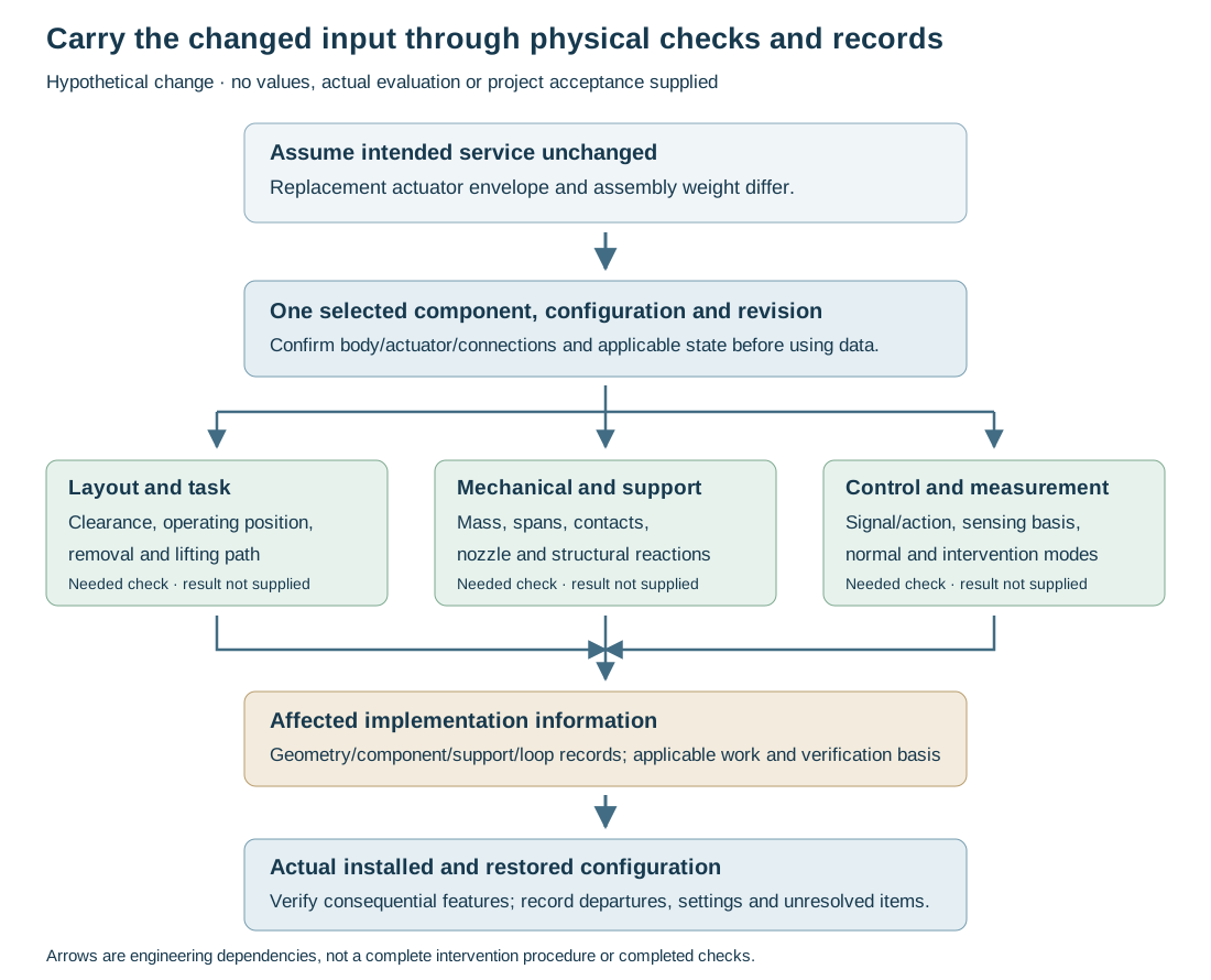
*Figure 22.1. The assumed change in actuator envelope and assembly weight enters several evaluations and implementation records. The same selected identity/state must connect those outputs to actual installed verification. Arrows identify consequences and information dependencies, not a complete work procedure or an accepted plant modification. [Structured record chain](assets/C21/replacement-record-chain.json).*
## As-built information is evidence of the resulting configuration
An as-built record preserves the installed arrangement needed for operation, inspection, maintenance and future change. Its value lies in the information it establishes. Routing, material, component and attachment details can matter to a later physical assessment. A stamp saying as-built without those relevant details cannot answer the engineering question.
A riser documentation example specifies the resulting routing, material/wall/coating, fittings and clamp details because operators need them for inspection and maintenance. That specific physical scope illustrates the broader purpose. Plant piping, buried systems and offshore/riser installations have different relevant conditions. The [buried, pipeline and offshore boundaries](#chapter-c11) should remain visible in the record. One drawing set should not be forced onto every case.
Record verification separately from the intended arrangement. A measured or observed field location, an inspection result, a test record and a restored operating configuration establish different facts. Identify their boundary, state and method. A pressure test does not prove that every instrument connection was restored, that a guide is free to slide or that a withdrawal path is usable.
Temporary arrangements need their own closure. Test blinds, spools, supports, locks, bypasses and isolated sensing paths can change the state. Document their selected removal or retention and the verified final condition. A spring setting called cold is meaningful only with its reference contents and equipment condition. [Support states](#chapter-c10) and [restoration](#chapter-c18) explain why the same coordinate or mark can mean different things before and after filling or testing.